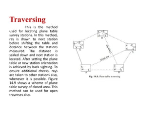
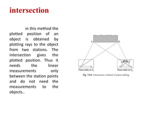
‘Basics of plane table surveying’
                by
    A. Ananthapadmanabha
            Asst. Prof.
Department of civil Engineering
              KSSEM
         BANGALORE-62
Plane Table Surveying
       Plane table is a graphical method of surveying in

which the field works and the plotting is done

simultaneously. It is particularly adopting in small

mapping. Plane table surveying is used for locating the

field computation of area of field
Merits of plane tabling

 It is most suitable for preparing small scale map or surveying

   small area.

 Field book is not necessary.

 It is particularly suitable for magnetic area where prismatic

   compass is not reliable.

 It is less costly.
Demerits of plane tabling
 Plane Table Essentially a tropical
  instruments.
 It is not suitable to work in wet
  climate.
 There are several accessories to be
  carried out and therefore they are
  likely to be lost.
Parts of plane Table:


 Plane      table   essentially   consist   of

  Drawing board mounted on tripod.


 Alidade.
Drawing board mounted on tripod
     A sheet of drawing paper, called plane table sheet
 is fastened to the board. Board is made up of well
 seasoned wood such as teak of size 40x30 to
 75x60cm. it had plane and smooth top. It is mounted
 on a tripod in manner that it can be leveled. Leveling
 up of the table is done by shifting the legs of tripod.
 Some tripod provided with leveling screw or by ball
 and socket head for accurate leveling.
Alidade
             Alidade consists of two

vertical sight vane fitted at end the end

of straightedge. The straight edge ruler

usually made of brass or teak wood

graduated beloved edge. One of the

sight veins is provided with narrow slit

and the other with a central vertical

wire or hair. Beveled working edge

alidade is called fiducial edge.
Telescopic
Alidade
It consists of a telescope
mounted on a column fixed to
the ruler The line of sight
through the telescope is kept
parallel to the beveled edge
of the ruler. The telescope
is provided with a level tube
and vertical graduation arc. If
horizontal sight is required
bubble in the level tube is
kept at the center. If inclined
sights are required vertical
graduation helps in noting the
inclination of the line of sight.
By providing telescope the
range and the accuracy of line
of sight is increased.
Plumbing Fork and
Plumb Bob
           Figure    shows     a     typical
plumbing fork with a plum bob. Plumbing
fork is a U-shaped metal frame with a
upper horizontal arm and a lower inclined
arm. The upper arm is provided with a
pointer at the end while the lower arm is
provided with a hook to suspend plumb
bob. When the plumbing fork is kept on
the plane table the vertical line (line of
plumb bob) passes through the pointed
edge of upper arm. The plumb bob helps
in transferring the ground point to the
drawing sheet and vice versa also.
Spirit Level
        A flat based spirit
level is used to level the
plane      table    during
surveying .To get perfect
level, spirit level should
show central position for
bubble       tube    when
checked        with     its
positions in any two
mutually perpendicular
direction.
Trough
compass
 •          It consists of a 80 to 150 mm long and 30

     mm wide box carrying a freely suspended needle

     at its center At the ends of the needle graduations

     are marked on the box to indicate zero to

     five degrees on either side of the centre. The box is

     provided with glass top to prevent oscillation of

     the needle by wind. When needle is centered

     (reading 0–0), the line of needle is parallel to the

     edge of the box. Hence marking on the edges in

     this state indicates magnetic north–south direction
Drawing Sheet and Accessories for
            Drawing
         A good quality, seasoned drawing sheet should be used for
plane table surveying. The drawing sheet may be rolled when not in
use, but should never is folded. For important works fibre glass sheets
or   paper   backed     with   thin     aluminium    sheets   are   used.
Clips clamps, adhesive tapes may be used for fixing drawing sheet to
the plane table. Sharp hard pencil, good quality eraser, pencil cutter and
sand paper to keep pencil point sharp are other accessories required for
the drawing work. If necessary, plastic sheet should be carried to cover
the drawing sheet from rain and dust.
1. Radiation:
          In this position
the point is located on
plane by drawing a ray
from the plane table
station to the point, and
plotting scale along the ray
the distance is measured
from the station to the
point. The method is
suitable for the survey of
the small areas which can
be commanded from a
single station.
Radiation
            After setting the plane
table on a station, say O, it is
required to find the plotted
position of various objects A, B, C,
D ….. . To get these positions, the
rays OA, OB, OC ….. are drawn
with soft pencil Then the
distances OA, OB, OC ….., are
measured scaled down and the
positions of A, B, C ….., are found
on the drawing sheets.
This method is suitable for
surveying small areas and is
convenient if the distances to be
measured are small. For larger
areas this method has wider
scope, if telescopic alidade is
used, in which the distances are
measured techno metrically
Intersection
         In this method the
plotted position of an
object is obtained by
plotting rays to the object
from two stations. The
intersection gives the
plotted position. Thus it
needs        the      linear
measurements            only
between the station points
and do not need the
measurements to the
objects. Figure 14.8 shows
the method for locating
objects A and B from plane
table
Traversing
           This is the method
used for locating plane table
survey stations. In this method,
ray is drawn to next station
before shifting the table and
distance between the stations
measured. The distance is
scaled down and next station is
located. After setting the plane
table at new station orientation
is achieved by back sighting. To
ensure additional checks, rays
are taken to other stations also,
whenever it is possible. Figure
14.9 shows a scheme of plane
table survey of closed area. This
method can be used for open
traverses also.
intersection

          in this method the
plotted position of an
object is obtained by
plotting rays to the object
from two stations. The
intersection gives the
plotted position. Thus it
needs         the      linear
measurements             only
between the station points
and do not need the
measurements to the
objects..
Errors in plane table surveying
Instrumental Errors
 The surface of plane table not perfectly plane.
 Beveled edge of alidade not straight.
 Sight vanes of alidade not perfectly perpendicular to the base
 Plane table clamp being loose.
 Magnetic compass being sluggish.
 Drawing sheet being of poor quality.


ttt
Personal Errors
•   Centering errors Leveling errors


• Orientation errors

• Sighting errors


• Errors in measurement


• Plotting errors


• 7. Errors due to instability of tripod

Plane table presentation 1

  • 1.
    ‘Basics of planetable surveying’ by A. Ananthapadmanabha Asst. Prof. Department of civil Engineering KSSEM BANGALORE-62
  • 3.
    Plane Table Surveying Plane table is a graphical method of surveying in which the field works and the plotting is done simultaneously. It is particularly adopting in small mapping. Plane table surveying is used for locating the field computation of area of field
  • 4.
    Merits of planetabling  It is most suitable for preparing small scale map or surveying small area.  Field book is not necessary.  It is particularly suitable for magnetic area where prismatic compass is not reliable.  It is less costly.
  • 5.
    Demerits of planetabling  Plane Table Essentially a tropical instruments.  It is not suitable to work in wet climate.  There are several accessories to be carried out and therefore they are likely to be lost.
  • 6.
    Parts of planeTable:  Plane table essentially consist of Drawing board mounted on tripod.  Alidade.
  • 7.
    Drawing board mountedon tripod A sheet of drawing paper, called plane table sheet is fastened to the board. Board is made up of well seasoned wood such as teak of size 40x30 to 75x60cm. it had plane and smooth top. It is mounted on a tripod in manner that it can be leveled. Leveling up of the table is done by shifting the legs of tripod. Some tripod provided with leveling screw or by ball and socket head for accurate leveling.
  • 8.
    Alidade Alidade consists of two vertical sight vane fitted at end the end of straightedge. The straight edge ruler usually made of brass or teak wood graduated beloved edge. One of the sight veins is provided with narrow slit and the other with a central vertical wire or hair. Beveled working edge alidade is called fiducial edge.
  • 9.
    Telescopic Alidade It consists ofa telescope mounted on a column fixed to the ruler The line of sight through the telescope is kept parallel to the beveled edge of the ruler. The telescope is provided with a level tube and vertical graduation arc. If horizontal sight is required bubble in the level tube is kept at the center. If inclined sights are required vertical graduation helps in noting the inclination of the line of sight. By providing telescope the range and the accuracy of line of sight is increased.
  • 10.
    Plumbing Fork and PlumbBob Figure shows a typical plumbing fork with a plum bob. Plumbing fork is a U-shaped metal frame with a upper horizontal arm and a lower inclined arm. The upper arm is provided with a pointer at the end while the lower arm is provided with a hook to suspend plumb bob. When the plumbing fork is kept on the plane table the vertical line (line of plumb bob) passes through the pointed edge of upper arm. The plumb bob helps in transferring the ground point to the drawing sheet and vice versa also.
  • 11.
    Spirit Level A flat based spirit level is used to level the plane table during surveying .To get perfect level, spirit level should show central position for bubble tube when checked with its positions in any two mutually perpendicular direction.
  • 12.
    Trough compass • It consists of a 80 to 150 mm long and 30 mm wide box carrying a freely suspended needle at its center At the ends of the needle graduations are marked on the box to indicate zero to five degrees on either side of the centre. The box is provided with glass top to prevent oscillation of the needle by wind. When needle is centered (reading 0–0), the line of needle is parallel to the edge of the box. Hence marking on the edges in this state indicates magnetic north–south direction
  • 13.
    Drawing Sheet andAccessories for Drawing A good quality, seasoned drawing sheet should be used for plane table surveying. The drawing sheet may be rolled when not in use, but should never is folded. For important works fibre glass sheets or paper backed with thin aluminium sheets are used. Clips clamps, adhesive tapes may be used for fixing drawing sheet to the plane table. Sharp hard pencil, good quality eraser, pencil cutter and sand paper to keep pencil point sharp are other accessories required for the drawing work. If necessary, plastic sheet should be carried to cover the drawing sheet from rain and dust.
  • 14.
    1. Radiation: In this position the point is located on plane by drawing a ray from the plane table station to the point, and plotting scale along the ray the distance is measured from the station to the point. The method is suitable for the survey of the small areas which can be commanded from a single station.
  • 15.
    Radiation After setting the plane table on a station, say O, it is required to find the plotted position of various objects A, B, C, D ….. . To get these positions, the rays OA, OB, OC ….. are drawn with soft pencil Then the distances OA, OB, OC ….., are measured scaled down and the positions of A, B, C ….., are found on the drawing sheets. This method is suitable for surveying small areas and is convenient if the distances to be measured are small. For larger areas this method has wider scope, if telescopic alidade is used, in which the distances are measured techno metrically
  • 16.
    Intersection In this method the plotted position of an object is obtained by plotting rays to the object from two stations. The intersection gives the plotted position. Thus it needs the linear measurements only between the station points and do not need the measurements to the objects. Figure 14.8 shows the method for locating objects A and B from plane table
  • 17.
    Traversing This is the method used for locating plane table survey stations. In this method, ray is drawn to next station before shifting the table and distance between the stations measured. The distance is scaled down and next station is located. After setting the plane table at new station orientation is achieved by back sighting. To ensure additional checks, rays are taken to other stations also, whenever it is possible. Figure 14.9 shows a scheme of plane table survey of closed area. This method can be used for open traverses also.
  • 18.
    intersection in this method the plotted position of an object is obtained by plotting rays to the object from two stations. The intersection gives the plotted position. Thus it needs the linear measurements only between the station points and do not need the measurements to the objects..
  • 19.
    Errors in planetable surveying Instrumental Errors  The surface of plane table not perfectly plane.  Beveled edge of alidade not straight.  Sight vanes of alidade not perfectly perpendicular to the base  Plane table clamp being loose.  Magnetic compass being sluggish.  Drawing sheet being of poor quality. ttt
  • 20.
    Personal Errors • Centering errors Leveling errors • Orientation errors • Sighting errors • Errors in measurement • Plotting errors • 7. Errors due to instability of tripod