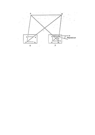
SlideShare a Scribd company logo
Y.B. PATIL POLYTECHNIC
SECTOR NO. 29, AKURDI, PUNE -411044, INDIA
HRISHIKESH TARANGE – Y-2070-1901340102
ATHARVA PATIL – Y-2075-1901340081
YOGESH YELAVI -Y-2083-1901340103
PRATHAMESH ROKDE – Y-2031-1901340079
AVINASH SAKHERE – Y-2058 -1901340080
DAVENDRA SUTHAR – Y-2077-1901340104
This is to certify ;has satisfactorily carried out and completed the project work entitled
methods of plane table surveying
This work is being submitted for the award of Diploma in civil Engineering partial fulfillment of
prescribed syllabus of M.S.B.T.E Mumbai for academic Year 2020
MR.AMIT GHONGADE MR,ABHIJEET PATIL
GUIDE HOD CIVIL DEPARTMENT
PRINCIPLE
PROF.A.S KONDEKAR
Micro project proposal
Topic-methods of plane table surveying
1.Aims/benefits of micro project: To get knowledge about methods of plane table
surveying its objective its component use in civil engineering introduction & knowledge of
methods of plane table surveying
2 Course outcome addressed.
1 To learn about methods of plane table surveying
2. To learn about component & it use
3. To learn about their advantage & disadvantage
3 Action plan
Sr.
No.
Details of activity Planned
Start date
Planed
Finished
date
Name of
responsible
team member
1) Collection of information. 20/06/2020 20/06/2020 HRISHIKESH
TARANGE –
Y1171
ATHARVA
PATIL – Y1154
2) Working of Microsoft
Word.
20/06/2020 23/06/2020 YOGESH
YELAVI –
Y1177
PRATHAMESH
ROKDE –
Y1161
3) Taking Prints of the project
made in Microsoft Word &
Microsoft word & binding it
22/06/2020 22/06/2020 AVINASH
SAKHERE –
Y1162
DAVENDRA
SUTAR –
Y1170
5 Resource Required
Sr.no Name of resource /materials specification Qty Remark
1 Internet and reference book Collect
information
1
2 laptop Working on
Microsoft word
1
Name of team member with roll no
HRISHIKESH TARANGE – Y2070
ATHARVA PATIL – Y2075
YOGESH YELAVI – Y2083
PRATHAMESH ROKDE – Y2031
AVINASH SAKHERE – Y2058
DAVENDRA SUTAR – Y2077
Micro project evaluation sheet
Name of student
HRISHIKESH TARANGE – Y2070
ATHARVA PATIL – Y2075
YOGESH YELAVI – Y2083
PRATHAMESH ROKDE – Y2031
AVINASH SAKHERE – Y2058
DAVENDRA SUTAR – Y2077
Name of programme: micro project on the methods of plane table surveying
Semester:1st
Course title: Advance surveying
Title of micro project :methods of plane table surveying
Course outcome achieved
1 To learn about methods of plane table surveying
2. To learn about component & it use
3. To learn about their advantage & disadvantage
Sr
no
Characteristic to be
assessed
Poor
(mark 1-3)
Average
(mark 4-5)
Good
(mark 6-8)
Excellent
(mark 9-10)
Sub total
(A)PROCESS AND PRODUCT ASSESSMENT CONVERT ABOVE TOTAL MARK OUT OF 6 MARK
1 Relevance to the course
2 Literature review/information
3 Completion of the target as
per project proposal
4 Analysis of date and
representation
5 Quality of prototype/model
6 Report preparation
(B)INDIVIDUAL PRESENTATION/VIVA CONVERT ABOVE MARK OUT OF 4 MARKS
7 Presentation
8 viva
NAME ROLL NO
(A)
PROCESS AND
PRODUCT
(B)
INDIVIDUAL
PRESENTATIO
TOTAL
MARK (10
MARK)
ASSESSMENT
(6MARK)
N/ VIVA (4
MARK)
HRISHIKESH
TARANGE
Y-1171
ATHARVA PATIL Y-1154
YOGESH YELAVI Y-1177
PRATHAMESH
ROKDE
Y-1161
AVINASH SAKHERE Y-1162
DAVENDRA SUTAR Y-1170
COMMENTS/SUGGESTION ABOUT TEAMWORK/LEADERSHIP/INTERPERSONAL
COMMUNICATION ( IF ANY)
NAME AND DESIGNATION OF TEACHER …………………………………………………
DATED SIGNATURE………………………………
What is Plane Table Surveying?
Plane table surveying is the fastest method of surveying. In this type of surveying plotting of
the plan and field observations can be done simultaneously. In case of plane table surveying
Geometrical conditions of site are manuscript in the map sheet using plane table and alidade
after that topographic details are arranged on the map.
Equipment Used in Plane Table Survey
General equipment used for conducting plane table survey are
● Plane table
● Alidade for sighting (telescopic or simple)
● Plumb bob and plumb fork
● Compass
● Spirit level
● Chain
● Ranging rods
● Tripod
● Drawing sheet and drawing tools
● Paper clips or screwsIn a plane table surveying a table top, similar to a drawing
board fitted onto a tripod is the main instrument. A drawing sheet is fixed on to the
table top, the observations are made to the objects, distances are scaled down and
the objects are plotted in the field itself.
Since the plotting is made in the field itself, there is no chance of omitting any necessary
measurement in this surveying. However the accuracy achieved in this type of surveying is
less. Hence this type of surveying is used for filling up details between the survey stations
previously fixed by other methods.
The most commonly used plane table is shown in Fig. 1. It consists of a well seasoned
wooden table top mounted on a tripod. The table top can rotate about the vertical axis freely.
Whenever necessary the table can be clamped in the desired orientation. The table can be
levelled by adjusting tripod legs.
Fig: Plane table with tripod stand
Equipments for Plane Table Surveying
The following accessories are required to carry out plane table survey:
1. Alidade
2. Plumbing fork with plumb bob
3. Spirit level
4. Trough compass
5. Drawing sheets and accessories for drawing.
1. Alidade
It is a straight edge ruler having some form of sighting device. One edge of the ruler is
bevelled and is graduated. Always this edge is used for drawing line of sight. Depending on
the type of line of sight there are two types of alidade:
(a) Plain alidade
(b) Telescopic alidade
Plain Alidade:
Figure 2 shows a typical plain alidade. A sight vane is provided at each end of the ruler. The
vane with narrow slit serves as eye vane and the other with wide slit and having a thin wire
at its centre serves as object vane.
The two vanes are provided with hinges at the ends of the ruler so that when not in use they
can be folded on the ruler. Plain alidade is not suitable in surveying hilly areas as the
inclination of line of sight in this case is limited.
Fig: 2 – Plane Alidade
Telescopic Alidade:
It consists of a telescope mounted on a column fixed to the ruler [Fig. 3]. The line of sight
through the telescope is kept parallel to the bevelled edge of the ruler. The telescope is
provided with a level tube and vertical graduation arc. If horizontal sight is required bubbles
in the level tube are kept at the centre.
If inclined sights are required vertical graduation helps in noting the inclination of the line of
sight. By providing a telescope the range and the accuracy of line of sight is increased.
Fig. 3: Telescopic alidade
2. Plumbing Fork and Plumb Bob
Figure 4 shows a typical plumbing fork with a plum bob. Plumbing fork is a U-shaped metal
frame with an upper horizontal arm and a lower inclined arm. The upper arm is provided with
a pointer at the end while the lower arm is provided with a hook to suspend plumb bob.
When the plumbing fork is kept on the plane table the vertical line (line of plumb bob) passes
through the pointed edge of the upper arm. The plumb bob helps in transferring the ground
point to the drawing sheet and vice versa also.
Fig. 4: Plumbing fork and plumb bob
3. Spirit Level
A flat based spirit level is used to level the plane table during surveying (Fig.5). To get
perfect level, spirit level should show the central position for bubble tube when checked with
its positions in any two mutually perpendicular directions.
Fig. 5: Spirit level
4. Trough Compass
It consists of a 80 to 150 mm long and 30 mm wide box carrying a freely suspended needle
at its centre (Ref. Fig. 6). At the ends of the needle graduations are marked on the box to
indicate zero to five degrees on either side of the centre. The box is provided with a glass
top to prevent oscillation of the needle by wind.
When the needle is centred (reading 0–0), the line of needle is parallel to the edge of the
box. Hence marking on the edges in this state indicates magnetic north–south direction.
Fig. 6: Trough compass
5. Drawing Sheet and Accessories for Drawing
A good quality, seasoned drawing sheet should be used for plane table surveying. The
drawing sheet may be rolled when not in use, but should never be folded. For important
works fibre glass sheets or paper backed with thin aluminium sheets are used.
Clips clamps, adhesive tapes may be used for fixing drawing sheets to the plane table.
Sharp hard pencil, good quality eraser, pencil cutter and sandpaper to keep pencil point
sharp are other accessories required for the drawing work. If necessary, a plastic sheet
should be carried to cover the drawing sheet from rain and dust.
Plane table survey equipment is arranged in 4 steps as follows
Fixing of Plane Table
Fix the plane table to the tripod stand. Arrange the drawing sheet on the plane table using
paper clips or thumb screws. The sheet should be in one position from first to last.
Leveling of Plane Table
Plane table should be leveled using spirit level. For small works, eye estimation can be ok.
Centering of Plane Table
The table should be centered by using a plumbing fork. By which we can arrange the plotted
point exactly over the ground point.
Orientation of Plane Table
Whenever we are using more than one instrument station, orientation is essential. It can be
done by using compass or back sighting. In this case, the plane table is rotated such that
plotted lines in the drawing sheet are parallel to corresponding lines on the ground.
Methods of Plane Table Surveying
Generally there are four methods available to perform plane table surveying. They are
1. Radiation
2. Intersection
3. Traversing
4. Resection
Radiation
In this method, the plane table is located at one point “o” as shown in fig. and performs the
whole from that point. From point O, sight the points A,B,C,D and E using alidade, locate
and plot the points as a,b,c,d and e in the drawing sheet.
Intersection
In this method we can locate the point by plotting two rays from two known stations. As
shown in figure, P and Q are the known stations. First the equipment is placed on P and plot
the lines by sighting the stations A, B and Q. Then shift the equipment to station Q and plot
the lines by sighting stations A, B and P. Finally, the intersection of A and B rays is the
required location of the point of intersection.
Traversing
Traversing is the connection of a series of straight lines. In case of traversing, the plane
table is located at one point for suppose A as shown below. From that point sight towards B
and measure the distance AB. Then shift the plane table to point B and sight towards A and
measure BA. Average distances of AB and Ba are plotted to scale in the drawing sheet.
Then Sight the point C from B and measure BC and repeat the same procedure until the last
point. Conduct some checks at some points. Finally traverse lines are plotted on the drawing
sheet.
Resection
Resection is a method of plane table surveying in which the location of the plane table is
unknown and it is determined by sighting it to known points or plotted points. It is also called
a method of orientation and it can be conducted by two field conditions as follows.
● The three-point problem
● The two-point problem
The Three Point Problem
In this condition, three points and their positions in the field are known. Plane table is placed
at an apposition from where all the three points are visible. So, by sighting those three points
we can locate the point where equipment is located. This can be achieved by many methods
as follows.
● Tracing method
● Lehmann method
● Analytical methods
● Graphical method
Tracing Method in Plane Table Surveying
In tracing method, the plane table is located at a point from where three points are visible.
The table is oriented with respect to the plotted lines of those three points. Place the tracing
paper on the drawing sheet and again sight the three points and plot the radiating lines. The
tracing paper is then moved above the drawing sheet until the three radiating lines pass
through corresponding points previously plotted on the map. Finally, the position of the plane
table is marked.
Lehmann Method
In this method, the Plane table is located at a point P and sights the station A, B and C and
plot the rays Aa, Bb, and Cc. The rays form a small triangle which is called a triangle of
error. Another point P1 is chosen to reduce the error and sight the point A from P1 similarly
to B and C. Which will give another triangle of error. Repeat this procedure until error
becomes zero.
Analytical Methods
There are many analytical methods developed in three-point problem conditions. In this
method, from station P A, B and C are sighted and note the values of angles and lengths.
From these values determine the position of unknown points by using analytical formulae.
Graphical Method
In graphical method also, angles and lengths are determined and represented on a graph
and determines the location of the plane table.
The Two-Point Problem
In the two-point problem, two points are sighted from another point corresponding to the
points given in the plane table sheet. Here two cases are to be discussed.
Case 1: when the points can be occupied by the plane table
As shown in fig. A and B are the two points corresponding to the points a and b. Now, the
plane table is located at B and oriented by sighting A. Sight C from B and bx is plotted on the
sheet. Then shift the plane table to C, oriented by backsighting B along xb. Then alidade is
placed over a and sight station A, then line Aa cuts the line bx at somewhere which is
located as point c at station C.
Case2: When the plane table cannot occupy the controlling stations
In this case, an auxiliary point D is considered nearer to C. Locate the plane table at D
according to the line ab parallel to AB. Then sight the station A and B corresponding to a and
b. the rays drawn are intersected at some point which is marked as d. Then sight towards C
by placing a alidade at d. mark the distance Dc as c1. Shift the table to C and backsight to D
with reference to c1.
Then sight A corresponding to a, the ray drawn, intersects the previously drawn ray from D
in c2. From c2 sight B draws a ray which intersects db and marks the intersection as b1. The
table is oriented till ab comes in line with P. From P sight and draw rays Aa and Ba. The
intersection of these two rays will give the Location of Point C.
ASU MP.docx

More Related Content

Similar to ASU MP.docx

Plane Table Surveying PPt
Plane Table Surveying PPtPlane Table Surveying PPt
Plane Table Surveying PPt
mohit kumar panchal
 
Detailed analysis of plane table surveying
Detailed analysis of plane table surveyingDetailed analysis of plane table surveying
Detailed analysis of plane table surveyingsumitvikram
 
plane Table surveing.pptx
plane Table surveing.pptxplane Table surveing.pptx
plane Table surveing.pptx
raziaramzan1
 
PLANE TABLE SURVEYING
PLANE TABLE SURVEYINGPLANE TABLE SURVEYING
PLANE TABLE SURVEYING
PiyushKumar621
 
unit-5-plane-table-survey-orientation-radiation-intersection-traversing-resec...
unit-5-plane-table-survey-orientation-radiation-intersection-traversing-resec...unit-5-plane-table-survey-orientation-radiation-intersection-traversing-resec...
unit-5-plane-table-survey-orientation-radiation-intersection-traversing-resec...
sharmajivijay99
 
unit-5-plane-table-survey-orientation-radiation-intersection-traversing-resec...
unit-5-plane-table-survey-orientation-radiation-intersection-traversing-resec...unit-5-plane-table-survey-orientation-radiation-intersection-traversing-resec...
unit-5-plane-table-survey-orientation-radiation-intersection-traversing-resec...
sharmajivijay99
 
Plane table surveying
Plane table surveying Plane table surveying
Plane table surveying
PratikShinde113
 
chapter 4angle.pdf
chapter 4angle.pdfchapter 4angle.pdf
chapter 4angle.pdf
sandipanpaul16
 
Plane Table Survey
Plane Table SurveyPlane Table Survey
Plane Table Survey
Bhavik A Shah
 
Mass diagram and its characeristics .ppt
Mass diagram and its characeristics .pptMass diagram and its characeristics .ppt
Mass diagram and its characeristics .ppt
NITINSURESH30
 
Plane table surveying
Plane table surveyingPlane table surveying
Plane table surveying
NikMankar26
 
Traversing
TraversingTraversing
Traversing
Arissa Loh
 
Surveying Lab II Manual
Surveying Lab II ManualSurveying Lab II Manual
Surveying Lab II Manual
Malla Reddy University
 
planetablesurvey-131027094131-phpapp01.pdf
planetablesurvey-131027094131-phpapp01.pdfplanetablesurvey-131027094131-phpapp01.pdf
planetablesurvey-131027094131-phpapp01.pdf
ssuser23e4af
 
planetablesurvey-131027094131-phpapp01 (1).pdf
planetablesurvey-131027094131-phpapp01 (1).pdfplanetablesurvey-131027094131-phpapp01 (1).pdf
planetablesurvey-131027094131-phpapp01 (1).pdf
PotterheadKevin
 
planetablesurvey-131027094131-phpapp01.pdf
planetablesurvey-131027094131-phpapp01.pdfplanetablesurvey-131027094131-phpapp01.pdf
planetablesurvey-131027094131-phpapp01.pdf
RinsaFebin
 
Plane Table Survey
Plane Table SurveyPlane Table Survey
Plane Table Survey
GAURAV. H .TANDON
 
Surveying_Plane Table Practical.ppt
Surveying_Plane Table Practical.pptSurveying_Plane Table Practical.ppt
Surveying_Plane Table Practical.ppt
HasibMehdi
 
Site Surveying Traversing
Site Surveying TraversingSite Surveying Traversing
Site Surveying Traversing
ashleyyeap
 
Sem 2 Site surveying report 2
Sem 2 Site surveying report 2Sem 2 Site surveying report 2
Sem 2 Site surveying report 2
Est
 

Similar to ASU MP.docx (20)

Plane Table Surveying PPt
Plane Table Surveying PPtPlane Table Surveying PPt
Plane Table Surveying PPt
 
Detailed analysis of plane table surveying
Detailed analysis of plane table surveyingDetailed analysis of plane table surveying
Detailed analysis of plane table surveying
 
plane Table surveing.pptx
plane Table surveing.pptxplane Table surveing.pptx
plane Table surveing.pptx
 
PLANE TABLE SURVEYING
PLANE TABLE SURVEYINGPLANE TABLE SURVEYING
PLANE TABLE SURVEYING
 
unit-5-plane-table-survey-orientation-radiation-intersection-traversing-resec...
unit-5-plane-table-survey-orientation-radiation-intersection-traversing-resec...unit-5-plane-table-survey-orientation-radiation-intersection-traversing-resec...
unit-5-plane-table-survey-orientation-radiation-intersection-traversing-resec...
 
unit-5-plane-table-survey-orientation-radiation-intersection-traversing-resec...
unit-5-plane-table-survey-orientation-radiation-intersection-traversing-resec...unit-5-plane-table-survey-orientation-radiation-intersection-traversing-resec...
unit-5-plane-table-survey-orientation-radiation-intersection-traversing-resec...
 
Plane table surveying
Plane table surveying Plane table surveying
Plane table surveying
 
chapter 4angle.pdf
chapter 4angle.pdfchapter 4angle.pdf
chapter 4angle.pdf
 
Plane Table Survey
Plane Table SurveyPlane Table Survey
Plane Table Survey
 
Mass diagram and its characeristics .ppt
Mass diagram and its characeristics .pptMass diagram and its characeristics .ppt
Mass diagram and its characeristics .ppt
 
Plane table surveying
Plane table surveyingPlane table surveying
Plane table surveying
 
Traversing
TraversingTraversing
Traversing
 
Surveying Lab II Manual
Surveying Lab II ManualSurveying Lab II Manual
Surveying Lab II Manual
 
planetablesurvey-131027094131-phpapp01.pdf
planetablesurvey-131027094131-phpapp01.pdfplanetablesurvey-131027094131-phpapp01.pdf
planetablesurvey-131027094131-phpapp01.pdf
 
planetablesurvey-131027094131-phpapp01 (1).pdf
planetablesurvey-131027094131-phpapp01 (1).pdfplanetablesurvey-131027094131-phpapp01 (1).pdf
planetablesurvey-131027094131-phpapp01 (1).pdf
 
planetablesurvey-131027094131-phpapp01.pdf
planetablesurvey-131027094131-phpapp01.pdfplanetablesurvey-131027094131-phpapp01.pdf
planetablesurvey-131027094131-phpapp01.pdf
 
Plane Table Survey
Plane Table SurveyPlane Table Survey
Plane Table Survey
 
Surveying_Plane Table Practical.ppt
Surveying_Plane Table Practical.pptSurveying_Plane Table Practical.ppt
Surveying_Plane Table Practical.ppt
 
Site Surveying Traversing
Site Surveying TraversingSite Surveying Traversing
Site Surveying Traversing
 
Sem 2 Site surveying report 2
Sem 2 Site surveying report 2Sem 2 Site surveying report 2
Sem 2 Site surveying report 2
 

More from NAUGHTYBOY9

MECHANICS OF STRUCTURE.pdf
MECHANICS OF STRUCTURE.pdfMECHANICS OF STRUCTURE.pdf
MECHANICS OF STRUCTURE.pdf
NAUGHTYBOY9
 
BUILDINGTECHNOLOGY AND PLANNING.pdf
BUILDINGTECHNOLOGY AND PLANNING.pdfBUILDINGTECHNOLOGY AND PLANNING.pdf
BUILDINGTECHNOLOGY AND PLANNING.pdf
NAUGHTYBOY9
 
ENGINEERING GEOLOGY.pdf
ENGINEERING GEOLOGY.pdfENGINEERING GEOLOGY.pdf
ENGINEERING GEOLOGY.pdf
NAUGHTYBOY9
 
Fluid mechanics unit 3.pdf
Fluid mechanics unit 3.pdfFluid mechanics unit 3.pdf
Fluid mechanics unit 3.pdf
NAUGHTYBOY9
 
Engineering mathematics 3.pdf
Engineering mathematics 3.pdfEngineering mathematics 3.pdf
Engineering mathematics 3.pdf
NAUGHTYBOY9
 
FLUID MECHANICS.pdf
FLUID MECHANICS.pdfFLUID MECHANICS.pdf
FLUID MECHANICS.pdf
NAUGHTYBOY9
 
MECHANICS OF STRUCTURE.pdf
MECHANICS OF STRUCTURE.pdfMECHANICS OF STRUCTURE.pdf
MECHANICS OF STRUCTURE.pdf
NAUGHTYBOY9
 
BUILDING TECHNOLOGY AND ARCHITECTURAL PLANNING.pdf
BUILDING TECHNOLOGY AND ARCHITECTURAL PLANNING.pdfBUILDING TECHNOLOGY AND ARCHITECTURAL PLANNING.pdf
BUILDING TECHNOLOGY AND ARCHITECTURAL PLANNING.pdf
NAUGHTYBOY9
 
GTE_micro_project.docx
GTE_micro_project.docxGTE_micro_project.docx
GTE_micro_project.docx
NAUGHTYBOY9
 
HYD MP.docx
HYD MP.docxHYD MP.docx
HYD MP.docx
NAUGHTYBOY9
 
RBE MP.docx
RBE MP.docxRBE MP.docx
RBE MP.docx
NAUGHTYBOY9
 
TOS MP.docx
TOS MP.docxTOS MP.docx
TOS MP.docx
NAUGHTYBOY9
 
EST MP.docx
EST MP.docxEST MP.docx
EST MP.docx
NAUGHTYBOY9
 
GTE MP.docx
GTE MP.docxGTE MP.docx
GTE MP.docx
NAUGHTYBOY9
 
BPD MP.docx
BPD MP.docxBPD MP.docx
BPD MP.docx
NAUGHTYBOY9
 
TYPES OF SUPPORTS,BEAM AND LOADING.docx
TYPES OF SUPPORTS,BEAM AND LOADING.docxTYPES OF SUPPORTS,BEAM AND LOADING.docx
TYPES OF SUPPORTS,BEAM AND LOADING.docx
NAUGHTYBOY9
 
TRAFFIC CONTROL DEVICES AND ROAD SIGNS.docx
TRAFFIC CONTROL DEVICES AND ROAD SIGNS.docxTRAFFIC CONTROL DEVICES AND ROAD SIGNS.docx
TRAFFIC CONTROL DEVICES AND ROAD SIGNS.docx
NAUGHTYBOY9
 
BCO MP.docx
BCO MP.docxBCO MP.docx
BCO MP.docx
NAUGHTYBOY9
 
ADMIXTURE USED IN CONCRETE.docx
ADMIXTURE USED IN CONCRETE.docxADMIXTURE USED IN CONCRETE.docx
ADMIXTURE USED IN CONCRETE.docx
NAUGHTYBOY9
 
CME MP.docx
CME MP.docxCME MP.docx
CME MP.docx
NAUGHTYBOY9
 

More from NAUGHTYBOY9 (20)

MECHANICS OF STRUCTURE.pdf
MECHANICS OF STRUCTURE.pdfMECHANICS OF STRUCTURE.pdf
MECHANICS OF STRUCTURE.pdf
 
BUILDINGTECHNOLOGY AND PLANNING.pdf
BUILDINGTECHNOLOGY AND PLANNING.pdfBUILDINGTECHNOLOGY AND PLANNING.pdf
BUILDINGTECHNOLOGY AND PLANNING.pdf
 
ENGINEERING GEOLOGY.pdf
ENGINEERING GEOLOGY.pdfENGINEERING GEOLOGY.pdf
ENGINEERING GEOLOGY.pdf
 
Fluid mechanics unit 3.pdf
Fluid mechanics unit 3.pdfFluid mechanics unit 3.pdf
Fluid mechanics unit 3.pdf
 
Engineering mathematics 3.pdf
Engineering mathematics 3.pdfEngineering mathematics 3.pdf
Engineering mathematics 3.pdf
 
FLUID MECHANICS.pdf
FLUID MECHANICS.pdfFLUID MECHANICS.pdf
FLUID MECHANICS.pdf
 
MECHANICS OF STRUCTURE.pdf
MECHANICS OF STRUCTURE.pdfMECHANICS OF STRUCTURE.pdf
MECHANICS OF STRUCTURE.pdf
 
BUILDING TECHNOLOGY AND ARCHITECTURAL PLANNING.pdf
BUILDING TECHNOLOGY AND ARCHITECTURAL PLANNING.pdfBUILDING TECHNOLOGY AND ARCHITECTURAL PLANNING.pdf
BUILDING TECHNOLOGY AND ARCHITECTURAL PLANNING.pdf
 
GTE_micro_project.docx
GTE_micro_project.docxGTE_micro_project.docx
GTE_micro_project.docx
 
HYD MP.docx
HYD MP.docxHYD MP.docx
HYD MP.docx
 
RBE MP.docx
RBE MP.docxRBE MP.docx
RBE MP.docx
 
TOS MP.docx
TOS MP.docxTOS MP.docx
TOS MP.docx
 
EST MP.docx
EST MP.docxEST MP.docx
EST MP.docx
 
GTE MP.docx
GTE MP.docxGTE MP.docx
GTE MP.docx
 
BPD MP.docx
BPD MP.docxBPD MP.docx
BPD MP.docx
 
TYPES OF SUPPORTS,BEAM AND LOADING.docx
TYPES OF SUPPORTS,BEAM AND LOADING.docxTYPES OF SUPPORTS,BEAM AND LOADING.docx
TYPES OF SUPPORTS,BEAM AND LOADING.docx
 
TRAFFIC CONTROL DEVICES AND ROAD SIGNS.docx
TRAFFIC CONTROL DEVICES AND ROAD SIGNS.docxTRAFFIC CONTROL DEVICES AND ROAD SIGNS.docx
TRAFFIC CONTROL DEVICES AND ROAD SIGNS.docx
 
BCO MP.docx
BCO MP.docxBCO MP.docx
BCO MP.docx
 
ADMIXTURE USED IN CONCRETE.docx
ADMIXTURE USED IN CONCRETE.docxADMIXTURE USED IN CONCRETE.docx
ADMIXTURE USED IN CONCRETE.docx
 
CME MP.docx
CME MP.docxCME MP.docx
CME MP.docx
 

Recently uploaded

Water Industry Process Automation and Control Monthly - May 2024.pdf
Water Industry Process Automation and Control Monthly - May 2024.pdfWater Industry Process Automation and Control Monthly - May 2024.pdf
Water Industry Process Automation and Control Monthly - May 2024.pdf
Water Industry Process Automation & Control
 
CME397 Surface Engineering- Professional Elective
CME397 Surface Engineering- Professional ElectiveCME397 Surface Engineering- Professional Elective
CME397 Surface Engineering- Professional Elective
karthi keyan
 
WATER CRISIS and its solutions-pptx 1234
WATER CRISIS and its solutions-pptx 1234WATER CRISIS and its solutions-pptx 1234
WATER CRISIS and its solutions-pptx 1234
AafreenAbuthahir2
 
J.Yang, ICLR 2024, MLILAB, KAIST AI.pdf
J.Yang,  ICLR 2024, MLILAB, KAIST AI.pdfJ.Yang,  ICLR 2024, MLILAB, KAIST AI.pdf
J.Yang, ICLR 2024, MLILAB, KAIST AI.pdf
MLILAB
 
ethical hacking-mobile hacking methods.ppt
ethical hacking-mobile hacking methods.pptethical hacking-mobile hacking methods.ppt
ethical hacking-mobile hacking methods.ppt
Jayaprasanna4
 
Industrial Training at Shahjalal Fertilizer Company Limited (SFCL)
Industrial Training at Shahjalal Fertilizer Company Limited (SFCL)Industrial Training at Shahjalal Fertilizer Company Limited (SFCL)
Industrial Training at Shahjalal Fertilizer Company Limited (SFCL)
MdTanvirMahtab2
 
Gen AI Study Jams _ For the GDSC Leads in India.pdf
Gen AI Study Jams _ For the GDSC Leads in India.pdfGen AI Study Jams _ For the GDSC Leads in India.pdf
Gen AI Study Jams _ For the GDSC Leads in India.pdf
gdsczhcet
 
road safety engineering r s e unit 3.pdf
road safety engineering  r s e unit 3.pdfroad safety engineering  r s e unit 3.pdf
road safety engineering r s e unit 3.pdf
VENKATESHvenky89705
 
ASME IX(9) 2007 Full Version .pdf
ASME IX(9)  2007 Full Version       .pdfASME IX(9)  2007 Full Version       .pdf
ASME IX(9) 2007 Full Version .pdf
AhmedHussein950959
 
ethical hacking in wireless-hacking1.ppt
ethical hacking in wireless-hacking1.pptethical hacking in wireless-hacking1.ppt
ethical hacking in wireless-hacking1.ppt
Jayaprasanna4
 
Immunizing Image Classifiers Against Localized Adversary Attacks
Immunizing Image Classifiers Against Localized Adversary AttacksImmunizing Image Classifiers Against Localized Adversary Attacks
Immunizing Image Classifiers Against Localized Adversary Attacks
gerogepatton
 
block diagram and signal flow graph representation
block diagram and signal flow graph representationblock diagram and signal flow graph representation
block diagram and signal flow graph representation
Divya Somashekar
 
power quality voltage fluctuation UNIT - I.pptx
power quality voltage fluctuation UNIT - I.pptxpower quality voltage fluctuation UNIT - I.pptx
power quality voltage fluctuation UNIT - I.pptx
ViniHema
 
Planning Of Procurement o different goods and services
Planning Of Procurement o different goods and servicesPlanning Of Procurement o different goods and services
Planning Of Procurement o different goods and services
JoytuBarua2
 
一比一原版(SFU毕业证)西蒙菲莎大学毕业证成绩单如何办理
一比一原版(SFU毕业证)西蒙菲莎大学毕业证成绩单如何办理一比一原版(SFU毕业证)西蒙菲莎大学毕业证成绩单如何办理
一比一原版(SFU毕业证)西蒙菲莎大学毕业证成绩单如何办理
bakpo1
 
MCQ Soil mechanics questions (Soil shear strength).pdf
MCQ Soil mechanics questions (Soil shear strength).pdfMCQ Soil mechanics questions (Soil shear strength).pdf
MCQ Soil mechanics questions (Soil shear strength).pdf
Osamah Alsalih
 
NO1 Uk best vashikaran specialist in delhi vashikaran baba near me online vas...
NO1 Uk best vashikaran specialist in delhi vashikaran baba near me online vas...NO1 Uk best vashikaran specialist in delhi vashikaran baba near me online vas...
NO1 Uk best vashikaran specialist in delhi vashikaran baba near me online vas...
Amil Baba Dawood bangali
 
DESIGN A COTTON SEED SEPARATION MACHINE.docx
DESIGN A COTTON SEED SEPARATION MACHINE.docxDESIGN A COTTON SEED SEPARATION MACHINE.docx
DESIGN A COTTON SEED SEPARATION MACHINE.docx
FluxPrime1
 
H.Seo, ICLR 2024, MLILAB, KAIST AI.pdf
H.Seo,  ICLR 2024, MLILAB,  KAIST AI.pdfH.Seo,  ICLR 2024, MLILAB,  KAIST AI.pdf
H.Seo, ICLR 2024, MLILAB, KAIST AI.pdf
MLILAB
 
一比一原版(UofT毕业证)多伦多大学毕业证成绩单如何办理
一比一原版(UofT毕业证)多伦多大学毕业证成绩单如何办理一比一原版(UofT毕业证)多伦多大学毕业证成绩单如何办理
一比一原版(UofT毕业证)多伦多大学毕业证成绩单如何办理
ydteq
 

Recently uploaded (20)

Water Industry Process Automation and Control Monthly - May 2024.pdf
Water Industry Process Automation and Control Monthly - May 2024.pdfWater Industry Process Automation and Control Monthly - May 2024.pdf
Water Industry Process Automation and Control Monthly - May 2024.pdf
 
CME397 Surface Engineering- Professional Elective
CME397 Surface Engineering- Professional ElectiveCME397 Surface Engineering- Professional Elective
CME397 Surface Engineering- Professional Elective
 
WATER CRISIS and its solutions-pptx 1234
WATER CRISIS and its solutions-pptx 1234WATER CRISIS and its solutions-pptx 1234
WATER CRISIS and its solutions-pptx 1234
 
J.Yang, ICLR 2024, MLILAB, KAIST AI.pdf
J.Yang,  ICLR 2024, MLILAB, KAIST AI.pdfJ.Yang,  ICLR 2024, MLILAB, KAIST AI.pdf
J.Yang, ICLR 2024, MLILAB, KAIST AI.pdf
 
ethical hacking-mobile hacking methods.ppt
ethical hacking-mobile hacking methods.pptethical hacking-mobile hacking methods.ppt
ethical hacking-mobile hacking methods.ppt
 
Industrial Training at Shahjalal Fertilizer Company Limited (SFCL)
Industrial Training at Shahjalal Fertilizer Company Limited (SFCL)Industrial Training at Shahjalal Fertilizer Company Limited (SFCL)
Industrial Training at Shahjalal Fertilizer Company Limited (SFCL)
 
Gen AI Study Jams _ For the GDSC Leads in India.pdf
Gen AI Study Jams _ For the GDSC Leads in India.pdfGen AI Study Jams _ For the GDSC Leads in India.pdf
Gen AI Study Jams _ For the GDSC Leads in India.pdf
 
road safety engineering r s e unit 3.pdf
road safety engineering  r s e unit 3.pdfroad safety engineering  r s e unit 3.pdf
road safety engineering r s e unit 3.pdf
 
ASME IX(9) 2007 Full Version .pdf
ASME IX(9)  2007 Full Version       .pdfASME IX(9)  2007 Full Version       .pdf
ASME IX(9) 2007 Full Version .pdf
 
ethical hacking in wireless-hacking1.ppt
ethical hacking in wireless-hacking1.pptethical hacking in wireless-hacking1.ppt
ethical hacking in wireless-hacking1.ppt
 
Immunizing Image Classifiers Against Localized Adversary Attacks
Immunizing Image Classifiers Against Localized Adversary AttacksImmunizing Image Classifiers Against Localized Adversary Attacks
Immunizing Image Classifiers Against Localized Adversary Attacks
 
block diagram and signal flow graph representation
block diagram and signal flow graph representationblock diagram and signal flow graph representation
block diagram and signal flow graph representation
 
power quality voltage fluctuation UNIT - I.pptx
power quality voltage fluctuation UNIT - I.pptxpower quality voltage fluctuation UNIT - I.pptx
power quality voltage fluctuation UNIT - I.pptx
 
Planning Of Procurement o different goods and services
Planning Of Procurement o different goods and servicesPlanning Of Procurement o different goods and services
Planning Of Procurement o different goods and services
 
一比一原版(SFU毕业证)西蒙菲莎大学毕业证成绩单如何办理
一比一原版(SFU毕业证)西蒙菲莎大学毕业证成绩单如何办理一比一原版(SFU毕业证)西蒙菲莎大学毕业证成绩单如何办理
一比一原版(SFU毕业证)西蒙菲莎大学毕业证成绩单如何办理
 
MCQ Soil mechanics questions (Soil shear strength).pdf
MCQ Soil mechanics questions (Soil shear strength).pdfMCQ Soil mechanics questions (Soil shear strength).pdf
MCQ Soil mechanics questions (Soil shear strength).pdf
 
NO1 Uk best vashikaran specialist in delhi vashikaran baba near me online vas...
NO1 Uk best vashikaran specialist in delhi vashikaran baba near me online vas...NO1 Uk best vashikaran specialist in delhi vashikaran baba near me online vas...
NO1 Uk best vashikaran specialist in delhi vashikaran baba near me online vas...
 
DESIGN A COTTON SEED SEPARATION MACHINE.docx
DESIGN A COTTON SEED SEPARATION MACHINE.docxDESIGN A COTTON SEED SEPARATION MACHINE.docx
DESIGN A COTTON SEED SEPARATION MACHINE.docx
 
H.Seo, ICLR 2024, MLILAB, KAIST AI.pdf
H.Seo,  ICLR 2024, MLILAB,  KAIST AI.pdfH.Seo,  ICLR 2024, MLILAB,  KAIST AI.pdf
H.Seo, ICLR 2024, MLILAB, KAIST AI.pdf
 
一比一原版(UofT毕业证)多伦多大学毕业证成绩单如何办理
一比一原版(UofT毕业证)多伦多大学毕业证成绩单如何办理一比一原版(UofT毕业证)多伦多大学毕业证成绩单如何办理
一比一原版(UofT毕业证)多伦多大学毕业证成绩单如何办理
 

ASU MP.docx

  • 1. Y.B. PATIL POLYTECHNIC SECTOR NO. 29, AKURDI, PUNE -411044, INDIA HRISHIKESH TARANGE – Y-2070-1901340102 ATHARVA PATIL – Y-2075-1901340081 YOGESH YELAVI -Y-2083-1901340103 PRATHAMESH ROKDE – Y-2031-1901340079 AVINASH SAKHERE – Y-2058 -1901340080 DAVENDRA SUTHAR – Y-2077-1901340104 This is to certify ;has satisfactorily carried out and completed the project work entitled methods of plane table surveying This work is being submitted for the award of Diploma in civil Engineering partial fulfillment of prescribed syllabus of M.S.B.T.E Mumbai for academic Year 2020 MR.AMIT GHONGADE MR,ABHIJEET PATIL GUIDE HOD CIVIL DEPARTMENT PRINCIPLE PROF.A.S KONDEKAR Micro project proposal Topic-methods of plane table surveying
  • 2. 1.Aims/benefits of micro project: To get knowledge about methods of plane table surveying its objective its component use in civil engineering introduction & knowledge of methods of plane table surveying 2 Course outcome addressed. 1 To learn about methods of plane table surveying 2. To learn about component & it use 3. To learn about their advantage & disadvantage 3 Action plan Sr. No. Details of activity Planned Start date Planed Finished date Name of responsible team member 1) Collection of information. 20/06/2020 20/06/2020 HRISHIKESH TARANGE – Y1171 ATHARVA PATIL – Y1154 2) Working of Microsoft Word. 20/06/2020 23/06/2020 YOGESH YELAVI – Y1177 PRATHAMESH ROKDE – Y1161 3) Taking Prints of the project made in Microsoft Word & Microsoft word & binding it 22/06/2020 22/06/2020 AVINASH SAKHERE – Y1162 DAVENDRA SUTAR – Y1170 5 Resource Required Sr.no Name of resource /materials specification Qty Remark 1 Internet and reference book Collect information 1
  • 3. 2 laptop Working on Microsoft word 1 Name of team member with roll no HRISHIKESH TARANGE – Y2070 ATHARVA PATIL – Y2075 YOGESH YELAVI – Y2083 PRATHAMESH ROKDE – Y2031 AVINASH SAKHERE – Y2058 DAVENDRA SUTAR – Y2077 Micro project evaluation sheet Name of student HRISHIKESH TARANGE – Y2070 ATHARVA PATIL – Y2075
  • 4. YOGESH YELAVI – Y2083 PRATHAMESH ROKDE – Y2031 AVINASH SAKHERE – Y2058 DAVENDRA SUTAR – Y2077 Name of programme: micro project on the methods of plane table surveying Semester:1st Course title: Advance surveying Title of micro project :methods of plane table surveying Course outcome achieved 1 To learn about methods of plane table surveying 2. To learn about component & it use 3. To learn about their advantage & disadvantage Sr no Characteristic to be assessed Poor (mark 1-3) Average (mark 4-5) Good (mark 6-8) Excellent (mark 9-10) Sub total (A)PROCESS AND PRODUCT ASSESSMENT CONVERT ABOVE TOTAL MARK OUT OF 6 MARK 1 Relevance to the course 2 Literature review/information 3 Completion of the target as per project proposal 4 Analysis of date and representation 5 Quality of prototype/model 6 Report preparation (B)INDIVIDUAL PRESENTATION/VIVA CONVERT ABOVE MARK OUT OF 4 MARKS 7 Presentation 8 viva NAME ROLL NO (A) PROCESS AND PRODUCT (B) INDIVIDUAL PRESENTATIO TOTAL MARK (10 MARK)
  • 5. ASSESSMENT (6MARK) N/ VIVA (4 MARK) HRISHIKESH TARANGE Y-1171 ATHARVA PATIL Y-1154 YOGESH YELAVI Y-1177 PRATHAMESH ROKDE Y-1161 AVINASH SAKHERE Y-1162 DAVENDRA SUTAR Y-1170 COMMENTS/SUGGESTION ABOUT TEAMWORK/LEADERSHIP/INTERPERSONAL COMMUNICATION ( IF ANY) NAME AND DESIGNATION OF TEACHER ………………………………………………… DATED SIGNATURE……………………………… What is Plane Table Surveying? Plane table surveying is the fastest method of surveying. In this type of surveying plotting of the plan and field observations can be done simultaneously. In case of plane table surveying Geometrical conditions of site are manuscript in the map sheet using plane table and alidade after that topographic details are arranged on the map. Equipment Used in Plane Table Survey
  • 6. General equipment used for conducting plane table survey are ● Plane table ● Alidade for sighting (telescopic or simple) ● Plumb bob and plumb fork ● Compass ● Spirit level ● Chain ● Ranging rods ● Tripod ● Drawing sheet and drawing tools ● Paper clips or screwsIn a plane table surveying a table top, similar to a drawing board fitted onto a tripod is the main instrument. A drawing sheet is fixed on to the table top, the observations are made to the objects, distances are scaled down and the objects are plotted in the field itself. Since the plotting is made in the field itself, there is no chance of omitting any necessary measurement in this surveying. However the accuracy achieved in this type of surveying is less. Hence this type of surveying is used for filling up details between the survey stations previously fixed by other methods. The most commonly used plane table is shown in Fig. 1. It consists of a well seasoned wooden table top mounted on a tripod. The table top can rotate about the vertical axis freely. Whenever necessary the table can be clamped in the desired orientation. The table can be levelled by adjusting tripod legs. Fig: Plane table with tripod stand
  • 7. Equipments for Plane Table Surveying The following accessories are required to carry out plane table survey: 1. Alidade 2. Plumbing fork with plumb bob 3. Spirit level 4. Trough compass 5. Drawing sheets and accessories for drawing. 1. Alidade It is a straight edge ruler having some form of sighting device. One edge of the ruler is bevelled and is graduated. Always this edge is used for drawing line of sight. Depending on the type of line of sight there are two types of alidade: (a) Plain alidade (b) Telescopic alidade Plain Alidade: Figure 2 shows a typical plain alidade. A sight vane is provided at each end of the ruler. The vane with narrow slit serves as eye vane and the other with wide slit and having a thin wire at its centre serves as object vane. The two vanes are provided with hinges at the ends of the ruler so that when not in use they can be folded on the ruler. Plain alidade is not suitable in surveying hilly areas as the inclination of line of sight in this case is limited.
  • 8. Fig: 2 – Plane Alidade Telescopic Alidade: It consists of a telescope mounted on a column fixed to the ruler [Fig. 3]. The line of sight through the telescope is kept parallel to the bevelled edge of the ruler. The telescope is provided with a level tube and vertical graduation arc. If horizontal sight is required bubbles in the level tube are kept at the centre. If inclined sights are required vertical graduation helps in noting the inclination of the line of sight. By providing a telescope the range and the accuracy of line of sight is increased. Fig. 3: Telescopic alidade
  • 9. 2. Plumbing Fork and Plumb Bob Figure 4 shows a typical plumbing fork with a plum bob. Plumbing fork is a U-shaped metal frame with an upper horizontal arm and a lower inclined arm. The upper arm is provided with a pointer at the end while the lower arm is provided with a hook to suspend plumb bob. When the plumbing fork is kept on the plane table the vertical line (line of plumb bob) passes through the pointed edge of the upper arm. The plumb bob helps in transferring the ground point to the drawing sheet and vice versa also. Fig. 4: Plumbing fork and plumb bob 3. Spirit Level A flat based spirit level is used to level the plane table during surveying (Fig.5). To get perfect level, spirit level should show the central position for bubble tube when checked with its positions in any two mutually perpendicular directions.
  • 10. Fig. 5: Spirit level 4. Trough Compass It consists of a 80 to 150 mm long and 30 mm wide box carrying a freely suspended needle at its centre (Ref. Fig. 6). At the ends of the needle graduations are marked on the box to indicate zero to five degrees on either side of the centre. The box is provided with a glass top to prevent oscillation of the needle by wind. When the needle is centred (reading 0–0), the line of needle is parallel to the edge of the box. Hence marking on the edges in this state indicates magnetic north–south direction. Fig. 6: Trough compass 5. Drawing Sheet and Accessories for Drawing A good quality, seasoned drawing sheet should be used for plane table surveying. The drawing sheet may be rolled when not in use, but should never be folded. For important works fibre glass sheets or paper backed with thin aluminium sheets are used. Clips clamps, adhesive tapes may be used for fixing drawing sheets to the plane table. Sharp hard pencil, good quality eraser, pencil cutter and sandpaper to keep pencil point sharp are other accessories required for the drawing work. If necessary, a plastic sheet should be carried to cover the drawing sheet from rain and dust.
  • 11. Plane table survey equipment is arranged in 4 steps as follows Fixing of Plane Table Fix the plane table to the tripod stand. Arrange the drawing sheet on the plane table using paper clips or thumb screws. The sheet should be in one position from first to last. Leveling of Plane Table Plane table should be leveled using spirit level. For small works, eye estimation can be ok. Centering of Plane Table The table should be centered by using a plumbing fork. By which we can arrange the plotted point exactly over the ground point. Orientation of Plane Table Whenever we are using more than one instrument station, orientation is essential. It can be done by using compass or back sighting. In this case, the plane table is rotated such that plotted lines in the drawing sheet are parallel to corresponding lines on the ground. Methods of Plane Table Surveying Generally there are four methods available to perform plane table surveying. They are 1. Radiation
  • 12. 2. Intersection 3. Traversing 4. Resection Radiation In this method, the plane table is located at one point “o” as shown in fig. and performs the whole from that point. From point O, sight the points A,B,C,D and E using alidade, locate and plot the points as a,b,c,d and e in the drawing sheet. Intersection In this method we can locate the point by plotting two rays from two known stations. As shown in figure, P and Q are the known stations. First the equipment is placed on P and plot the lines by sighting the stations A, B and Q. Then shift the equipment to station Q and plot the lines by sighting stations A, B and P. Finally, the intersection of A and B rays is the required location of the point of intersection.
  • 13. Traversing Traversing is the connection of a series of straight lines. In case of traversing, the plane table is located at one point for suppose A as shown below. From that point sight towards B and measure the distance AB. Then shift the plane table to point B and sight towards A and measure BA. Average distances of AB and Ba are plotted to scale in the drawing sheet. Then Sight the point C from B and measure BC and repeat the same procedure until the last point. Conduct some checks at some points. Finally traverse lines are plotted on the drawing sheet. Resection
  • 14. Resection is a method of plane table surveying in which the location of the plane table is unknown and it is determined by sighting it to known points or plotted points. It is also called a method of orientation and it can be conducted by two field conditions as follows. ● The three-point problem ● The two-point problem The Three Point Problem In this condition, three points and their positions in the field are known. Plane table is placed at an apposition from where all the three points are visible. So, by sighting those three points we can locate the point where equipment is located. This can be achieved by many methods as follows. ● Tracing method ● Lehmann method ● Analytical methods ● Graphical method Tracing Method in Plane Table Surveying In tracing method, the plane table is located at a point from where three points are visible. The table is oriented with respect to the plotted lines of those three points. Place the tracing paper on the drawing sheet and again sight the three points and plot the radiating lines. The tracing paper is then moved above the drawing sheet until the three radiating lines pass through corresponding points previously plotted on the map. Finally, the position of the plane table is marked.
  • 15. Lehmann Method In this method, the Plane table is located at a point P and sights the station A, B and C and plot the rays Aa, Bb, and Cc. The rays form a small triangle which is called a triangle of error. Another point P1 is chosen to reduce the error and sight the point A from P1 similarly to B and C. Which will give another triangle of error. Repeat this procedure until error becomes zero. Analytical Methods There are many analytical methods developed in three-point problem conditions. In this method, from station P A, B and C are sighted and note the values of angles and lengths. From these values determine the position of unknown points by using analytical formulae. Graphical Method In graphical method also, angles and lengths are determined and represented on a graph and determines the location of the plane table. The Two-Point Problem In the two-point problem, two points are sighted from another point corresponding to the points given in the plane table sheet. Here two cases are to be discussed. Case 1: when the points can be occupied by the plane table As shown in fig. A and B are the two points corresponding to the points a and b. Now, the plane table is located at B and oriented by sighting A. Sight C from B and bx is plotted on the
  • 16. sheet. Then shift the plane table to C, oriented by backsighting B along xb. Then alidade is placed over a and sight station A, then line Aa cuts the line bx at somewhere which is located as point c at station C. Case2: When the plane table cannot occupy the controlling stations In this case, an auxiliary point D is considered nearer to C. Locate the plane table at D according to the line ab parallel to AB. Then sight the station A and B corresponding to a and b. the rays drawn are intersected at some point which is marked as d. Then sight towards C by placing a alidade at d. mark the distance Dc as c1. Shift the table to C and backsight to D with reference to c1. Then sight A corresponding to a, the ray drawn, intersects the previously drawn ray from D in c2. From c2 sight B draws a ray which intersects db and marks the intersection as b1. The table is oriented till ab comes in line with P. From P sight and draw rays Aa and Ba. The intersection of these two rays will give the Location of Point C.