Downloaded 207 times


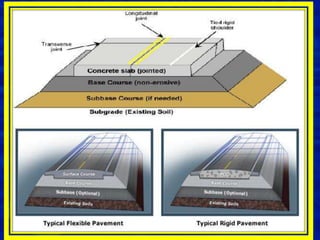


Concrete pavement components include concrete slabs of a determined thickness, joints to control cracking, tie bars at joints to hold slabs together, and dowel bars at transverse joints to allow load transfer between slabs. A stable base layer, optional subbase layer, and subgrade provide the foundation. Proper preparation of these layers and placement of reinforcement like tie and dowel bars according to specifications is important for a strong, durable pavement. Both rigid concrete and flexible asphalt pavements are designed based on factors like traffic levels, soil properties, environment, and desired reliability and service life.