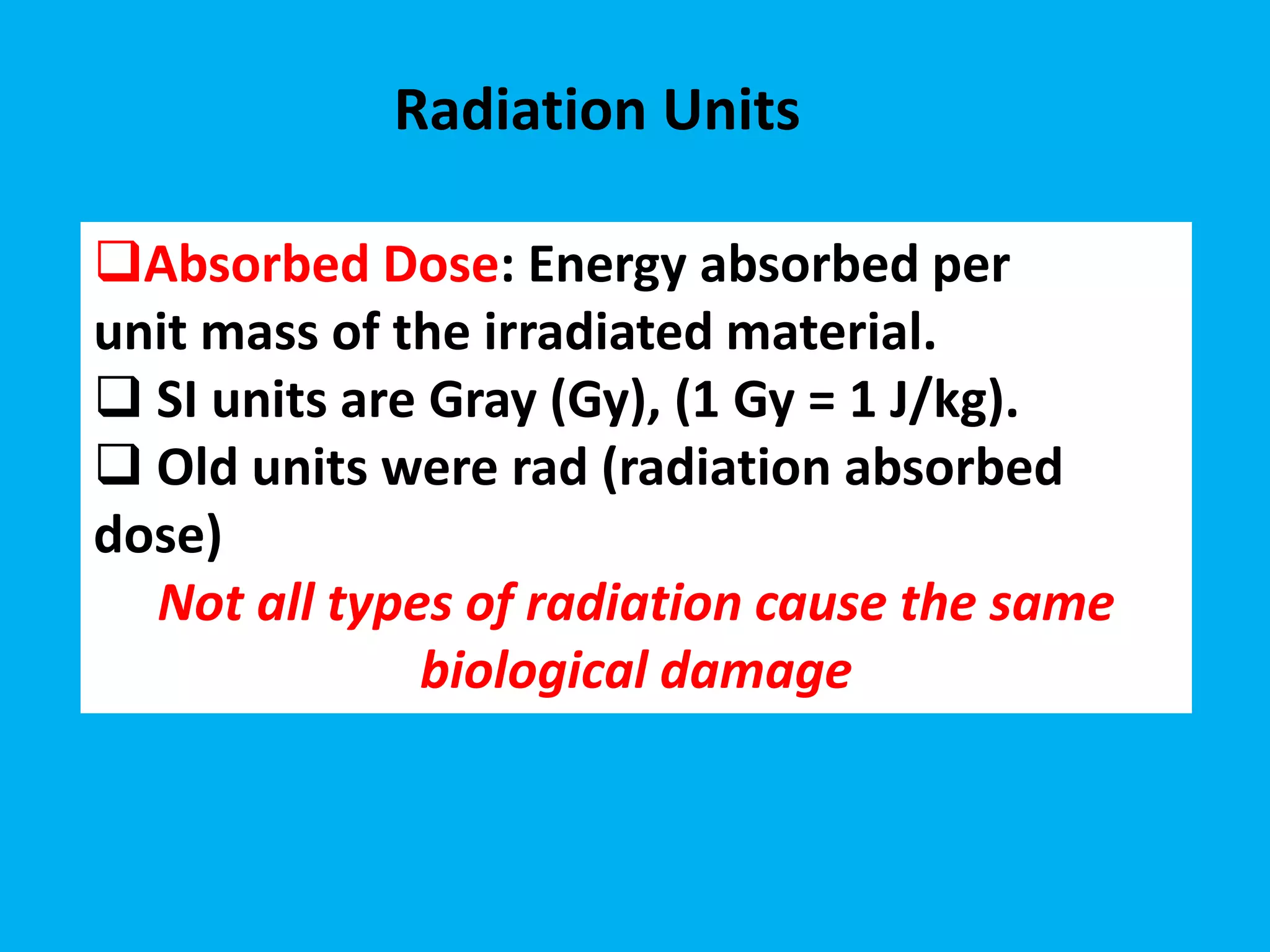
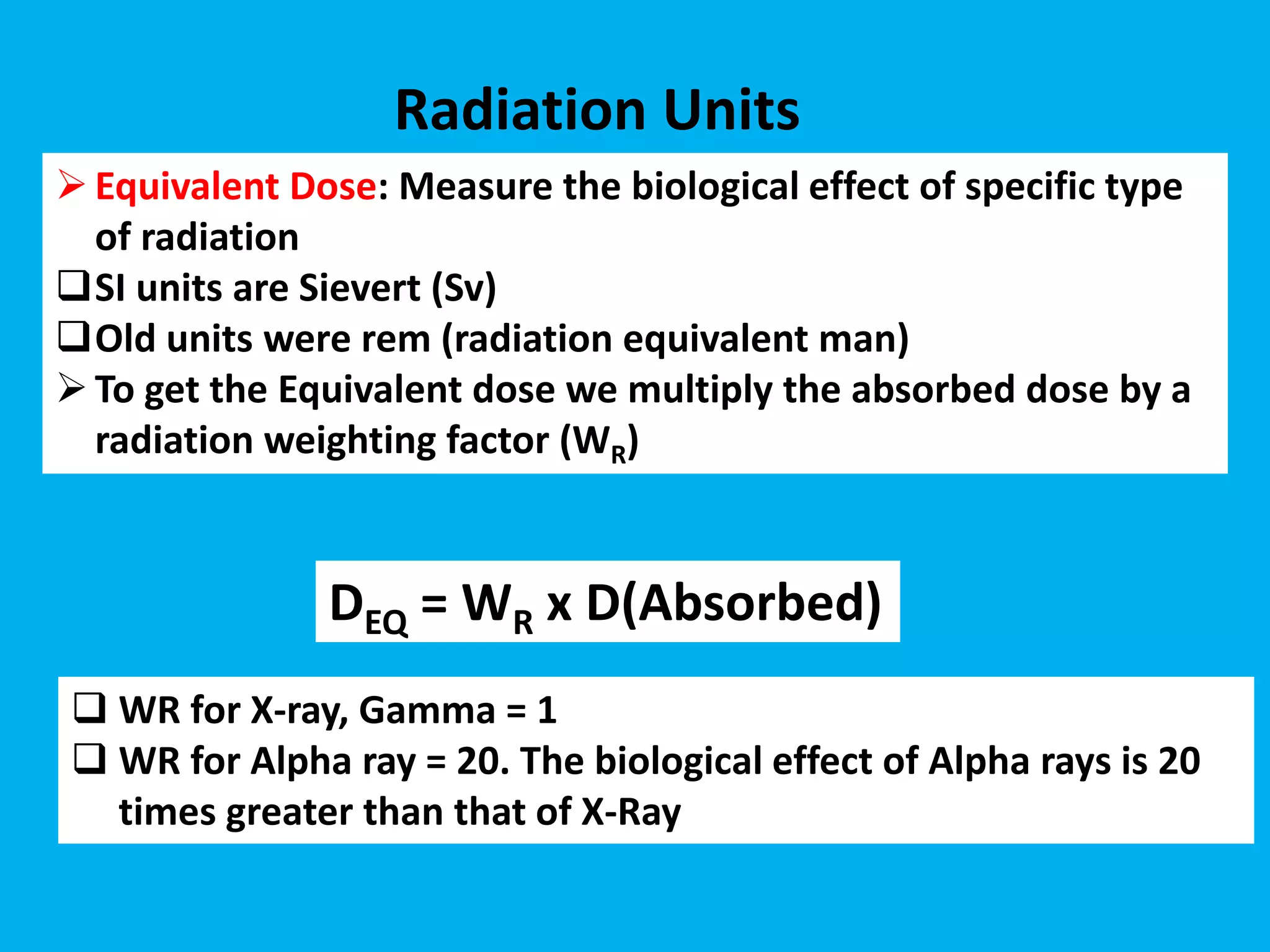
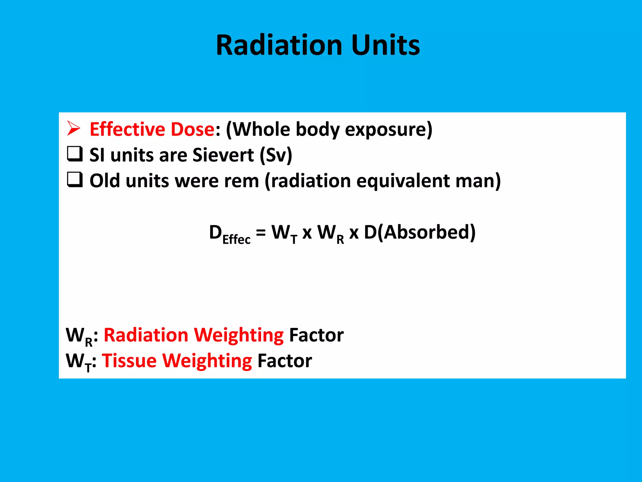
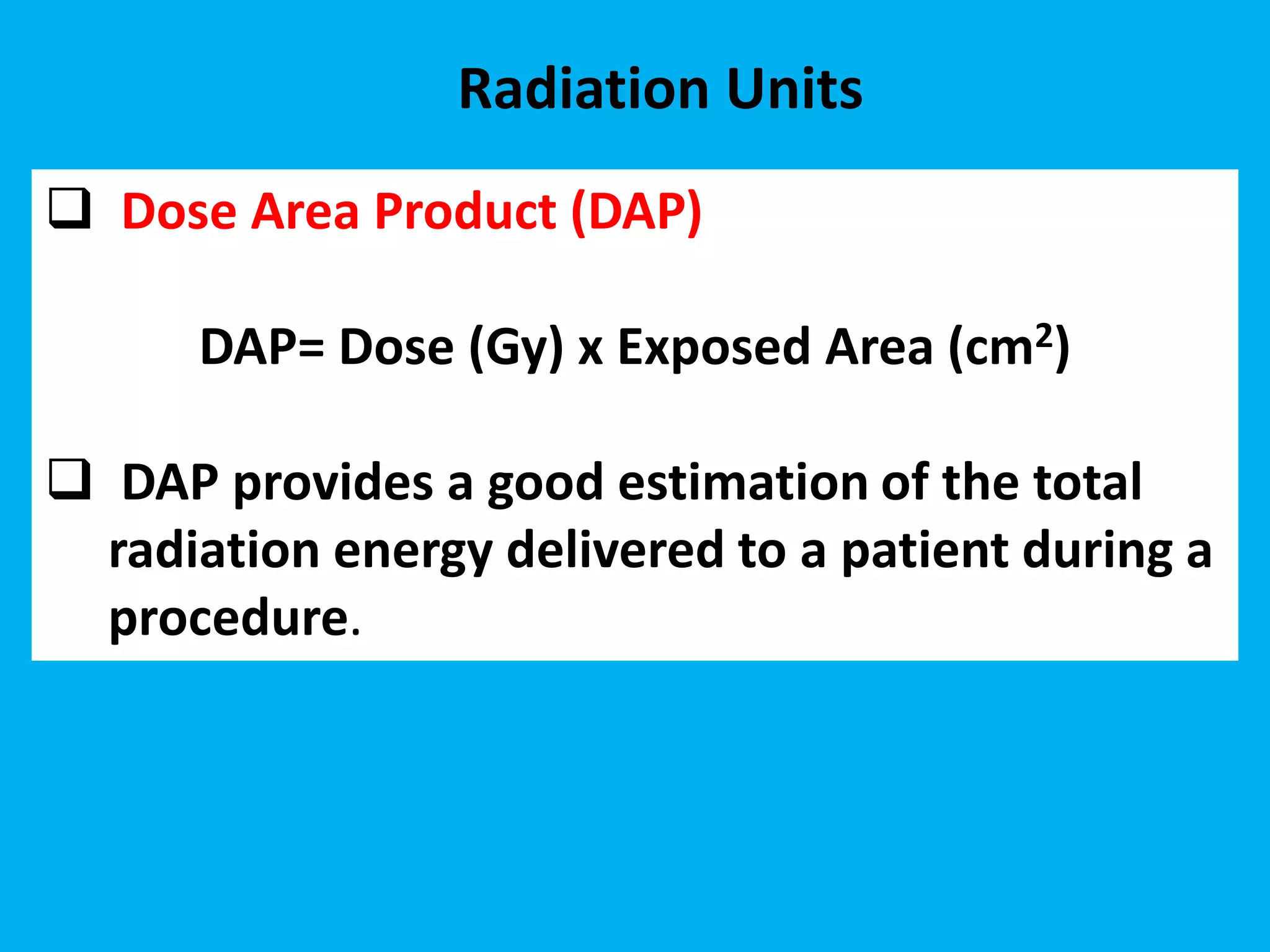
Patient dose management in
angiography
Dr. Naima SENHOU
King Saud bin Abdulaziz University
for Health Sciences
Ministry of National Guard Health
Affairs KAMC-Riyadh
12/11/2019
Radiation risks (Patients)
Skin burn is a well-documented radiation induced effect
•But there are several other important
deterministic effects than can occur:
• Lens opacities and cataract
• Affected fertility
• Reduced count in White Blood Cells
Exposure: Ionization (charge) produced
by photons per unit mass in air
SI units are C/kg
Conventional is the Roentgen R
1 R = 2.58×10⁻⁴ C/kg
if the exposure = 1 R then the dose is ~
8.76 mGy In Air
Radiation Units
Absorbed Dose: Energy absorbed per
unit mass of the irradiated material.
 SI units are Gray (Gy), (1 Gy = 1 J/kg).
 Old units were rad (radiation absorbed
dose)
Not all types of radiation cause the same
biological damage
Radiation Units
Equivalent Dose: Measure the biological effect of specific type
of radiation
SI units are Sievert (Sv)
Old units were rem (radiation equivalent man)
To get the Equivalent dose we multiply the absorbed dose by a
radiation weighting factor (WR)
Radiation Units
 WR for X-ray, Gamma = 1
 WR for Alpha ray = 20. The biological effect of Alpha rays is 20
times greater than that of X-Ray
DEQ = WR x D(Absorbed)
Radiation Units
 Effective Dose: (Whole body exposure)
 SI units are Sievert (Sv)
 Old units were rem (radiation equivalent man)
DEffec = WT x WR x D(Absorbed)
WR: Radiation Weighting Factor
WT: Tissue Weighting Factor
Radiation Units
Tissue Weighting and radiation Factors (Update, ICRP
2007)
 Dose Area Product (DAP)
DAP= Dose (Gy) x Exposed Area (cm2)
 DAP provides a good estimation of the total
radiation energy delivered to a patient during a
procedure.
Radiation Units
DAP: (Dose Area Product)
 Used with Fluoroscopy machines
DAP Units
mGy x cm2
mRad x cm2
Gy = 100 rad
mGy = 0.001 Gy
mGy = 100 mRad
Radiation Units
where μ is the linear attenuation coefficient and X is the distance the photon has to travel
through the tissue.
The amount of radiation that passes through tissue is given by the Beer-Lambert law,
which says that
Intensity(out) = Intensity(in) * e -(μ * X)
Attenuation and Dose
The thicker the patient or body part, the fewer photons escape to the other side. We
need a certain number of photons to produce an image
The use of iodine compounds was initially related to low toxicity and excellent radio-opacity
rather than physical considerations. However, it was also fortunate that iodine compounds
possess physical properties which make them better contrast agents than compounds with
higher atomic number.
The K-edge of iodine is 33.2 keV. At photon energies slightly above this, iodine actually has
greater attenuating properties for x-rays than the same mass of lead.
iodine compounds as contract agent
Iodine k-edge
The k-edge represents the
energy needed to eject a K-
shell electron (the innermost
and most strongly bound
electrons).
Outer shell electrons have
absorption edges but these
are much too low energy to
be relevant.
Tissue Contrast
If all different types of tissue stopped x-rays in the same way, then we would have no picture
In soft tissues, the dominant elements (e.g. C, H, O, and N) have very low K-edges, in the
range of a few keV. While these elements do contribute to the photoelectric effect and
attenuate low energy x-rays, there is no relevant k-edge with its substantial change in
attenuation.
However, the elements iodine and barium have K-edges around 30-40 keV, right in the
middle of the x-ray beam spectrum. Thus, soft tissues with even a small amount of iodine
will have a much stronger x-ray stopping power than those without.
The presence of materials with high k-edges such as iodine or barium improve the
contrast at higher kV, but contrast is still better at lower kV.
No change with water and calcium
The interventional reference point (IRP) was introduced by the International
Electrotechnical Commission (IEC) in 2000. It is defined to be located at 15 cm from the
isocentre of the C-arm toward the X-ray tube (IEC, 2000)
This point is fixed relative to the X-ray tube and is independent of the patient variation.
The IRP is fixed relative to the X-ray tube as it is always at a constant distance from the
isocentre, which may represent a position on the patient’s skin or a point inside or outside
of the patient’s body The IRP rarely represents the exact location of the patient’s skin over
clinical procedures.
Using accumulated doses at IRP locations tends to result in higher than actual
peak skin doses and thus overestimates the radiation risk to patients.
The interventional reference point (IRP)
17
Factors that influence Patient Absorbed
Dose
• Equipment-related factors
– Movement capabilities of C-arm, X ray source, image
receptor
– Field-of-view size
– Collimator position
– Beam filtration
– Angiography pulse rate and acquisition frame rate
– Angiography and acquisition input dose rates
– Automatic dose-rate control including beam energy
management options
– X ray photon energy spectra
– Software image filters
– Preventive maintenance and calibration
– Quality control
18
Factors that influence Patient
Absorbed Dose
 Minimise beam-on time
 Maximise source to patient distance
 Optimize kVp
 Collimate to region of interest
 Use last image hold and pulsed angiograohy
 Review real time image recordings
 Minimise use of magnification modes
Methods to minimise radiation dose to patients during a angiography
procedure are:
Patient Position
• The patient should be placed away from the radiation source to lower the skin dose
• The image detector should be placed close to the patient to lower the necessary
dose
 less geometric blurring
•The tube should always be positioned under the table (under couch configuration)
 less scatter towards the personnel’s eyes
•Keep the patient’s extremities out of the beam
Tube Angulation
• The use of steep angulations should be minimized and used only if necessary
• Each 3 cm additional tissue doubles the dose to the patient (factor of ~10
each 10 cm)
Using small angulations actually has the potential to reduce the peak skin dose of the patient
• Moving the X-ray beam to different areas of the patient’s body during the procedures lowers
the peak skin dose
• Good practice: every 30 minutes, change the beam angle
Magnification will increase the patient dose (beam energy is condensed to a smaller
area)
• Use the largest Field of view (FOV) possible for the procedure being performed.
The difference in skin dose between the larger FOVs and the smallest is a factor of ~4
•In modern systems, there is a "Live Zoom“ feature without additional radiation and
without significant degradation of the image.
Magnification
Collimation
A ‘collimator’ is an adjustable lead shutter located at the exit of the X-ray source that can be
closed down to limit the irradiated area
• Appropriate collimation should be used for the imaging task
 this lowers both the patient’s dose and the staff’s
• Modern systems should be equipped with virtual collimation
System Settings
• It is important to get to know your system and its options
• Make sure to use the lowest dose setting when possible
• Talk with the manufacturer/technician to set the initial dose setting to ‘low dose’
 increase when necessary instead of lowering when possible (less chance to forget)
• Use the proper frame rate, lower where possible
• Use the proper acquisition program
• Make sure when buying a new system that it has proper filtration
 Cu filters out the low energy X-rays, lowering skin dose
Dose estimation dose management
How can we estimate the
dose received by the
patient???
National Council on Radiation Protection & Measurements( NCRP) 168
Fluoroscopically guided
interventional (FGI)
procedures
kerma-area product (PKA)
 This highlights the need for dose standardisation and to further extend dose
reduction, while maintaining diagnostic quality of the X-ray images or procedures.
 DRLs can be set based on local dosimetry or practice data, or can be based on
published values that are appropriate for the local circumstances.
 Diagnostic reference levels (DRLs) are a practical tool to promote optimization.
 DRLs are general guideline for clinical operations and do not apply directly to
individual patients and examinations.
 DRLs should be examination/procedure specific
 Different DRLs can also be set for each hospital, district, region or country.
 National DRLs (NDRLs) are usually set based on a wide scale survey of the median
doses representing typical practice for specific patient groups (e.g. adults or
children).
Diagnostic reference levels (DRLs
Picture archiving and communication system (PACS)
How does kV affect iodine enhancement?
Relative to iodine
attenuation 120 kV
– 70% higher at 80 kV
– 25% higher at 100 kV
THANK YOU

patient dose management in angiography king saud unversity.pdf

  • 1.
    Patient dose managementin angiography Dr. Naima SENHOU King Saud bin Abdulaziz University for Health Sciences Ministry of National Guard Health Affairs KAMC-Riyadh 12/11/2019
  • 3.
    Radiation risks (Patients) Skinburn is a well-documented radiation induced effect •But there are several other important deterministic effects than can occur: • Lens opacities and cataract • Affected fertility • Reduced count in White Blood Cells
  • 4.
    Exposure: Ionization (charge)produced by photons per unit mass in air SI units are C/kg Conventional is the Roentgen R 1 R = 2.58×10⁻⁴ C/kg if the exposure = 1 R then the dose is ~ 8.76 mGy In Air Radiation Units
  • 5.
    Absorbed Dose: Energyabsorbed per unit mass of the irradiated material.  SI units are Gray (Gy), (1 Gy = 1 J/kg).  Old units were rad (radiation absorbed dose) Not all types of radiation cause the same biological damage Radiation Units
  • 6.
    Equivalent Dose: Measurethe biological effect of specific type of radiation SI units are Sievert (Sv) Old units were rem (radiation equivalent man) To get the Equivalent dose we multiply the absorbed dose by a radiation weighting factor (WR) Radiation Units  WR for X-ray, Gamma = 1  WR for Alpha ray = 20. The biological effect of Alpha rays is 20 times greater than that of X-Ray DEQ = WR x D(Absorbed)
  • 7.
  • 8.
     Effective Dose:(Whole body exposure)  SI units are Sievert (Sv)  Old units were rem (radiation equivalent man) DEffec = WT x WR x D(Absorbed) WR: Radiation Weighting Factor WT: Tissue Weighting Factor Radiation Units
  • 9.
    Tissue Weighting andradiation Factors (Update, ICRP 2007)
  • 10.
     Dose AreaProduct (DAP) DAP= Dose (Gy) x Exposed Area (cm2)  DAP provides a good estimation of the total radiation energy delivered to a patient during a procedure. Radiation Units
  • 11.
    DAP: (Dose AreaProduct)  Used with Fluoroscopy machines DAP Units mGy x cm2 mRad x cm2 Gy = 100 rad mGy = 0.001 Gy mGy = 100 mRad Radiation Units
  • 12.
    where μ isthe linear attenuation coefficient and X is the distance the photon has to travel through the tissue. The amount of radiation that passes through tissue is given by the Beer-Lambert law, which says that Intensity(out) = Intensity(in) * e -(μ * X) Attenuation and Dose The thicker the patient or body part, the fewer photons escape to the other side. We need a certain number of photons to produce an image
  • 13.
    The use ofiodine compounds was initially related to low toxicity and excellent radio-opacity rather than physical considerations. However, it was also fortunate that iodine compounds possess physical properties which make them better contrast agents than compounds with higher atomic number. The K-edge of iodine is 33.2 keV. At photon energies slightly above this, iodine actually has greater attenuating properties for x-rays than the same mass of lead. iodine compounds as contract agent
  • 14.
    Iodine k-edge The k-edgerepresents the energy needed to eject a K- shell electron (the innermost and most strongly bound electrons). Outer shell electrons have absorption edges but these are much too low energy to be relevant.
  • 15.
    Tissue Contrast If alldifferent types of tissue stopped x-rays in the same way, then we would have no picture In soft tissues, the dominant elements (e.g. C, H, O, and N) have very low K-edges, in the range of a few keV. While these elements do contribute to the photoelectric effect and attenuate low energy x-rays, there is no relevant k-edge with its substantial change in attenuation. However, the elements iodine and barium have K-edges around 30-40 keV, right in the middle of the x-ray beam spectrum. Thus, soft tissues with even a small amount of iodine will have a much stronger x-ray stopping power than those without. The presence of materials with high k-edges such as iodine or barium improve the contrast at higher kV, but contrast is still better at lower kV. No change with water and calcium
  • 16.
    The interventional referencepoint (IRP) was introduced by the International Electrotechnical Commission (IEC) in 2000. It is defined to be located at 15 cm from the isocentre of the C-arm toward the X-ray tube (IEC, 2000) This point is fixed relative to the X-ray tube and is independent of the patient variation. The IRP is fixed relative to the X-ray tube as it is always at a constant distance from the isocentre, which may represent a position on the patient’s skin or a point inside or outside of the patient’s body The IRP rarely represents the exact location of the patient’s skin over clinical procedures. Using accumulated doses at IRP locations tends to result in higher than actual peak skin doses and thus overestimates the radiation risk to patients. The interventional reference point (IRP)
  • 17.
    17 Factors that influencePatient Absorbed Dose • Equipment-related factors – Movement capabilities of C-arm, X ray source, image receptor – Field-of-view size – Collimator position – Beam filtration – Angiography pulse rate and acquisition frame rate – Angiography and acquisition input dose rates – Automatic dose-rate control including beam energy management options – X ray photon energy spectra – Software image filters – Preventive maintenance and calibration – Quality control
  • 18.
    18 Factors that influencePatient Absorbed Dose  Minimise beam-on time  Maximise source to patient distance  Optimize kVp  Collimate to region of interest  Use last image hold and pulsed angiograohy  Review real time image recordings  Minimise use of magnification modes Methods to minimise radiation dose to patients during a angiography procedure are:
  • 19.
    Patient Position • Thepatient should be placed away from the radiation source to lower the skin dose • The image detector should be placed close to the patient to lower the necessary dose  less geometric blurring •The tube should always be positioned under the table (under couch configuration)  less scatter towards the personnel’s eyes •Keep the patient’s extremities out of the beam
  • 20.
    Tube Angulation • Theuse of steep angulations should be minimized and used only if necessary • Each 3 cm additional tissue doubles the dose to the patient (factor of ~10 each 10 cm) Using small angulations actually has the potential to reduce the peak skin dose of the patient • Moving the X-ray beam to different areas of the patient’s body during the procedures lowers the peak skin dose • Good practice: every 30 minutes, change the beam angle
  • 21.
    Magnification will increasethe patient dose (beam energy is condensed to a smaller area) • Use the largest Field of view (FOV) possible for the procedure being performed. The difference in skin dose between the larger FOVs and the smallest is a factor of ~4 •In modern systems, there is a "Live Zoom“ feature without additional radiation and without significant degradation of the image. Magnification
  • 22.
    Collimation A ‘collimator’ isan adjustable lead shutter located at the exit of the X-ray source that can be closed down to limit the irradiated area • Appropriate collimation should be used for the imaging task  this lowers both the patient’s dose and the staff’s • Modern systems should be equipped with virtual collimation
  • 23.
    System Settings • Itis important to get to know your system and its options • Make sure to use the lowest dose setting when possible • Talk with the manufacturer/technician to set the initial dose setting to ‘low dose’  increase when necessary instead of lowering when possible (less chance to forget) • Use the proper frame rate, lower where possible • Use the proper acquisition program • Make sure when buying a new system that it has proper filtration  Cu filters out the low energy X-rays, lowering skin dose
  • 24.
    Dose estimation dosemanagement How can we estimate the dose received by the patient???
  • 25.
    National Council onRadiation Protection & Measurements( NCRP) 168 Fluoroscopically guided interventional (FGI) procedures kerma-area product (PKA)
  • 30.
     This highlightsthe need for dose standardisation and to further extend dose reduction, while maintaining diagnostic quality of the X-ray images or procedures.  DRLs can be set based on local dosimetry or practice data, or can be based on published values that are appropriate for the local circumstances.  Diagnostic reference levels (DRLs) are a practical tool to promote optimization.  DRLs are general guideline for clinical operations and do not apply directly to individual patients and examinations.  DRLs should be examination/procedure specific  Different DRLs can also be set for each hospital, district, region or country.  National DRLs (NDRLs) are usually set based on a wide scale survey of the median doses representing typical practice for specific patient groups (e.g. adults or children). Diagnostic reference levels (DRLs
  • 31.
  • 32.
    Picture archiving andcommunication system (PACS)
  • 33.
    How does kVaffect iodine enhancement? Relative to iodine attenuation 120 kV – 70% higher at 80 kV – 25% higher at 100 kV
  • 69.