Downloaded 367 times
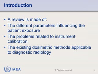


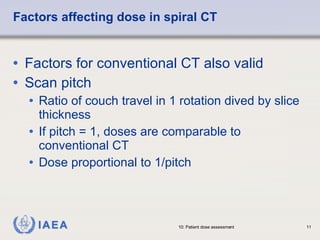
![Essential parameters influencing patient exposure Tube voltage Tube current Effective filtration Exposure time Field size Kerma rate [mGy/min] [min] Kerma [ Gy] [m 2 ] Area exposure product [ Gy m 2 ] } } }](https://image.slidesharecdn.com/l10patientdose-1223412968377320-8/85/L10-Patient-Dose-6-320.jpg)


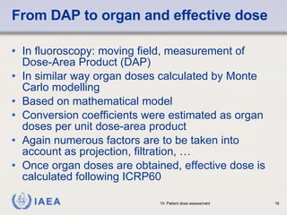

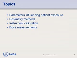
![Calibration of an instrument Establish Calibration Reference Conditions (CRC) [type and energy of radiation, SDD, rate, ...] Compare response of your instrument with that of another instrument (absolute or calibrated) Get the calibration factor [appropriate unit] Response of the instrument to be calibrated f the reference instrument Response o F ](https://image.slidesharecdn.com/l10patientdose-1223412968377320-8/85/L10-Patient-Dose-18-320.jpg)


This document discusses patient dose assessment in diagnostic and interventional radiology. It covers parameters that influence patient exposure like tube voltage and current. It also discusses different dosimetry methods like measuring entrance surface dose, dose area product, and computed tomography dose index. Finally, it addresses instrument calibration and how to accurately measure dose indicators through techniques like thermoluminescent dosimetry.


