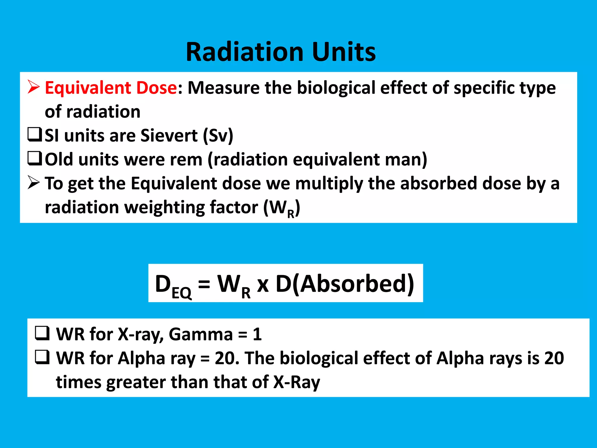
King Saud bin Abdulaziz University for
Health Sciences
Ministry of National Guard Health Affairs
KAMC-Riyadh
Radioprotection in Angiography
Dr. Naima SENHOU
Patients have their DAP value, you
have your dosimeter!
1. Optimization,
2. justification,
3. Limitation.
General Principles of Radiation Protection
Biologic Effects of Radiation
 Deterministic injuries
 When large numbers of cells are damaged and die
immediately or shortly after irradiation. Units of Gy.
 There is a threshold dose for visible post procedure
injury ranging from erythema to skin necrosis.
 Stochastic injuries
 Post radiation damage, cell descendants are
clinically important. Higher dose, the more likely the
process.
 There is a linear non-threshold dose identifiable for
radiation-induced neoplasm and heritable genetic
defects. This is in units of Sv.
NCRP Staff Exposure Limits
 Whole Body*
(50 mSv)/yr
 Eyes*
(20mSv)/ yr
 Skin /Extremities-500 mSv/yr
 Pregnant Women
(0.5 mSv)/mo
 Public
(1.0 mSv)/yr Cataract in eye of interventionist after
repeated use of over table x-ray tube
Staff radioprotection in angiography
TIME
• Take foot off fluoro pedal if physician is not viewing the TV monitor
• Use last image hold (freeze frame)
• Five-minute timer
• Use pulsed fluoro instead of continuous fluoro
• Pulsed Low-Dose provides further reduction with respect to Normal
Radiation Protection
DISTANCE
- One step back from tableside:
cuts exposure by factor of 4
- Move Image Int. close to patient:
less patient skin exposure less
scatter
- Source to Skin Distance (SSD):
38 cm for stationary fluoroscopes
30 cm for mobile fluoroscopes
Radiation Protection
Distance
effect
Distance
from Beam 1 step 2 steps 3 steps 4 steps
Relative
Exposure Rate 100 25 11 6
Step back for
safety
Keep your hands out of the radiation field
Put the detector as close as possible to the patient
If not needed in the room, leave the room. Try not to
be standing next to the patient
Use power injectors for contrast material injections
when feasible
Ergonomics in the room
Place the monitors away from the x-ray source
Analysis of danger
Distance
X-ray Tube Position
• Position the X-ray tube under the
patient not above the patient.
• The largest amount of scatter
radiation is produced where the
x-ray beam enters the patient.
• By positioning the x-ray tube
below the patient, you decrease
the amount of scatter radiation
that reaches your upper body.
Radiation Protection
Shielding
Increasing the amount of shielding around a source of
radiation will decrease the amount of radiation exposure.
To avoid scatter Be sure to shield all directions.
Shielding
-
+
Radiation Protection
• SHIELDING
- Lead aprons: cut exposure by factor of 20
- Proper storage (hanging vs. folding)
Radiation Protection
Protection tools
curtain thyroid shield
Eye goggles Lead Apron
Radiation Protection
Portable leaded shield
proper storage of radiation protection devices-
Lead apron
Take Proper Care
of Your Apron
The high occupational exposures in interventional radiology require the use of
robust and adequate monitoring arrangements for staff
• Personal dosimeters are typically thermoluminescent dosimeters (TLDs)
• It is recommended (sometimes obliged) to wear two dosimeters:
1. Under-apron worn at breast or waist level >>>> gives an estimate of effective dose
and confirms the lead apron is being worn (properly)
2. Over-apron worn at the collar level>>>> provides an estimate of the eye lens dose
• The monitoring period should be one month, and should not exceed three months
Personal dosimeters
Radiation Protection
Factors influencing dose:
patient size
 kVp, mA and time
tube - patient distance (SSD)
Image Intensifier - patient distance
image magnification vs. patient dose
 x-ray field collimation
oblique's vs. perpendicular views
Radiation Protection
 Standard Operating Procedures
- each clinical protocol / procedure
- modes of operation, image recording
- emphasis on minimizing duration
- risk / benefit on a case-by-case basis
 Equipment quality control
- periodic PMs
- prompt calibrations
- post radiation output values
- check aprons, shields, gloves annually
Patient dose management in
angiography
Dr. Naima SENHOU
King Saud bin Abdulaziz University
for Health Sciences
Ministry of National Guard Health
Affairs KAMC-Riyadh
11/15/2020
Radiation risks (Patients)
Skin burn is a well-documented radiation induced effect
•But there are several other important
deterministic effects than can occur:
• Lens opacities and cataract
• Affected fertility
• Reduced count in White Blood Cells
Exposure: Ionization (charge) produced
by photons per unit mass in air
SI units are C/kg
Conventional is the Roentgen R
1 R = 2.58×10⁻⁴ C/kg
if the exposure = 1 R then the dose is ~
8.76 mGy In Air
Radiation Units
Absorbed Dose: Energy absorbed per
unit mass of the irradiated material.
 SI units are Gray (Gy), (1 Gy = 1 J/kg).
 Old units were rad (radiation absorbed
dose)
Not all types of radiation cause the same
biological damage
Radiation Units
Equivalent Dose: Measure the biological effect of specific type
of radiation
SI units are Sievert (Sv)
Old units were rem (radiation equivalent man)
To get the Equivalent dose we multiply the absorbed dose by a
radiation weighting factor (WR)
Radiation Units
 WR for X-ray, Gamma = 1
 WR for Alpha ray = 20. The biological effect of Alpha rays is 20
times greater than that of X-Ray
DEQ = WR x D(Absorbed)
Radiation Units
 Effective Dose: (Whole body exposure)
 SI units are Sievert (Sv)
 Old units were rem (radiation equivalent man)
DEffec = WT x WR x D(Absorbed)
WR: Radiation Weighting Factor
WT: Tissue Weighting Factor
Radiation Units
 Dose Area Product (DAP)
DAP= Dose (Gy) x Exposed Area (cm2)
 DAP provides a good estimation of the total
radiation energy delivered to a patient during a
procedure.
Radiation Units
DAP: (Dose Area Product)
 Used with Fluoroscopy machines
DAP Units
mGy x cm2
mRad x cm2
Gy = 100 rad
mGy = 0.001 Gy
mGy = 100 mRad
Radiation Units
where μ is the linear attenuation coefficient and X is the distance the photon has to travel
through the tissue.
The amount of radiation that passes through tissue is given by the Beer-Lambert law,
which says that
Intensity(out) = Intensity(in) * e -(μ * X)
Attenuation and Dose
The thicker the patient or body part, the fewer photons escape to the other side. We
need a certain number of photons to produce an image
The use of iodine compounds was initially related to low toxicity and excellent radio-opacity
rather than physical considerations. However, it was also fortunate that iodine compounds
possess physical properties which make them better contrast agents than compounds with
higher atomic number.
The K-edge of iodine is 33.2 keV. At photon energies slightly above this, iodine actually has
greater attenuating properties for x-rays than the same mass of lead.
iodine compounds as contract agent
• Total Air Kerma (mGy): "kinetic energy released in material",
• Procedural cumulative dose at the interventional reference point (dose delivered to air)
• Reference point: usually along central ray of x-ray beam 15cm back from isocenter
• Measured and displayed on all fluoroscopic equipment sold in USA after 2006
• Can be used to monitor thresholds for deterministic effects of radiation exposure
• Peak Skin Dose (mGy):
• Maximum dose received by any local area of the skin
• Not measured directly
• Derived from total air kerma using a variety of calculations, taking into account angles & projections
of x-Ray beams (will require a physicist to get involved to calculate the accurate dose)
• Less than total air kerma for most (but not all) procedures
• Determines deterministic effects of radiation exposure
o The Joint Commission identifies a cumulative peak skin dose > 15 Gy as a sentinel event (cumulative peak skin dose over
6-12 months)
o (The Joint Commission. Radiation overdose as a reviewable sentinel event.
http://www.jointcommission.org/assets/1/18/Radiation_Overdose.pdf Accessed September 2013)
Radiation Exposure: Units of Measurement
The interventional reference point (IRP) was introduced by the International
Electrotechnical Commission (IEC) in 2000. It is defined to be located at 15 cm from the
isocentre of the C-arm toward the X-ray tube (IEC, 2000)
This point is fixed relative to the X-ray tube and is independent of the patient variation.
The IRP is fixed relative to the X-ray tube as it is always at a constant distance from the
isocentre, which may represent a position on the patient’s skin or a point inside or outside
of the patient’s body The IRP rarely represents the exact location of the patient’s skin over
clinical procedures.
Using accumulated doses at IRP locations tends to result in higher than actual
peak skin doses and thus overestimates the radiation risk to patients.
The interventional reference point (IRP)
38
Factors that influence Patient Absorbed
Dose
• Equipment-related factors
– Movement capabilities of C-arm, X ray source, image
receptor
– Field-of-view size
– Collimator position
– Beam filtration
– Angiography pulse rate and acquisition frame rate
– Angiography and acquisition input dose rates
– Automatic dose-rate control including beam energy
management options
– X ray photon energy spectra
– Software image filters
– Preventive maintenance and calibration
– Quality control
39
Factors that influence Patient
Absorbed Dose
 Minimise beam-on time
 Maximise source to patient distance
 Optimize kVp
 Collimate to region of interest
 Use last image hold and pulsed angiograohy
 Review real time image recordings
 Minimise use of magnification modes
Methods to minimise radiation dose to patients during a angiography
procedure are:
Patient Position
• The patient should be placed away from the radiation source to lower the skin dose
• The image detector should be placed close to the patient to lower the necessary
dose
 less geometric blurring
•The tube should always be positioned under the table (under couch configuration)
 less scatter towards the personnel’s eyes
•Keep the patient’s extremities out of the beam
Tube Angulation
• The use of steep angulations should be minimized and used only if necessary
• Each 3 cm additional tissue doubles the dose to the patient (factor of ~10
each 10 cm)
Using small angulations actually has the potential to reduce the peak skin dose of the patient
• Moving the X-ray beam to different areas of the patient’s body during the procedures lowers
the peak skin dose
• Good practice: every 30 minutes, change the beam angle
Magnification will increase the patient dose (beam energy is condensed to a smaller
area)
• Use the largest Field of view (FOV) possible for the procedure being performed.
The difference in skin dose between the larger FOVs and the smallest is a factor of ~4
•In modern systems, there is a "Live Zoom“ feature without additional radiation and
without significant degradation of the image.
Magnification
Collimation
A ‘collimator’ is an adjustable lead shutter located at the exit of the X-ray source that can be
closed down to limit the irradiated area
• Appropriate collimation should be used for the imaging task
 this lowers both the patient’s dose and the staff’s
• Modern systems should be equipped with virtual collimation
System Settings
• It is important to get to know your system and its options
• Make sure to use the lowest dose setting when possible
• Talk with the manufacturer/technician to set the initial dose setting to ‘low dose’
 increase when necessary instead of lowering when possible (less chance to forget)
• Use the proper frame rate, lower where possible
• Use the proper acquisition program
• Make sure when buying a new system that it has proper filtration
 Cu filters out the low energy X-rays, lowering skin dose
Dose estimation dose management
How can we estimate the
dose received by the
patient???
National Council on Radiation Protection & Measurements( NCRP) 168
Fluoroscopically guided
interventional (FGI)
procedures
kerma-area product (PKA)
 This highlights the need for dose standardisation and to further extend dose
reduction, while maintaining diagnostic quality of the X-ray images or procedures.
 DRLs can be set based on local dosimetry or practice data, or can be based on
published values that are appropriate for the local circumstances.
 Diagnostic reference levels (DRLs) are a practical tool to promote optimization.
 DRLs are general guideline for clinical operations and do not apply directly to
individual patients and examinations.
 DRLs should be examination/procedure specific
 Different DRLs can also be set for each hospital, district, region or country.
 National DRLs (NDRLs) are usually set based on a wide scale survey of the median
doses representing typical practice for specific patient groups (e.g. adults or
children).
Diagnostic reference levels (DRLs
Picture archiving and communication system (PACS)
How does kV affect iodine enhancement?
Relative to iodine
attenuation 120 kV
– 70% higher at 80 kV
– 25% higher at 100 kV
Procedure Related Issues to Minimize Exposure
to Patient and Operator
• Utilize radiation only when
imaging is necessary
• Minimize use of cine
• Minimize steep angle X-ray
beam
• Minimize use of magnification
modes
• Minimize frame rate of
fluoroscopy and cine
• Keep the image receptor close
to the patient
• Utilize collimation to the fullest
extent possible
• Monitor real time radiation dose
DRAPED:
• D-distance: inverse square law
• R-receptor: keep image receptor
close to patient and collimate
• A-angles: avoid steep angles
• P-pedal: keep foot off pedal
except when looking at the
monitor
• E: extremities-keep
patient/operator extremities out
of the beam
• D-dose: limit cine, adjust frame
rate, where personal dosimeter
THANK YOU

Radioprotection in Angiography

  • 1.
    King Saud binAbdulaziz University for Health Sciences Ministry of National Guard Health Affairs KAMC-Riyadh Radioprotection in Angiography Dr. Naima SENHOU
  • 2.
    Patients have theirDAP value, you have your dosimeter! 1. Optimization, 2. justification, 3. Limitation. General Principles of Radiation Protection
  • 3.
    Biologic Effects ofRadiation  Deterministic injuries  When large numbers of cells are damaged and die immediately or shortly after irradiation. Units of Gy.  There is a threshold dose for visible post procedure injury ranging from erythema to skin necrosis.  Stochastic injuries  Post radiation damage, cell descendants are clinically important. Higher dose, the more likely the process.  There is a linear non-threshold dose identifiable for radiation-induced neoplasm and heritable genetic defects. This is in units of Sv.
  • 4.
    NCRP Staff ExposureLimits  Whole Body* (50 mSv)/yr  Eyes* (20mSv)/ yr  Skin /Extremities-500 mSv/yr  Pregnant Women (0.5 mSv)/mo  Public (1.0 mSv)/yr Cataract in eye of interventionist after repeated use of over table x-ray tube
  • 5.
  • 7.
    TIME • Take footoff fluoro pedal if physician is not viewing the TV monitor • Use last image hold (freeze frame) • Five-minute timer • Use pulsed fluoro instead of continuous fluoro • Pulsed Low-Dose provides further reduction with respect to Normal Radiation Protection
  • 8.
    DISTANCE - One stepback from tableside: cuts exposure by factor of 4 - Move Image Int. close to patient: less patient skin exposure less scatter - Source to Skin Distance (SSD): 38 cm for stationary fluoroscopes 30 cm for mobile fluoroscopes Radiation Protection
  • 9.
    Distance effect Distance from Beam 1step 2 steps 3 steps 4 steps Relative Exposure Rate 100 25 11 6 Step back for safety
  • 10.
    Keep your handsout of the radiation field Put the detector as close as possible to the patient If not needed in the room, leave the room. Try not to be standing next to the patient Use power injectors for contrast material injections when feasible Ergonomics in the room Place the monitors away from the x-ray source Analysis of danger Distance
  • 11.
    X-ray Tube Position •Position the X-ray tube under the patient not above the patient. • The largest amount of scatter radiation is produced where the x-ray beam enters the patient. • By positioning the x-ray tube below the patient, you decrease the amount of scatter radiation that reaches your upper body. Radiation Protection
  • 12.
    Shielding Increasing the amountof shielding around a source of radiation will decrease the amount of radiation exposure. To avoid scatter Be sure to shield all directions. Shielding - + Radiation Protection
  • 13.
    • SHIELDING - Leadaprons: cut exposure by factor of 20 - Proper storage (hanging vs. folding) Radiation Protection
  • 14.
    Protection tools curtain thyroidshield Eye goggles Lead Apron Radiation Protection Portable leaded shield
  • 15.
    proper storage ofradiation protection devices- Lead apron Take Proper Care of Your Apron
  • 16.
    The high occupationalexposures in interventional radiology require the use of robust and adequate monitoring arrangements for staff • Personal dosimeters are typically thermoluminescent dosimeters (TLDs) • It is recommended (sometimes obliged) to wear two dosimeters: 1. Under-apron worn at breast or waist level >>>> gives an estimate of effective dose and confirms the lead apron is being worn (properly) 2. Over-apron worn at the collar level>>>> provides an estimate of the eye lens dose • The monitoring period should be one month, and should not exceed three months Personal dosimeters
  • 20.
    Radiation Protection Factors influencingdose: patient size  kVp, mA and time tube - patient distance (SSD) Image Intensifier - patient distance image magnification vs. patient dose  x-ray field collimation oblique's vs. perpendicular views
  • 21.
    Radiation Protection  StandardOperating Procedures - each clinical protocol / procedure - modes of operation, image recording - emphasis on minimizing duration - risk / benefit on a case-by-case basis  Equipment quality control - periodic PMs - prompt calibrations - post radiation output values - check aprons, shields, gloves annually
  • 24.
    Patient dose managementin angiography Dr. Naima SENHOU King Saud bin Abdulaziz University for Health Sciences Ministry of National Guard Health Affairs KAMC-Riyadh 11/15/2020
  • 26.
    Radiation risks (Patients) Skinburn is a well-documented radiation induced effect •But there are several other important deterministic effects than can occur: • Lens opacities and cataract • Affected fertility • Reduced count in White Blood Cells
  • 27.
    Exposure: Ionization (charge)produced by photons per unit mass in air SI units are C/kg Conventional is the Roentgen R 1 R = 2.58×10⁻⁴ C/kg if the exposure = 1 R then the dose is ~ 8.76 mGy In Air Radiation Units
  • 28.
    Absorbed Dose: Energyabsorbed per unit mass of the irradiated material.  SI units are Gray (Gy), (1 Gy = 1 J/kg).  Old units were rad (radiation absorbed dose) Not all types of radiation cause the same biological damage Radiation Units
  • 29.
    Equivalent Dose: Measurethe biological effect of specific type of radiation SI units are Sievert (Sv) Old units were rem (radiation equivalent man) To get the Equivalent dose we multiply the absorbed dose by a radiation weighting factor (WR) Radiation Units  WR for X-ray, Gamma = 1  WR for Alpha ray = 20. The biological effect of Alpha rays is 20 times greater than that of X-Ray DEQ = WR x D(Absorbed)
  • 30.
  • 31.
     Effective Dose:(Whole body exposure)  SI units are Sievert (Sv)  Old units were rem (radiation equivalent man) DEffec = WT x WR x D(Absorbed) WR: Radiation Weighting Factor WT: Tissue Weighting Factor Radiation Units
  • 32.
     Dose AreaProduct (DAP) DAP= Dose (Gy) x Exposed Area (cm2)  DAP provides a good estimation of the total radiation energy delivered to a patient during a procedure. Radiation Units
  • 33.
    DAP: (Dose AreaProduct)  Used with Fluoroscopy machines DAP Units mGy x cm2 mRad x cm2 Gy = 100 rad mGy = 0.001 Gy mGy = 100 mRad Radiation Units
  • 34.
    where μ isthe linear attenuation coefficient and X is the distance the photon has to travel through the tissue. The amount of radiation that passes through tissue is given by the Beer-Lambert law, which says that Intensity(out) = Intensity(in) * e -(μ * X) Attenuation and Dose The thicker the patient or body part, the fewer photons escape to the other side. We need a certain number of photons to produce an image
  • 35.
    The use ofiodine compounds was initially related to low toxicity and excellent radio-opacity rather than physical considerations. However, it was also fortunate that iodine compounds possess physical properties which make them better contrast agents than compounds with higher atomic number. The K-edge of iodine is 33.2 keV. At photon energies slightly above this, iodine actually has greater attenuating properties for x-rays than the same mass of lead. iodine compounds as contract agent
  • 36.
    • Total AirKerma (mGy): "kinetic energy released in material", • Procedural cumulative dose at the interventional reference point (dose delivered to air) • Reference point: usually along central ray of x-ray beam 15cm back from isocenter • Measured and displayed on all fluoroscopic equipment sold in USA after 2006 • Can be used to monitor thresholds for deterministic effects of radiation exposure • Peak Skin Dose (mGy): • Maximum dose received by any local area of the skin • Not measured directly • Derived from total air kerma using a variety of calculations, taking into account angles & projections of x-Ray beams (will require a physicist to get involved to calculate the accurate dose) • Less than total air kerma for most (but not all) procedures • Determines deterministic effects of radiation exposure o The Joint Commission identifies a cumulative peak skin dose > 15 Gy as a sentinel event (cumulative peak skin dose over 6-12 months) o (The Joint Commission. Radiation overdose as a reviewable sentinel event. http://www.jointcommission.org/assets/1/18/Radiation_Overdose.pdf Accessed September 2013) Radiation Exposure: Units of Measurement
  • 37.
    The interventional referencepoint (IRP) was introduced by the International Electrotechnical Commission (IEC) in 2000. It is defined to be located at 15 cm from the isocentre of the C-arm toward the X-ray tube (IEC, 2000) This point is fixed relative to the X-ray tube and is independent of the patient variation. The IRP is fixed relative to the X-ray tube as it is always at a constant distance from the isocentre, which may represent a position on the patient’s skin or a point inside or outside of the patient’s body The IRP rarely represents the exact location of the patient’s skin over clinical procedures. Using accumulated doses at IRP locations tends to result in higher than actual peak skin doses and thus overestimates the radiation risk to patients. The interventional reference point (IRP)
  • 38.
    38 Factors that influencePatient Absorbed Dose • Equipment-related factors – Movement capabilities of C-arm, X ray source, image receptor – Field-of-view size – Collimator position – Beam filtration – Angiography pulse rate and acquisition frame rate – Angiography and acquisition input dose rates – Automatic dose-rate control including beam energy management options – X ray photon energy spectra – Software image filters – Preventive maintenance and calibration – Quality control
  • 39.
    39 Factors that influencePatient Absorbed Dose  Minimise beam-on time  Maximise source to patient distance  Optimize kVp  Collimate to region of interest  Use last image hold and pulsed angiograohy  Review real time image recordings  Minimise use of magnification modes Methods to minimise radiation dose to patients during a angiography procedure are:
  • 40.
    Patient Position • Thepatient should be placed away from the radiation source to lower the skin dose • The image detector should be placed close to the patient to lower the necessary dose  less geometric blurring •The tube should always be positioned under the table (under couch configuration)  less scatter towards the personnel’s eyes •Keep the patient’s extremities out of the beam
  • 41.
    Tube Angulation • Theuse of steep angulations should be minimized and used only if necessary • Each 3 cm additional tissue doubles the dose to the patient (factor of ~10 each 10 cm) Using small angulations actually has the potential to reduce the peak skin dose of the patient • Moving the X-ray beam to different areas of the patient’s body during the procedures lowers the peak skin dose • Good practice: every 30 minutes, change the beam angle
  • 42.
    Magnification will increasethe patient dose (beam energy is condensed to a smaller area) • Use the largest Field of view (FOV) possible for the procedure being performed. The difference in skin dose between the larger FOVs and the smallest is a factor of ~4 •In modern systems, there is a "Live Zoom“ feature without additional radiation and without significant degradation of the image. Magnification
  • 43.
    Collimation A ‘collimator’ isan adjustable lead shutter located at the exit of the X-ray source that can be closed down to limit the irradiated area • Appropriate collimation should be used for the imaging task  this lowers both the patient’s dose and the staff’s • Modern systems should be equipped with virtual collimation
  • 44.
    System Settings • Itis important to get to know your system and its options • Make sure to use the lowest dose setting when possible • Talk with the manufacturer/technician to set the initial dose setting to ‘low dose’  increase when necessary instead of lowering when possible (less chance to forget) • Use the proper frame rate, lower where possible • Use the proper acquisition program • Make sure when buying a new system that it has proper filtration  Cu filters out the low energy X-rays, lowering skin dose
  • 45.
    Dose estimation dosemanagement How can we estimate the dose received by the patient???
  • 46.
    National Council onRadiation Protection & Measurements( NCRP) 168 Fluoroscopically guided interventional (FGI) procedures kerma-area product (PKA)
  • 51.
     This highlightsthe need for dose standardisation and to further extend dose reduction, while maintaining diagnostic quality of the X-ray images or procedures.  DRLs can be set based on local dosimetry or practice data, or can be based on published values that are appropriate for the local circumstances.  Diagnostic reference levels (DRLs) are a practical tool to promote optimization.  DRLs are general guideline for clinical operations and do not apply directly to individual patients and examinations.  DRLs should be examination/procedure specific  Different DRLs can also be set for each hospital, district, region or country.  National DRLs (NDRLs) are usually set based on a wide scale survey of the median doses representing typical practice for specific patient groups (e.g. adults or children). Diagnostic reference levels (DRLs
  • 52.
  • 53.
    Picture archiving andcommunication system (PACS)
  • 54.
    How does kVaffect iodine enhancement? Relative to iodine attenuation 120 kV – 70% higher at 80 kV – 25% higher at 100 kV
  • 66.
    Procedure Related Issuesto Minimize Exposure to Patient and Operator • Utilize radiation only when imaging is necessary • Minimize use of cine • Minimize steep angle X-ray beam • Minimize use of magnification modes • Minimize frame rate of fluoroscopy and cine • Keep the image receptor close to the patient • Utilize collimation to the fullest extent possible • Monitor real time radiation dose DRAPED: • D-distance: inverse square law • R-receptor: keep image receptor close to patient and collimate • A-angles: avoid steep angles • P-pedal: keep foot off pedal except when looking at the monitor • E: extremities-keep patient/operator extremities out of the beam • D-dose: limit cine, adjust frame rate, where personal dosimeter
  • 67.