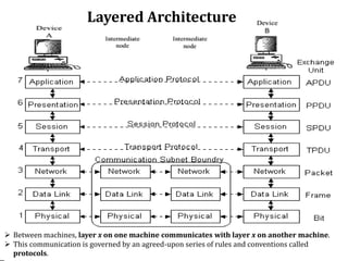
OSI Reference Model
OSI Model
OSI Model
➢ It is a layered framework for the design of network systems
that allows communication between all types of computer
systems.
➢ It consists of seven separate but related layers.
➢ Each layer defines a part of the process of moving
information across a network.
➢ An OSI model provides a solid basis for understanding data
communications.
OSI Model
7 Layers of OSI Model
OSI Model
Layered Architecture
➢ The layers involved when a message is sent from
device A to device B.
➢ As the message travels from A to B, it may pass through many
intermediate nodes.
➢ These intermediate nodes usually involve only the first three
layers of the OSI model.
➢ Each layer performs unique and specific task and it offers
services to the layer above it.
➢ For example, Layer 3 uses the services provided by layer 2
and provides services for layer 4.
OSI Model
Layered Architecture
OSI Model
➢ Between machines, layer x on one machine communicates with layer x on another machine.
➢ This communication is governed by an agreed-upon series of rules and conventions called
protocols.
Peer-to-Peer processes
➢ The processes on each machine that communicate at a given
layer are called peer-to-peer processes.
➢ At the physical layer, communication is direct: Device A
sends a stream of bits to device B (through intermediate
nodes).
➢ At higher layers each layer in the sending machines adds its
own information to the message it receives from the layer
just above it and passes the whole package to the layer just
below it.
OSI Model
➢ The information added by each layer is in the form of headers
or trailers.
➢ At layer 1 the entire package is converted to a form that can be
transferred to the receiving machine.
➢ At the receiving machine, the message is unwrapped layer
by layer, with each process receiving and removing the data
meant for it.
➢ For example, layer 2 removes the data meant for it, then
passes the rest to layer 3.
➢ Layer 3 then removes the data meant for it and passes the rest
to layer 4, and so on.
OSI Model
Peer-to-Peer processes
Interfaces Between Layers
➢ An interface defines the operations and services offered by
lower layer to the upper layer.
➢ This is an interface between each pair of adjacent layers.
➢ The passing of the data and network information down
through the layers of the sending device and receiving device
is made possible by an interface between each pair of adjacent
layers.
OSI Model
Data Encapsulation
➢ The outgoing information will travel down through the layers
to the lowest layer.
➢ While moving down on the source machine, it acquires all the
control information which is required to reach the destination
machine.
➢ The control information is in the form of Headers and Trailer
which surrounds the data received from the layer above.
➢ This process of adding headers and trailers to the data is called
as data encapsulation.
OSI Model
➢ The headers and trailers contain control information.
➢ The headers and trailers form the envelope which carries the
message to the desired destination.
OSI Model
Data Encapsulation
➢ D7 means the data unit at layer 7, D6 means the data unit at
layer 6, and so on.
➢ The process starts at layer 7 (the application layer), then moves
from layer to layer in descending, sequential order.
➢ At each layer, a header, or possibly a trailer, can be added to
the data unit.
➢ Commonly, the trailer is added only at layer 2.
➢ When the formatted data unit passes through the physical layer
(layer 1), it is changed into an electromagnetic signal and
transported along a physical link.
OSI Model
Data Encapsulation
Encapsulation example: E-mail
OSI Model
1. Physical Layer
➢ It co-ordinates the functions required to transmit bit stream
over physical medium.
➢ Provides physical interface for transmission of information.
➢ Defines rules by which bits are passed from one system to
another on a physical communication medium.
➢ Covers all - mechanical, electrical, functional and
procedural - aspects for physical communication.
OSI Model
1. Physical Layer
OSI Model
The physical layer is responsible for the movement of individual
bits from one hop (node) to the next.
Functions
➢ Physical characteristics of interfaces and medium.
✓ It also defines the type of transmission medium.
➢ Representation of bits.
✓ sequence of 0s or 1s
➢ Data rate.
➢ Synchronization of bits.
✓ Sender and Receiver must be synchronized
➢ Physical topology
✓ Mesh, Ring, Star, etc.
➢ Transmission mode.
✓ Simplex, Half duplex, Duplex
OSI Model
1. Physical Layer
OSI Model
➢ What are the Physical Layer components on my computer?
➢ NIC
✓Network Interface Card
✓Has a unique 12 character Hexadecimal number permanently burned into
it at the manufacturer.
✓The number is the MAC Address/Physical address of a computer
➢ Cabling
✓Twister Pair
✓Fiber Optic
✓Coax Cable
2. Data Link Layer
OSI Model
➢ Data link layer attempts to provide reliable communication
over the physical layer interface.
➢ Breaks the outgoing data into frames and re-assemble the
received frames.
➢ Create and detect frame boundaries.
➢ Handle errors by implementing an acknowledgement and
retransmission scheme.
➢ Implement flow control.
2. Data Link Layer
OSI Model
The data link layer is responsible for moving frames from
one hop (node) to the next.
Data Link Layer Functions
➢ Framing- divides the stream of bits into manageable data units called
frames
➢ Physical addressing- adds a header to the frame to define the sender and/or
receiver of the frame.
➢ Flow control- imposes a flow control mechanism to avoid overwhelming the
receiver.
➢ Error control- adds mechanisms to detect and retransmit damaged or lost
frames.
➢ Access control- determine which device has control over the link at any given
time.
➢ Frame sequencing- transmits/receives frames sequentially.
➢ Frame acknowledgment- provides/expects frame acknowledgments.
➢ Link establishment and termination- establishes and terminates the
logical link between two nodes.
OSI Model
Data Link Layer –Sub Layers
➢ DLL is divided into two Sub-Layers
✓ LLC Sub Layer
✓ MAC Sub Layer
OSI Model
a) Logical Link Control Sub Layer
➢ It is upper portion of the Data Link layer.
➢ Performs Flow control and management of connection errors.
➢ LLC supports three types of connections:
1. Unacknowledged connectionless service:
✓ does not perform reliability checks or maintain a connection, very fast,
most commonly used
2. Connection oriented service:
✓ once the connection is established, blocks of data can be transferred
between nodes until one of the node terminates the connection.
3. Acknowledged connectionless service:
✓ provides a mechanism through which individual frames can be
acknowledged.
OSI Model
b) Media Access Control Sub Layer
➢ This sub layer contains methods to regulate the timing of data
signals and eliminate collisions.
➢ The MAC sub layer determines where one frame of data ends
and the next one starts - frame synchronization.
➢ There are four means of frame synchronization:
1. Time based,
2. Character counting,
3. Byte stuffing and
4. Bit stuffing.
OSI Model
3. Network Layer
OSI Model
➢ It is responsible for source to destination delivery of individual
packets across multiple networks.
➢ Defines the most optimum path the packet should take from
the source to the destination
➢ Defines logical addressing so that any endpoint can be
identified.
➢ Handles congestion in the network.
➢ Facilitates interconnection between heterogeneous networks
(Internetworking).
➢ The network layer also defines how to fragment a packet into
smaller packets to accommodate different media.
3. Network Layer
OSI Model
The network layer is responsible for the delivery of individual
packets from the source host to the destination host.
Functions of Network Layer
OSI Model
1. Logical addressing
2. Routing.
3. Congestion control
4. Accounting and billing
5. Address transformation
6. Error free delivery of packet (Source – to – destination)
4. Transport Layer
OSI Model
➢ Purpose of this layer is to provide a reliable mechanism for
the exchange of data between two processes in different
computers.
➢ Ensures that the data units are delivered error free.
➢ Ensures that data units are delivered in sequence.
➢ Ensures that there is no loss or duplication of data units.
➢ Provides connectionless or connection oriented service.
4.Transport Layer
OSI Model
The transport layer is responsible for the delivery of a
message from one process to another.
Functions Transport Layer
OSI Model
1. Connection control
2. Service point addressing
3. Segmentation and reassembly
4. Flow control: Flow control is performed end to end
5. Error control
5. Session Layer
OSI Model
➢ Session layer provides mechanism for controlling the
dialogue between the two end systems.
➢ It defines how to start, control and end conversations (called
sessions) between applications.
➢ This layer requests for a logical connection to be established
on an end-user’s request.
➢ Any necessary log-on or password validation is also handled
by this layer.
1. Dialog control
2. Synchronization, session and sub session
3. Session closure
OSI Model
Functions of Session Layer
➢ Presentation layer defines the format in which the data is to be
exchanged between the two communicating entities.
➢ Its function includes
✓ Translation: presentation layer is responsible for converting various
formats into required format of the recipient.
✓ Encryption: Data encryption and decryption is done by presentation
layer for security.
✓ Compression and Decompression: data to be transform compressed
while sending and decompress while receiving for reducing time of
transmission.
OSI Model
6. Presentation Layer
➢ Application layer interacts with application programs and is
the highest level of OSI model.
➢ Application layer contains management functions to support
distributed applications.
➢ Examples of application layer are applications such as
✓ file transfer,
✓ electronic mail,
✓ remote login etc.
OSI Model
7. Application Layer
1. Network virtual terminal
2. File transfer access and management
3. Mail services and directory services
OSI Model
Functions of Application laye
Horizontal Communication
➢ The horizontal communication is the Logical connection
between the layers.
➢ There is no direct communication between the
corresponding layers.
➢ Information included in each protocol header by the
transmitting system is a message that will be carried to the
same protocol in the destination system.
➢ For two computers to communicate over a n/w, the protocol
used at each layer of the OSI model in the transmitting system
must be duplicated at the receiving system.
OSI Model
When the packet
reaches at its
destination, the
process by which the
headers are applied
at the source is
reversed in receiver
to get information.
OSI Model
Horizontal Communication
➢ The header information also enables each layer to
communicate with the layer above & below it.
• E.g. The n/w layer will communicate with the data link layer & transport
layer.
➢ This is an interlayer communication.
➢ When a system receives a packet & passes it up through various
layers the data link layer protocol header includes a field which
specifies the name of n/w layer protocol to be used to process
the packet.
OSI Model
Vertical Communication
The n/w layer protocol
header will specify the
name of transport layer
protocol to be used to
process the packet.
OSI Model
Vertical Communication
➢ Connection-oriented communication includes the steps of setting
up a call from one computer to another, transmitting/receiving
data, and then releasing the call, just like a voice phone call.
➢ However, the network connecting the computers is a packet
switched network.
➢ Connection-oriented communication is done in one of two ways
over a packet switched network: with and without virtual
circuits.
➢ We can resend the message in connection oriented service if there
is an error at the receivers end.
➢ Example of connection oriented is TCP (Transmission Control
Protocol) protocol.
OSI Model
Connection Oriented Services
➢ Connectionless communication is just packet switching
where no call establishment and release occur.
➢ A message is broken into packets, and each packet is
transferred separately.
➢ Moreover, the packets can travel different route to the
destination since there is no connection.
➢ Connectionless service is typically provided by the UDP (User
Datagram Protocol).
➢ The packets transferred using UDP are also called datagrams.
OSI Model
Connectionless Services
Protocols - Layer 7 HTTP, FTP, SMTP, POP, DNS, Telnet
Protocols - Layer 6 Graphics: TIFF, JPEG, GIF Text: ASCII, EBCDIC,
Unicode, Encrypted Audio: Midi, MPEG, WAV, MP3
Video: Quicktime, AVI
Protocols - Layer 5 NFS - Network File System, RPC - Remote Procedure
Call, ASP - Appletalk Session Protocol
Protocols - Layer 4 Connection Oriented (TCP), Connectionless (UDP)
Protocols - Layer 3 Routing (IP)
Protocols - Layer 2 MAC - Media Access Control, LLC - Logical Link
Control
Protocols - Layer 1 Organizations: IEE, TIA/ETA, ANSI, etc. Cable
(ie. RJ45)
OSI Model
Protocols
OSI Model
Devices
Devices - Layer 7 Hosts, PC, Servers, Mobile Phones
Devices - Layer 3 Routers
Devices - Layer 2 Bridges, Switches, NIC (Layers 1 & 2)
Devices - Layer 1 Hubs, NIC (Layers 1 & 2)
Media: Coax, Fiber, Twisted Pair, Wireless
OSI Model
Summery
Remembering the 7 Layers
7 - Application All Away
6 - Presentation People Pizza
5 - Session Seem Sausage
4 - Transport To Throw
3 - Network Need Not
2 - Data Link Data Do
1 - Physical Processing Please
OSI Reference Model.pdf

OSI Reference Model.pdf

  • 1.
  • 2.
    OSI Model ➢ Itis a layered framework for the design of network systems that allows communication between all types of computer systems. ➢ It consists of seven separate but related layers. ➢ Each layer defines a part of the process of moving information across a network. ➢ An OSI model provides a solid basis for understanding data communications. OSI Model
  • 3.
    7 Layers ofOSI Model OSI Model
  • 4.
    Layered Architecture ➢ Thelayers involved when a message is sent from device A to device B. ➢ As the message travels from A to B, it may pass through many intermediate nodes. ➢ These intermediate nodes usually involve only the first three layers of the OSI model. ➢ Each layer performs unique and specific task and it offers services to the layer above it. ➢ For example, Layer 3 uses the services provided by layer 2 and provides services for layer 4. OSI Model
  • 5.
    Layered Architecture OSI Model ➢Between machines, layer x on one machine communicates with layer x on another machine. ➢ This communication is governed by an agreed-upon series of rules and conventions called protocols.
  • 6.
    Peer-to-Peer processes ➢ Theprocesses on each machine that communicate at a given layer are called peer-to-peer processes. ➢ At the physical layer, communication is direct: Device A sends a stream of bits to device B (through intermediate nodes). ➢ At higher layers each layer in the sending machines adds its own information to the message it receives from the layer just above it and passes the whole package to the layer just below it. OSI Model
  • 7.
    ➢ The informationadded by each layer is in the form of headers or trailers. ➢ At layer 1 the entire package is converted to a form that can be transferred to the receiving machine. ➢ At the receiving machine, the message is unwrapped layer by layer, with each process receiving and removing the data meant for it. ➢ For example, layer 2 removes the data meant for it, then passes the rest to layer 3. ➢ Layer 3 then removes the data meant for it and passes the rest to layer 4, and so on. OSI Model Peer-to-Peer processes
  • 8.
    Interfaces Between Layers ➢An interface defines the operations and services offered by lower layer to the upper layer. ➢ This is an interface between each pair of adjacent layers. ➢ The passing of the data and network information down through the layers of the sending device and receiving device is made possible by an interface between each pair of adjacent layers. OSI Model
  • 10.
    Data Encapsulation ➢ Theoutgoing information will travel down through the layers to the lowest layer. ➢ While moving down on the source machine, it acquires all the control information which is required to reach the destination machine. ➢ The control information is in the form of Headers and Trailer which surrounds the data received from the layer above. ➢ This process of adding headers and trailers to the data is called as data encapsulation. OSI Model
  • 11.
    ➢ The headersand trailers contain control information. ➢ The headers and trailers form the envelope which carries the message to the desired destination. OSI Model Data Encapsulation
  • 12.
    ➢ D7 meansthe data unit at layer 7, D6 means the data unit at layer 6, and so on. ➢ The process starts at layer 7 (the application layer), then moves from layer to layer in descending, sequential order. ➢ At each layer, a header, or possibly a trailer, can be added to the data unit. ➢ Commonly, the trailer is added only at layer 2. ➢ When the formatted data unit passes through the physical layer (layer 1), it is changed into an electromagnetic signal and transported along a physical link. OSI Model Data Encapsulation
  • 13.
  • 14.
    1. Physical Layer ➢It co-ordinates the functions required to transmit bit stream over physical medium. ➢ Provides physical interface for transmission of information. ➢ Defines rules by which bits are passed from one system to another on a physical communication medium. ➢ Covers all - mechanical, electrical, functional and procedural - aspects for physical communication. OSI Model
  • 15.
    1. Physical Layer OSIModel The physical layer is responsible for the movement of individual bits from one hop (node) to the next.
  • 16.
    Functions ➢ Physical characteristicsof interfaces and medium. ✓ It also defines the type of transmission medium. ➢ Representation of bits. ✓ sequence of 0s or 1s ➢ Data rate. ➢ Synchronization of bits. ✓ Sender and Receiver must be synchronized ➢ Physical topology ✓ Mesh, Ring, Star, etc. ➢ Transmission mode. ✓ Simplex, Half duplex, Duplex OSI Model
  • 17.
    1. Physical Layer OSIModel ➢ What are the Physical Layer components on my computer? ➢ NIC ✓Network Interface Card ✓Has a unique 12 character Hexadecimal number permanently burned into it at the manufacturer. ✓The number is the MAC Address/Physical address of a computer ➢ Cabling ✓Twister Pair ✓Fiber Optic ✓Coax Cable
  • 18.
    2. Data LinkLayer OSI Model ➢ Data link layer attempts to provide reliable communication over the physical layer interface. ➢ Breaks the outgoing data into frames and re-assemble the received frames. ➢ Create and detect frame boundaries. ➢ Handle errors by implementing an acknowledgement and retransmission scheme. ➢ Implement flow control.
  • 19.
    2. Data LinkLayer OSI Model The data link layer is responsible for moving frames from one hop (node) to the next.
  • 20.
    Data Link LayerFunctions ➢ Framing- divides the stream of bits into manageable data units called frames ➢ Physical addressing- adds a header to the frame to define the sender and/or receiver of the frame. ➢ Flow control- imposes a flow control mechanism to avoid overwhelming the receiver. ➢ Error control- adds mechanisms to detect and retransmit damaged or lost frames. ➢ Access control- determine which device has control over the link at any given time. ➢ Frame sequencing- transmits/receives frames sequentially. ➢ Frame acknowledgment- provides/expects frame acknowledgments. ➢ Link establishment and termination- establishes and terminates the logical link between two nodes. OSI Model
  • 21.
    Data Link Layer–Sub Layers ➢ DLL is divided into two Sub-Layers ✓ LLC Sub Layer ✓ MAC Sub Layer OSI Model
  • 22.
    a) Logical LinkControl Sub Layer ➢ It is upper portion of the Data Link layer. ➢ Performs Flow control and management of connection errors. ➢ LLC supports three types of connections: 1. Unacknowledged connectionless service: ✓ does not perform reliability checks or maintain a connection, very fast, most commonly used 2. Connection oriented service: ✓ once the connection is established, blocks of data can be transferred between nodes until one of the node terminates the connection. 3. Acknowledged connectionless service: ✓ provides a mechanism through which individual frames can be acknowledged. OSI Model
  • 23.
    b) Media AccessControl Sub Layer ➢ This sub layer contains methods to regulate the timing of data signals and eliminate collisions. ➢ The MAC sub layer determines where one frame of data ends and the next one starts - frame synchronization. ➢ There are four means of frame synchronization: 1. Time based, 2. Character counting, 3. Byte stuffing and 4. Bit stuffing. OSI Model
  • 24.
    3. Network Layer OSIModel ➢ It is responsible for source to destination delivery of individual packets across multiple networks. ➢ Defines the most optimum path the packet should take from the source to the destination ➢ Defines logical addressing so that any endpoint can be identified. ➢ Handles congestion in the network. ➢ Facilitates interconnection between heterogeneous networks (Internetworking). ➢ The network layer also defines how to fragment a packet into smaller packets to accommodate different media.
  • 25.
    3. Network Layer OSIModel The network layer is responsible for the delivery of individual packets from the source host to the destination host.
  • 26.
    Functions of NetworkLayer OSI Model 1. Logical addressing 2. Routing. 3. Congestion control 4. Accounting and billing 5. Address transformation 6. Error free delivery of packet (Source – to – destination)
  • 27.
    4. Transport Layer OSIModel ➢ Purpose of this layer is to provide a reliable mechanism for the exchange of data between two processes in different computers. ➢ Ensures that the data units are delivered error free. ➢ Ensures that data units are delivered in sequence. ➢ Ensures that there is no loss or duplication of data units. ➢ Provides connectionless or connection oriented service.
  • 28.
    4.Transport Layer OSI Model Thetransport layer is responsible for the delivery of a message from one process to another.
  • 29.
    Functions Transport Layer OSIModel 1. Connection control 2. Service point addressing 3. Segmentation and reassembly 4. Flow control: Flow control is performed end to end 5. Error control
  • 30.
    5. Session Layer OSIModel ➢ Session layer provides mechanism for controlling the dialogue between the two end systems. ➢ It defines how to start, control and end conversations (called sessions) between applications. ➢ This layer requests for a logical connection to be established on an end-user’s request. ➢ Any necessary log-on or password validation is also handled by this layer.
  • 31.
    1. Dialog control 2.Synchronization, session and sub session 3. Session closure OSI Model Functions of Session Layer
  • 32.
    ➢ Presentation layerdefines the format in which the data is to be exchanged between the two communicating entities. ➢ Its function includes ✓ Translation: presentation layer is responsible for converting various formats into required format of the recipient. ✓ Encryption: Data encryption and decryption is done by presentation layer for security. ✓ Compression and Decompression: data to be transform compressed while sending and decompress while receiving for reducing time of transmission. OSI Model 6. Presentation Layer
  • 33.
    ➢ Application layerinteracts with application programs and is the highest level of OSI model. ➢ Application layer contains management functions to support distributed applications. ➢ Examples of application layer are applications such as ✓ file transfer, ✓ electronic mail, ✓ remote login etc. OSI Model 7. Application Layer
  • 34.
    1. Network virtualterminal 2. File transfer access and management 3. Mail services and directory services OSI Model Functions of Application laye
  • 35.
    Horizontal Communication ➢ Thehorizontal communication is the Logical connection between the layers. ➢ There is no direct communication between the corresponding layers. ➢ Information included in each protocol header by the transmitting system is a message that will be carried to the same protocol in the destination system. ➢ For two computers to communicate over a n/w, the protocol used at each layer of the OSI model in the transmitting system must be duplicated at the receiving system. OSI Model
  • 36.
    When the packet reachesat its destination, the process by which the headers are applied at the source is reversed in receiver to get information. OSI Model Horizontal Communication
  • 37.
    ➢ The headerinformation also enables each layer to communicate with the layer above & below it. • E.g. The n/w layer will communicate with the data link layer & transport layer. ➢ This is an interlayer communication. ➢ When a system receives a packet & passes it up through various layers the data link layer protocol header includes a field which specifies the name of n/w layer protocol to be used to process the packet. OSI Model Vertical Communication
  • 38.
    The n/w layerprotocol header will specify the name of transport layer protocol to be used to process the packet. OSI Model Vertical Communication
  • 39.
    ➢ Connection-oriented communicationincludes the steps of setting up a call from one computer to another, transmitting/receiving data, and then releasing the call, just like a voice phone call. ➢ However, the network connecting the computers is a packet switched network. ➢ Connection-oriented communication is done in one of two ways over a packet switched network: with and without virtual circuits. ➢ We can resend the message in connection oriented service if there is an error at the receivers end. ➢ Example of connection oriented is TCP (Transmission Control Protocol) protocol. OSI Model Connection Oriented Services
  • 40.
    ➢ Connectionless communicationis just packet switching where no call establishment and release occur. ➢ A message is broken into packets, and each packet is transferred separately. ➢ Moreover, the packets can travel different route to the destination since there is no connection. ➢ Connectionless service is typically provided by the UDP (User Datagram Protocol). ➢ The packets transferred using UDP are also called datagrams. OSI Model Connectionless Services
  • 41.
    Protocols - Layer7 HTTP, FTP, SMTP, POP, DNS, Telnet Protocols - Layer 6 Graphics: TIFF, JPEG, GIF Text: ASCII, EBCDIC, Unicode, Encrypted Audio: Midi, MPEG, WAV, MP3 Video: Quicktime, AVI Protocols - Layer 5 NFS - Network File System, RPC - Remote Procedure Call, ASP - Appletalk Session Protocol Protocols - Layer 4 Connection Oriented (TCP), Connectionless (UDP) Protocols - Layer 3 Routing (IP) Protocols - Layer 2 MAC - Media Access Control, LLC - Logical Link Control Protocols - Layer 1 Organizations: IEE, TIA/ETA, ANSI, etc. Cable (ie. RJ45) OSI Model Protocols
  • 42.
    OSI Model Devices Devices -Layer 7 Hosts, PC, Servers, Mobile Phones Devices - Layer 3 Routers Devices - Layer 2 Bridges, Switches, NIC (Layers 1 & 2) Devices - Layer 1 Hubs, NIC (Layers 1 & 2) Media: Coax, Fiber, Twisted Pair, Wireless
  • 43.
  • 44.
    Remembering the 7Layers 7 - Application All Away 6 - Presentation People Pizza 5 - Session Seem Sausage 4 - Transport To Throw 3 - Network Need Not 2 - Data Link Data Do 1 - Physical Processing Please