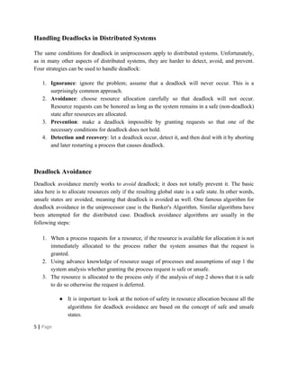
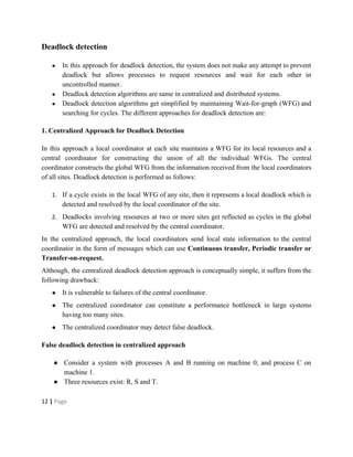
Deadlocks occur when processes are waiting for resources held by other processes, resulting in a circular wait. Four conditions must be met: mutual exclusion, hold and wait, no preemption, and circular wait. Deadlocks can be handled through avoidance, prevention, or detection and recovery. Avoidance algorithms allocate resources only if it ensures the system remains in a safe state where deadlocks cannot occur. Prevention methods make deadlocks impossible by ensuring at least one condition is never satisfied, such as through collective or ordered resource requests. Detection finds existing deadlocks by analyzing resource allocation graphs or wait-for graphs to detect cycles.
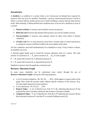
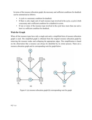
Gurgaon ✡️9711147426✨Call In girls Gurgaon Sector 51 escort service
Deadlock in Distributed Systems
1. IIT, University of Dhaka
Deadlock in
Distributed Systems
Course Name: Distributed Systems
Course Code: CSE 601
Submitted To
Dr. Kazi Muheymin-Us-Sakib
Professor, IIT, University of Dhaka
Submitted By
Pritom Saha Akash
BSSE 0604
11-7-2016
2. Introduction
A deadlock is a condition in a system where a set of processes (or threads) have requests for
resources that can never be satisfied. Essentially, a process cannot proceed because it needs to
obtain a resource held by another process but it itself is holding a resource that the other process
needs. More formally, Coffman defined four conditions have to be met for a deadlock to occur in
a system:
1. Mutual exclusion A resource can be held by at most one process.
2. Hold and wait Processes that already hold resources can wait for another resource.
3. Non-preemption A resource, once granted, cannot be taken away unless it releases
voluntarily.
4. Circular wait Two or more processes must form a circular chain in which each process
is waiting for resource held that is held by the next number of the chain.
All four conditions must hold simultaneously for a deadlock to occur. If any of them is absent,
no deadlock can occur.
A directed graph model used to record the resource allocation state of a system. This state
consists of n processes, P1 … Pn, and m resources, R1 … Rm. In such a graph:
P1 → R1 means that resource R1 is allocated to process P1.
P1 ← R1 means that resource R1 is requested by process P1.
Deadlock is present when the graph has a directed cycle.
Resource Allocation Graph
In some cases, deadlocks can be understood more clearly through the use of
Resource-Allocation Graphs, having the following properties:
● A set of resource categories, {R1, R2, R3, . . ., RN}, which appear as square nodes on the
graph. Dots inside the resource nodes indicate specific instances of the resource. (E.g.
two dots might represent two laser printers.)
● A set of processes, {P1, P2, P3, . . ., PN}
● Request Edges - A set of directed arcs from Pi to Rj, indicating that process Pi has
requested Rj, and is currently waiting for that resource to become available.
● Assignment Edges - A set of directed arcs from Rj to Pi indicating that resource Rj has
been allocated to process Pi, and that Pi is currently holding resource Rj.
1 | Page
3. ● Note that a request edge can be converted into an assignment edge by reversing the
direction of the arc when the request is granted. (However note also that request edges
point to the category box, whereas assignment edges emanate from a particular instance
dot within the box.)
● For example:
Figure 1: Resource allocation graph
● If a resource-allocation graph contains no cycles, then the system is not deadlocked.
(When looking for cycles, remember that these are directed graphs.) See the example in
Figure 2 above.
● If a resource-allocation graph does contain cycles AND each resource category contains
only a single instance, then a deadlock exists.
● If a resource category contains more than one instance, then the presence of a cycle in the
resource-allocation graph indicates the possibility of a deadlock, but does not guarantee
one. In this case, a sufficient condition for deadlock. Consider, for example, Figures 3
and 4 below:
2 | Page
4. Figure 2: Resource allocation graph with a cycle but no deadlock
Figure 3 - Resource allocation graph with a knot with deadlock
[Knot: subgraph such that starting from any node in the subgraph it is impossible to leave the
knot following the edges of the graph.]
3 | Page
5. In terms of the resource allocation graph, the necessary and sufficient conditions for deadlock
can be summarized as follows:
▪ A cycle is a necessary condition for deadlock
▪ If there is only single unit of each resource type involved in the cycle, a cycle is both
a necessary and a sufficient condition for a deadlock to exists.
▪ If one or more of the resource type involved in the cycle have more than one unit a
knot is a sufficient condition for deadlock.
Wait-for Graph
When all the resource types have only a single unit each, a simplified form of resource allocation
graph is used. The simplified graph is obtained from the original resource allocation graph by
removing the resource nodes and collapsing the appropriate edges. This simplification is based
on the observation that a resource can always be identified by its owner process. There are a
resource allocation graph and its corresponding wait-for graph below:
Figure 4: (a) resource allocation graph (b) corresponding wait for graph
4 | Page
6. Handling Deadlocks in Distributed Systems
The same conditions for deadlock in uniprocessors apply to distributed systems. Unfortunately,
as in many other aspects of distributed systems, they are harder to detect, avoid, and prevent.
Four strategies can be used to handle deadlock:
1. Ignorance: ignore the problem; assume that a deadlock will never occur. This is a
surprisingly common approach.
2. Avoidance: choose resource allocation carefully so that deadlock will not occur.
Resource requests can be honored as long as the system remains in a safe (non-deadlock)
state after resources are allocated.
3. Prevention: make a deadlock impossible by granting requests so that one of the
necessary conditions for deadlock does not hold.
4. Detection and recovery: let a deadlock occur, detect it, and then deal with it by aborting
and later restarting a process that causes deadlock.
Deadlock Avoidance
Deadlock avoidance merely works to avoid deadlock; it does not totally prevent it. The basic
idea here is to allocate resources only if the resulting global state is a safe state. In other words,
unsafe states are avoided, meaning that deadlock is avoided as well. One famous algorithm for
deadlock avoidance in the uniprocessor case is the Banker's Algorithm. Similar algorithms have
been attempted for the distributed case. Deadlock avoidance algorithms are usually in the
following steps:
1. When a process requests for a resource, if the resource is available for allocation it is not
immediately allocated to the process rather the system assumes that the request is
granted.
2. Using advance knowledge of resource usage of processes and assumptions of step 1 the
system analysis whether granting the process request is safe or unsafe.
3. The resource is allocated to the process only if the analysis of step 2 shows that it is safe
to do so otherwise the request is deferred.
● It is important to look at the notion of safety in resource allocation because all the
algorithms for deadlock avoidance are based on the concept of safe and unsafe
states.
5 | Page
7. ● A system is said to be in safe state if it is not in a deadlock state and there exists
some ordering of the process in which the requests are granted to run all of them
to completion.
● Any ordering of the process that can guarantee the completion of all the processes
is called safe sequence.
● The formation of safe sequence should satisfy the condition that for any process
Pi in a safe sequence, the resource that Pi can still request and can be satisfied by
currently available resources plus the resources held by all processes lying before
Pi in the safe sequence.
● This condition guarantees that the process Pi can be run to completion if the
resource that Pi needs are not immediately available and Pi can wait until all the
processes in the sequence lying before Pi have finished. When they have finished
Pi can obtain all its needed resource and run to completion.
● A system is said to be unsafe if no safe sequence exists for that state.
● For example: Assume a system having 8 units of a particular resource type for
which three processes P1, P2 and P3 are competing and the maximum units of the
resource required by them are 4, 5, and 6 respectively.
● Each of the three resources is holding 2 units of the resource therefore in the
current state of the system 2 units of resource are free. The aim is to find whether
stat in fig(a) is safe or unsafe. The figure shows that the state is safe because
sequence of allocations to allow process completion exists and the safe sequences
are (P1, P2, P3) and (P1, P3, P2).
● In fig(a) the scheduler could simple run P1 until it asked for and got two more
units of the resource that are currently free leading to state of fig(b). When P1
completes and releases the resource held by it the state in fig(c) is achieved. Then
the scheduler chooses to run P2 which leads to the next state of fig (d). When P2
completes and releases resources held by it the system enters the state of fig(e).
P3 can now run to completion with the available resources.
6 | Page
8. Figure 5: Demonstrate that the state (a) is a safe state and has two safe sequence
● The initial state of fig(a) is safe state because the system can avoid deadlock by
careful scheduling. If resource allocation is not done carefully the system can
move from a safe state to unsafe state.
● Deadlock avoidance algorithm basically perform resource allocation is such a
manner that ensures the system will always remain in safe state.
● Since initial state is always safe state, when a process requests a resource that is
available, the system checks if allocation causes the shift from safe to unsafe
state. If no, then the request is granted or else it is deferred.
7 | Page
9. Deadlock Prevention
This approach is based on the idea of designing the system in such a way that the deadlock
become impossible. It differs from avoidance and detection in that no runtime testing of potential
allocations need be performed. We saw that mutual exclusion, hold and wait, no-preemption and
circular wait are the four necessary conditions for deadlock to occur in a system. Therefore, if we
can somehow ensure that at least one of these conditions is never satisfied, deadlock will be
impossible. Based on this idea, there are three important deadlock-prevention methods-
collective requests, ordered requests and preemption.
Collective Requests
These methods deny the hold and wait condition by ensuring that whenever a process requests a
resource it does not hold any other resource. Various resource allocation policies can be used.
For instance, in order to prevent the Hold & Wait condition from happening one of the following
resource allocation policies may be used:
1. A process must request all of its resources before it begins execution. If all the needed
resources are available, they are allocated to the process so that the process can run to
completion. If one or more of the requested resources are not available, none will be
allocated and the process would just wait.
2. Instead of requiring all the resources before it begins execution, a process may request
resources during its execution if it obeys the rule that it requests resources only when it
holds no other resources. If the process is holding some resources, it can adhere to the
rule by first releasing all of them and re-requesting all the necessary resources.
The second policy has the following advantages over the first one:
1. In practice, many process do not know how many resources they will need until they
have started running. For such cases, the second approach is more useful.
2. A long process may require some resources only towards the end of its execution. In the
first policy, the process will unnecessarily hold these resources for the entire duration of
its execution. In the second policy, the process can request for those resources only when
it needs them.
8 | Page
10. The collective requests method is simple and effective but has the following problems:
● This degrades resource utilization.
● It also leads to starvation for those processes with large resource needs.
● The method also rises an accounting question. When a process holds resources for
extended periods during which they are not needed, it is not clear who should pay the
charge for the idled resources.
Ordered Requests
In this method circular-wait is denied such that each resource type is assigned a unique global
number to impose total ordering of all resource types. Now a resource allocation policy is used
according to which a process can only request resources in classes higher than the classes it
currently holds. That is, if a process holds a resource type whose number is i, it may request a
resource type having a number j only if j>i.
Note that this algorithm does not require that a process must acquire all its resources in strictly
increasing sequence. For instance, a process holding two resources having numbers 3 and 7 may
release the resource having number 7 before requesting the resource having number 5. This is all
allowed because when the process requests for the resource having number 5, it is not holding
any resource having number larger than 5.
This method may face the following problems:
● The natural ordering is not always same for all jobs. Therefore, a job that matches the
decided ordering can be expected to use the resources efficiently but the others would
waste the resources.
● Once the ordering has been decided, it will stay for a long time because the ordering is
coded into programs. Reordering will require reprogramming of several jobs. However,
reordering may become inevitable when new resources are added.
Despite these difficulties, the method of ordered requests is one of the most efficient for handling
deadlocks.
Preemption
A preemptable resource is one whose state can easily be saved and restored later. Such a resource
can be temporarily taken away from the process to which it is currently allocated without causing
9 | Page
11. any harm to the computation performed so far by the process. The CPU register and main
memory are the examples of preemptable resources. If the resources are preemptable, deadlocks
can be prevented by using one of the following resource allocation policy that deny the
no-preemption condition:
1. When a process requests for a resource that is not currently available, all the resources
held by the process are taken away (preempted) from it and the process is blocked. The
process is unblocked when the resource requested by it and the resources preempted
from it become available and can be allocated to it.
2. When a process requests for a resource that is not currently available, the system checks
if the requested resource is currently held a process that is blocked, waiting for some
other resources. If so, the requested resource is taken away(preempted) from the waiting
process and given to the requesting process. Otherwise, the requesting process is blocked
and waits for the resource to become available. Some of the resources that the process is
already holding may be taken away from it while it is blocked, waiting for the requested
resource. The process is unblocked when the requested resource and any other resources
are preempted from it become available.
In the transaction based deadlock prevention method, each transaction is assigned a unique
priority number by the system and when two or more transaction compete for the same resource,
their priority numbers are used to break the tie. For example, Lamport’s algorithm may be used
to generate a system wide globally unique time stamp when it is created. A transaction
timestamp may be used as its priority number; a transaction having a lower value of timestamp
may have higher priority because it is older.
Rosencrantz et al. proposed the following deadlock prevention schemes based on the above
ideas:
Wait-Die Scheme
In this scheme, if a transaction requests to lock a resource (data item), which is already held with
a conflicting lock by another transaction, then one of the two possibilities may occur −
● If TS(Ti) < TS(Tj) − that is Ti, which is requesting a conflicting lock, is older than Tj −
then Ti is allowed to wait until the data-item is available.
● If TS(Ti) > TS(Tj) − that is Ti is younger than Tj − then Ti dies. Ti is restarted later with a
random delay but with the same timestamp.
10 | Page
12. This scheme allows the older transaction to wait but kills the younger one.
Figure 6: Wait-Die Scheme
Wound- Wait Scheme
In this scheme, if a transaction requests to lock a resource (data item), which is already held with
conflicting lock by some other transaction, one of the two possibilities may occur:
● If TS(Ti) < TS(Tj), then Ti forces Tj to be rolled back − that is Ti wounds Tj. Tj is restarted
later with a random delay but with the same timestamp.
● If TS(Ti) > TS(Tj), then Ti is forced to wait until the resource is available.
This scheme, allows the younger transaction to wait; but when an older transaction requests an
item held by a younger one, the older transaction forces the younger one to abort and release the
item.
Figure 7: Wound-Wait Scheme
In both the cases, the transaction that enters the system at a later stage is aborted.
11 | Page
13. Deadlock detection
● In this approach for deadlock detection, the system does not make any attempt to prevent
deadlock but allows processes to request resources and wait for each other in
uncontrolled manner.
● Deadlock detection algorithms are same in centralized and distributed systems.
● Deadlock detection algorithms get simplified by maintaining Wait-for-graph (WFG) and
searching for cycles. The different approaches for deadlock detection are:
1. Centralized Approach for Deadlock Detection
In this approach a local coordinator at each site maintains a WFG for its local resources and a
central coordinator for constructing the union of all the individual WFGs. The central
coordinator constructs the global WFG from the information received from the local coordinators
of all sites. Deadlock detection is performed as follows:
1. If a cycle exists in the local WFG of any site, then it represents a local deadlock which is
detected and resolved by the local coordinator of the site.
2. Deadlocks involving resources at two or more sites get reflected as cycles in the global
WFG are detected and resolved by the central coordinator.
In the centralized approach, the local coordinators send local state information to the central
coordinator in the form of messages which can use Continuous transfer, Periodic transfer or
Transfer-on-request.
Although, the centralized deadlock detection approach is conceptually simple, it suffers from the
following drawback:
● It is vulnerable to failures of the central coordinator.
● The centralized coordinator can constitute a performance bottleneck in large systems
having too many sites.
● The centralized coordinator may detect false deadlock.
False deadlock detection in centralized approach
● Consider a system with processes A and B running on machine 0, and process C on
machine 1.
● Three resources exist: R, S and T.
12 | Page
14. ● Initially:
▪ A holds S but wants R, which it cannot have because B is using it;
▪ C has T and wants S, too.
▪ The coordinator's view of the world is shown in (c)
▪ This configuration is safe: as soon as B finishes, A can get R and finish, releasing
S for C.
● After a while:
▪ B releases R and asks for T, a perfectly legal and safe swap.
▪ Machine 0 sends a message to the coordinator announcing the release of R,
▪ Machine 1 sends a message to the coordinator announcing the fact that B is now
waiting for its resource, T.
▪ Unfortunately, the message from machine 1 arrives first, leading the coordinator
to construct the graph of (d).
▪ The coordinator incorrectly concludes that a deadlock exists and kills some
process.
Such a situation is called a false deadlock
Figure 8: (a) Initial resource graph for machine 0 (b) Initial resource graph for
machine 1 (c) The coordinator's view of the world. (d) The situation after the delayed
message
Way out using Lamport’s algorithm
● Since the message from machine 1 to the coordinator is triggered by the request from
machine 0, the message from machine 1 to the coordinator will have a later timestamp
than the message from machine 0 to the coordinator.
● When the coordinator gets the message from machine 1 that leads it to suspect deadlock,
send a message to every machine in the system saying: “I just received a message with
13 | Page
15. timestamp T which leads to deadlock. If anyone has a message for me with an earlier
timestamp, please send it immediately.”
● When every machine has replied, positively or negatively, the coordinator will see that
the arc from R to B has vanished, so the system is still safe.
● Although this method eliminates the false deadlock, it requires global time and is
expensive
2. Hierarchical Approach for Deadlock Detection
The hierarchical approach overcomes drawbacks of the centralized approach. This approach uses
a logical hierarchy of deadlock detectors called as controllers. Each controller detects only those
deadlocks that have the sites falling within the range of the hierarchy. Global WFG is distributed
over a number of different controllers in this approach. Each site has its own local controller that
maintains its own local graph. WFG is maintained by a controller use the following rules:
i. Each controller that forms a leaf of the hierarchy tree maintains the local WFG of
a single site.
ii. Each non-leaf controller maintains a WFG that is the union of the WFGs of its
immediate children in the hierarchy tree.
The lowest level controller that finds a cycle in its WFG detects a deadlock ant takes necessary
action to resolve it. WFG that contains a cycle that will never be passed as it is to higher level
controller.
Let A, B, and C be controllers such that C is the lowest common ancestor of A and B. If pi
appears in the local wait-for graphs of controllers A and B, it must also appear in the wait-for
graph of
● controller C,
● every controller on the path from C to A, and
● every controller on the path from C to B.
In other words, if pi and pj are in the wait-for graph of a controller D and there is a path from pi
to pj at any controller, then the edge (pi, pj) must also be in the graph of controller D.
14 | Page
16. In the diagram below, we omit the input and output ports and instead show the state of the
controller.
Figure 9: Hierarchical deadlock detection approach
3. Fully Distributed Approach for Deadlock Detection
In this approach each site shares equal responsibility for deadlock detection. The first algorithm
is based on construction of WFG and second one is a probe-based algorithm.
WFG-Based Distributed Algorithm for Deadlock Detection
In this algorithm each site maintains its own local WFG but for external processes a modified
form of WGF is used. In this an extra node Pex is added to the local WFG of each site and this
node is connected to the WFG of the corresponding site in the following manner:
i. An edge (Pi, Pex) is added if process Pi is waiting for a resource in another site being
held by any process.
ii. An edge (Pex, Pj) is added if Pj is a process of another site that is waiting for a resource
currently being held by a process of this site.
For example, the local site 1 WFG figure-10(a) shows
● process P3 waiting for a resource held by process P2;
15 | Page
17. ● process P2 waiting for a resource held by process P1; and
● process P2 waiting for a resource held by process P4.
Figure 10(a): Local WFG at Site 1 and 2
The local site 2 figure-10(a) WFG shows
• process P1 waiting for a resource held by process P3; and
• process P3 waiting for a resource held by process P4.
These do not show which processes are external to sites 1 or 2
The algorithm expands the local WFGs by adding a node, Pex, to represent the external
dependencies.
In Site 1 of the figure-10(b),
● Edge (P1, Pex) implies that P1 is waiting for a resource at Site 2 that is held by P3.
● Edge (Pex, P3) implies that P3 is a process at Site 2 waiting for a resource that is held by
P2 of site 1.
16 | Page
18. Figure 10(b): Expanded Local WFG at Site 1 and 2
In Site 2 of the figure-10(b),
● Edge (P3, Pex) implies that P3 is waiting for a resource at Site 1.
● Edge (Pex, P1) implies that P1 is a process at Site 1 waiting for a resource that is held by
P3 of site 2.
At this point, site 1 recognizes that it has a cycle in its expanded local WFG that contains Pex.
So it sends a deadlock message to site 2, because one of the known external dependencies of site
1 (P3) is on site 2.
This deadlock message contains not the entire WFG for site 1, but just the path for that part of
the cycle that does not include Pex.
From this, site 2 updates its expanded local WFG as figure-10(c):
17 | Page
19. Figure 10(c): Updated Expanded WFG at Site 2
Advantages of WFG based deadlock detection approach is similar to centralized approach
Disadvantage of this approach is overhead of unnecessary message transfer, Duplication of
deadlock detection jobs.
Probe-Based Distributed Algorithm for Deadlock Detection
This algorithm is also known as Chandy-Misra-Hass algorithm and is considered to be the best
algorithm for detecting global deadlocks in distributed systems. The algorithm allows a process
to request for multiple resources at a time.
1. When a process requests for a resource and fails to get the resource and time out occurs it
generates a special probe message and sends it to the requested resource process.
2. Each probe message contains the following information:
• the id of the process that is blocked (the one that initiates the probe message);
• the id of the process is sending this particular version of the probe message; and
• the id of the process that should receive this probe message.
3. When a process receives a probe message, it checks to see if it is also waiting for
resources.
• If not, it is currently using the needed resource and will eventually finish and
release the resource.
18 | Page
20. • If it is waiting for resources, it passes on the probe message to all processes it
knows to be holding resources it has itself requested. The process first modifies
the probe message, changing the sender and receiver ids.
4. If a process receives a probe message that it recognizes as having initiated, it knows there
is a cycle in the system and thus, deadlock.
The following example is based on the same data used in the WFG- based approach example.
In this case P1 initiates the probe message, so that all the messages shown have P1 as the
initiator. When the probe message is received by process P3, it modifies it and sends it to two
more processes. Eventually, the probe message returns to process P1. Deadlock!
Figure 11: Example illustrating the CMH distributed deadlock detection algorithm
The advantages of this algorithm include the following:
● It is easy to implement.
● Each probe message is of fixed length.
● There is very little computation.
● There is very little overhead.
● There is no need to construct a graph, nor to pass graph information to other sites.
● This algorithm does not find false (phantom) deadlock.
19 | Page
21. ● There is no need for special data structures.
Recovery from Deadlock
Once deadlock has been detected within a distributed system, there must be a way to recover
from it (or why bother to detect it in the first place?).
We need to rollback or abort one or more processes. (In a database system, a partial rollback may
work.) Hopefully, the same situation will not re-occur.
Possible methods for recovery:
• Operator intervention: At one time, this was a feasible alternative for uniprocessor
systems. However, it has little value for today's distributed systems.
• Termination of Process(es): Some victim process (or set of processes) is chosen for
termination from the cycle or knot of deadlocked processes. This process is terminated,
requiring a later restart. All the resources allocated to this process are released, so that
they may be reassigned to other deadlocked processes. With an appropriately chosen
victim process, this should resolve the deadlock.
• Rolling Back Process(es): In order to rollback a victim process, there needs to have been
some previous checkpoint at which time the state of the victim process was saved to
stable storage. This requires extra overhead.
There must also be an assurance that the rolled back process is not holding the resources needed
by the other deadlocked processes at that point. With an appropriately chosen victim process,
needed resources will be released and assigned to the other deadlocked processes. This should
resolve the deadlock.
Issues in recovery methods:
• How do we choose a victim process?
By eliminating at least one process and releasing its resources, other processes should
become unblocked.
20 | Page
22. Clearly, we would prefer to choose a victim process that
o minimizes the cost of recovery and
o prevents starvation of processes.
Issues concerning recovery cost include the following:
o the total number of processes affected;
o the priorities of the different processes involved;
o the natures of the different processes;
o the number of resources involved with each process;
o the types of resources involved with each process;
o the length of time a process has been running;
o whether or not a process has been victimized before.
The last item is also related to process starvation.
• What needs to be done?
Once the victim process has been chosen, all resources assigned to that process should be
released and assigned to other deadlocked processes in order to break the deadlock.
Since this is a distributed system, there is also a need to update the information at all
sites. All information concerning the victim process should be cleared, so that all sites no
longer treat the victim process as an active process.
• What if the victim process performed some centralized function?
That function may need to move to another process.
Election algorithms should be able to help with this (e.g. the Bully algorithm).
References
1. Pradeep K. Sinha, Distributed Operating Systems: Concepts and Design.
2. Distributed Deadlock - Computer Science at Rutgers
21 | Page