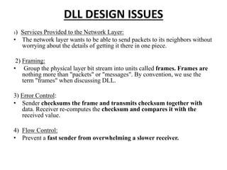
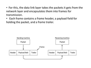
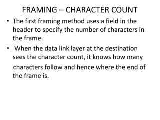
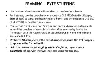
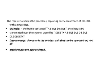
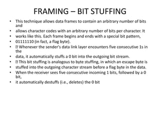
DATA LINK LAYER
CHAPTER 3.
OVERVIEW OF DLL
• The data link layer transforms the physical
layer, a raw transmission facility, to a link
responsible for node-to-node (hop-to-hop)
communication.
• Specific responsibilities of the data link layer
include framing, addressing, flow control,error
control, and media access control.
DLL DESIGN ISSUES
1) Services Provided to the Network Layer:
• The network layer wants to be able to send packets to its neighbors without
worrying about the details of getting it there in one piece.
2) Framing:
• Group the physical layer bit stream into units called frames. Frames are
nothing more than "packets" or "messages". By convention, we use the
term "frames" when discussing DLL.
3) Error Control:
• Sender checksums the frame and transmits checksum together with
data. Receiver re-computes the checksum and compares it with the
received value.
4) Flow Control:
• Prevent a fast sender from overwhelming a slower receiver.
DATA LINK LAYER DESIGN ISSUES
• Providing a well-defined service interface to
the network layer.
• Dealing with transmission errors.
• Regulating the flow of data so that slow
receivers are not swamped by fast senders.
• For this, the data link layer takes the packets it gets from the
network layer and encapsulates them into frames for
transmission.
• Each frame contains a frame header, a payload field for
holding the packet, and a frame trailer.
SERVICES PROVIDED TO THE
NETWORK LAYER
• The function of the data link layer is to provide services to the
network layer.
• The principal service is transferring data from the network layer
on the source machine to the network layer on the destination
machine.
• The data link layer can be designed to offer various services.
• The actual services offered can vary from system to system.
• Three reasonable possibilities that are commonly provided are
• 1) Unacknowledged Connectionless service
• 2) Acknowledged Connectionless service
• 3) Acknowledged Connection-Oriented service
UNACKNOWLEDGED CONNECTIONLESS
SERVICE
• Unacknowledged connectionless service consists of having
the source machine send independent frames to the
destination machine without having the destination machine
acknowledge them.
• No logical connection is established beforehand or released
afterward. If a frame is lost due to noise on the line, no
attempt is made to detect the loss or recover from it in the
data link layer.
• This class of service is appropriate when the error rate is very
low so that recovery is left to higher layers. It is also
appropriate for realtime traffic, such as voice, in which late
data are worse than bad data.
Most LANs use unacknowledged connectionless service in the
data link layer.
ACKNOWLEDGED CONNECTIONLESS SERVICE
• When this service is offered, there are still no logical connections
used, but each frame sent is individually acknowledged.
• In this way, the sender knows whether a frame has arrived correctly.
• If it has not arrived within a specified time interval, it can be sent
again. This service is useful over unreliable channels, such as wireless
systems.
• Adding Ack in the DLL rather than in the Network Layer is just an
optimization and not a requirement. If individual frames are
acknowledged and retransmitted, entire packets get through much
faster.
• On reliable channels, such as fiber, the overhead of a heavyweight
data link protocol may be unnecessary, but on wireless channels,
with their inherent unreliability, it is well worth the cost.
ACKNOWLEDGED CONNECTION-ORIENTED SERVICE
• Here, the source and destination machines establish a connection before
any data are transferred. Each frame sent over the connection is numbered,
and the data link layer guarantees that each frame sent is indeed received.
• Furthermore, it guarantees that each frame is received exactly once and that
all frames are received in the right order.
• When connection-oriented service is used, transfers go through three
distinct phases.
• In the first phase, the connection is established by having both sides
initialize variables and counters needed to keep track of which frames have
been received and which ones have not.
• In the second phase, one or more frames are actually transmitted.
• In the third and final phase, the connection is released, freeing up the
variables, buffers, and other resources used to maintain the connection.
PLACEMENT OF DATA LINK PROTOCOL
• FRAMING:
• DLL translates the physical layer's raw bit stream into
discrete units (messages) called frames.
• How can frame be transmitted so the receiver can detect
frame boundaries? That is, how can the receiver
recognize the start and end of a frame?
• Types of Framing:
• Character Count
• Flag byte with Byte Stuffing
• Starting and ending flag with bite stuffing
• Encoding Violations.
FRAMING – CHARACTER COUNT
• The first framing method uses a field in the
header to specify the number of characters in
the frame.
• When the data link layer at the destination
sees the character count, it knows how many
characters follow and hence where the end of
the frame is.
FRAMING – BYTE STUFFING
• Use reserved characters to indicate the start and end of a frame.
• For instance, use the two-character sequence DLE STX (Data-Link Escape,
Start of Text) to signal the beginning of a frame, and the sequence DLE ETX
(End of TeXt) to flag the frame's end.
• The second framing method, Starting and ending character stuffing, gets
around the problem of resynchronization after an error by having each
frame start with the ASCII character sequence DLE STX and end with the
sequence DLE ETX.
• Problem: What happens if the two-character sequence DLE ETX happens
to appear in the frame itself?
• Solution: Use character stuffing; within the frame, replace every
occurrence of DLE with the two-character sequence DLE DLE.
The receiver reverses the processes, replacing every occurrence of DLE DLE
with a single DLE.
• Example: If the frame contained ``A B DLE D E DLE'', the characters
• transmitted over the channel would be ``DLE STX A B DLE DLE D E DLE
• DLE DLE ETX''.
• Disadvantage: character is the smallest unit that can be operated on; not
all
• architectures are byte oriented.
Byte stuffing and unstuffing
FRAMING – BIT STUFFING
• This technique allows data frames to contain an arbitrary number of bits
and
• allows character codes with an arbitrary number of bits per character. It
• works like this. Each frame begins and ends with a special bit pattern,
• 01111110 (in fact, a flag byte).
• Whenever the sender's data link layer encounters five consecutive 1s in
the
• data, it automatically stuffs a 0 bit into the outgoing bit stream.
• This bit stuffing is analogous to byte stuffing, in which an escape byte is
• stuffed into the outgoing character stream before a flag byte in the data.
• When the receiver sees five consecutive incoming 1 bits, followed by a 0
bit,
• it automatically destuffs (i.e., deletes) the 0 bit

Data link layer

  • 1.
  • 2.
    OVERVIEW OF DLL •The data link layer transforms the physical layer, a raw transmission facility, to a link responsible for node-to-node (hop-to-hop) communication. • Specific responsibilities of the data link layer include framing, addressing, flow control,error control, and media access control.
  • 4.
    DLL DESIGN ISSUES 1)Services Provided to the Network Layer: • The network layer wants to be able to send packets to its neighbors without worrying about the details of getting it there in one piece. 2) Framing: • Group the physical layer bit stream into units called frames. Frames are nothing more than "packets" or "messages". By convention, we use the term "frames" when discussing DLL. 3) Error Control: • Sender checksums the frame and transmits checksum together with data. Receiver re-computes the checksum and compares it with the received value. 4) Flow Control: • Prevent a fast sender from overwhelming a slower receiver.
  • 5.
    DATA LINK LAYERDESIGN ISSUES • Providing a well-defined service interface to the network layer. • Dealing with transmission errors. • Regulating the flow of data so that slow receivers are not swamped by fast senders.
  • 6.
    • For this,the data link layer takes the packets it gets from the network layer and encapsulates them into frames for transmission. • Each frame contains a frame header, a payload field for holding the packet, and a frame trailer.
  • 7.
    SERVICES PROVIDED TOTHE NETWORK LAYER • The function of the data link layer is to provide services to the network layer. • The principal service is transferring data from the network layer on the source machine to the network layer on the destination machine. • The data link layer can be designed to offer various services. • The actual services offered can vary from system to system. • Three reasonable possibilities that are commonly provided are • 1) Unacknowledged Connectionless service • 2) Acknowledged Connectionless service • 3) Acknowledged Connection-Oriented service
  • 8.
    UNACKNOWLEDGED CONNECTIONLESS SERVICE • Unacknowledgedconnectionless service consists of having the source machine send independent frames to the destination machine without having the destination machine acknowledge them. • No logical connection is established beforehand or released afterward. If a frame is lost due to noise on the line, no attempt is made to detect the loss or recover from it in the data link layer. • This class of service is appropriate when the error rate is very low so that recovery is left to higher layers. It is also appropriate for realtime traffic, such as voice, in which late data are worse than bad data. Most LANs use unacknowledged connectionless service in the data link layer.
  • 9.
    ACKNOWLEDGED CONNECTIONLESS SERVICE •When this service is offered, there are still no logical connections used, but each frame sent is individually acknowledged. • In this way, the sender knows whether a frame has arrived correctly. • If it has not arrived within a specified time interval, it can be sent again. This service is useful over unreliable channels, such as wireless systems. • Adding Ack in the DLL rather than in the Network Layer is just an optimization and not a requirement. If individual frames are acknowledged and retransmitted, entire packets get through much faster. • On reliable channels, such as fiber, the overhead of a heavyweight data link protocol may be unnecessary, but on wireless channels, with their inherent unreliability, it is well worth the cost.
  • 10.
    ACKNOWLEDGED CONNECTION-ORIENTED SERVICE •Here, the source and destination machines establish a connection before any data are transferred. Each frame sent over the connection is numbered, and the data link layer guarantees that each frame sent is indeed received. • Furthermore, it guarantees that each frame is received exactly once and that all frames are received in the right order. • When connection-oriented service is used, transfers go through three distinct phases. • In the first phase, the connection is established by having both sides initialize variables and counters needed to keep track of which frames have been received and which ones have not. • In the second phase, one or more frames are actually transmitted. • In the third and final phase, the connection is released, freeing up the variables, buffers, and other resources used to maintain the connection.
  • 11.
    PLACEMENT OF DATALINK PROTOCOL
  • 12.
    • FRAMING: • DLLtranslates the physical layer's raw bit stream into discrete units (messages) called frames. • How can frame be transmitted so the receiver can detect frame boundaries? That is, how can the receiver recognize the start and end of a frame? • Types of Framing: • Character Count • Flag byte with Byte Stuffing • Starting and ending flag with bite stuffing • Encoding Violations.
  • 14.
    FRAMING – CHARACTERCOUNT • The first framing method uses a field in the header to specify the number of characters in the frame. • When the data link layer at the destination sees the character count, it knows how many characters follow and hence where the end of the frame is.
  • 16.
    FRAMING – BYTESTUFFING • Use reserved characters to indicate the start and end of a frame. • For instance, use the two-character sequence DLE STX (Data-Link Escape, Start of Text) to signal the beginning of a frame, and the sequence DLE ETX (End of TeXt) to flag the frame's end. • The second framing method, Starting and ending character stuffing, gets around the problem of resynchronization after an error by having each frame start with the ASCII character sequence DLE STX and end with the sequence DLE ETX. • Problem: What happens if the two-character sequence DLE ETX happens to appear in the frame itself? • Solution: Use character stuffing; within the frame, replace every occurrence of DLE with the two-character sequence DLE DLE.
  • 17.
    The receiver reversesthe processes, replacing every occurrence of DLE DLE with a single DLE. • Example: If the frame contained ``A B DLE D E DLE'', the characters • transmitted over the channel would be ``DLE STX A B DLE DLE D E DLE • DLE DLE ETX''. • Disadvantage: character is the smallest unit that can be operated on; not all • architectures are byte oriented.
  • 19.
  • 20.
    FRAMING – BITSTUFFING • This technique allows data frames to contain an arbitrary number of bits and • allows character codes with an arbitrary number of bits per character. It • works like this. Each frame begins and ends with a special bit pattern, • 01111110 (in fact, a flag byte). • Whenever the sender's data link layer encounters five consecutive 1s in the • data, it automatically stuffs a 0 bit into the outgoing bit stream. • This bit stuffing is analogous to byte stuffing, in which an escape byte is • stuffed into the outgoing character stream before a flag byte in the data. • When the receiver sees five consecutive incoming 1 bits, followed by a 0 bit, • it automatically destuffs (i.e., deletes) the 0 bit