Download to read offline

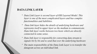
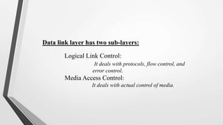
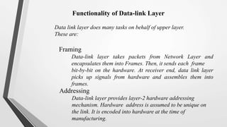
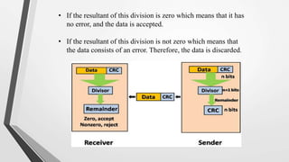
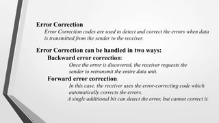
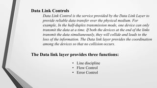
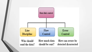

El nivel de enlace de datos es la segunda capa del modelo OSI, responsable de la conversión de flujos de datos en señales y su transferencia entre dos hosts conectados, incluyendo tareas de corrección de errores, control de flujo y encapsulamiento de paquetes en tramas. Incluye dos subcapas: control de enlace lógico y control de acceso al medio, y utiliza diversas técnicas para detectar y corregir errores, como la verificación de paridad y la verificación de redundancia cíclica (CRC). Además, gestiona la sincronización y el acceso multipunto para evitar colisiones en la transmisión de datos.


![Unit 2 [autosaved]](https://cdn.slidesharecdn.com/ss_thumbnails/unit-2autosaved-210914023404-thumbnail.jpg?width=640&height=640&fit=bounds)


