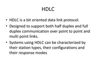
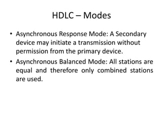
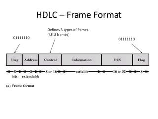
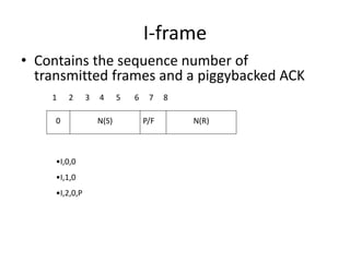
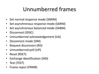
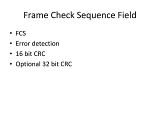
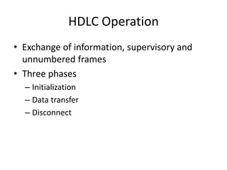
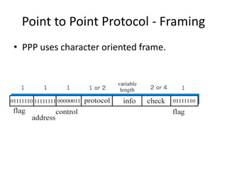
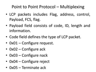
UNIT II
HDLC
• HDLC is a bit oriented data link protocol.
• Designed to support both half duplex and full
duplex communication over point to point and
multi point links.
• Systems using HDLC can be characterized by
their station types, their configurations and
their response modes
HDLC – Station Types
• Three types of stations: Primary and
Secondary.
• Primary Station: Sends commands to
secondary stations.
• Secondary Station: Issues responds to
commands issued by primary station.
• Combined station: Acts as both primary or
secondary station.
HDLC – Configurations
• Configuration refers to the relationship of hardware
devices on a link.
• Stations can be configured in three ways: Unbalanced,
Symmetric and Balanced.
• Unbalanced Configuration: Master – Slave
Configuration. One device is primary and other devices
are secondary devices.
• Symmetric Configuration: Each physical station on a
link consists of two logical stations: One primary and
secondary.
• Balanced Configuration: Both stations in a Point to
Point topology are of combined type.
HDLC – Modes
• 3 Modes: NRM, ARM, ABM
• Normal Response Mode: Refers to standard
primary – secondary relationship. Secondary
device must have permission from the primary
device before transmitting. Once permission
has been granted, the secondary may initiate
a response transmission of one or more
frames.
HDLC – Modes
• Asynchronous Response Mode: A Secondary
device may initiate a transmission without
permission from the primary device.
• Asynchronous Balanced Mode: All stations are
equal and therefore only combined stations
are used.
HDLC – Frame Format
01111110 01111110
Defines 3 types of frames
(I,S,U frames)
HDLC – Frame
• Delimit frame at both ends
• 01111110
• Receiver hunts for flag sequence to synchronize
• Bit stuffing used to avoid confusion with data
containing 01111110
– The transmitter inserts 0 bit after every sequence of
five 1s with the exception of flag fields
– If receiver detects five 1s it checks next bit
• If 0, it is deleted
• If 1 and seventh bit is 0 (i.e., 10), accept as flag
• If sixth and seventh bits 1 (i.e., 11), sender is indicating abort
Bit Stuffing
• Example with
possible errors
Bit Stuffing
• Example with
possible errors
Control Field
• Different for different frame type
– I-frame (information frame)
• data to be transmitted to user (next layer up)
• Flow and error control piggybacked on information frames
– S-frame (Supervisory frame)
• Used for flow and error control
– U-frame (Unnumbered frame)
• supplementary link control
• First one or two bits of control filed identify
frame type
Control Field Diagram
Poll/Final Bit
• Use depends on context
• Command frame
– P bit : used for poll from primary
– 1 to solicit (poll) response from peer
• Response frame
– F bit : used for response from secondary
– 1 indicates response to soliciting command
I-frame
• Contains the sequence number of
transmitted frames and a piggybacked ACK
1 2 3 4 5 6 7 8
0 N(S) P/F N(R)
•I,0,0
•I,1,0
•I,2,0,P
S-frame
• Used for flow and error control
1 2 3 4 5 6 7 8
1 S P/F N(R)
•RR --- receive ready
•RNR --- receive not ready
•REJ --- reject on frame N(R)
•SREJ --- selective reject on N(R)
0
U-frame
• Mode setting, recovery, connect/diconnect
1 2 3 4 5 6 7 8
1 M P/F M
1
Unnumbered
function bits
Unnumberred frames
• Set normal response mode (SNRM)
• Set asynchronous response mode (SARM)
• Set asynchronous balanced mode (SABM)
• Disconnect (DISC)
• Unnumberred acknowledgement (UA)
• Disconnect mode (DM)
• Request disconnect (RD)
• Unnumberred poll (UP)
• Reset (RSET)
• Exchange identification (XID)
• Test (TEST)
• Frame reject (FRMR)
Information Field
• Only in information and some unnumbered
frames
• Must contain integral number of octets
• Variable length
Frame Check Sequence Field
• FCS
• Error detection
• 16 bit CRC
• Optional 32 bit CRC
HDLC Operation
• Exchange of information, supervisory and
unnumbered frames
• Three phases
– Initialization
– Data transfer
– Disconnect
Examples of Operation (1)
Examples of Operation (2)
Point to Point Protocol
• Common protocol for point to point access is
PPP.
• Millions of internet users who need to
connect their home computers to the server
of an ISP use PPP.
• To control and manage transfer of data, PPP is
used.
Point to Point Protocol - Services
• PPP defines the format of the frame to be
exchanged between devices.
• It also defines how two devices can negotiate
the establishment of the link and exchange of
data.
• New version of PPP provides connections over
multiple links.
• PPP provides network address configuration.
Point to Point Protocol - Services
• PPP does not provide flow control.
• Sender send several frames one after the
other with no concern about overwhelming
the receiver.
• PPP has error control. CRC mechanism is used.
If error found, the frames are discarded.
Point to Point Protocol - Framing
• PPP uses character oriented frame.
Point to Point Protocol - Framing
• Flag: Starts with 1 byte flag : 01111110
• Address: Constant value 11111111 –
broadcast address.
• Protocol: Defines what is being carried in data
field. Either user data or other information. 2
bytes long.
• Payload field: Carries either user data or other
information. Maximum of 1500 bytes.
• FCS: 2 byte or 4 byte used for CRC.
Point to Point Protocol – Transition
Phases
• Transition starts with dead state – No active
carrier.
• Establish state: When one of the two nodes
starts the communication, the connection
goes to establish state.
• In this state, options are negotiated between
two parties. Two parties agree that they need
authentication – required steps are
performed.
Point to Point Protocol – Transition Phases
• Data transfer takes place in open state.
• When connection reaches this state, the
exchange of data packets can be started.
• The connection remains in this state until one
of the endpoints wants to terminate the
connection.
• In this situation, the system goes to terminate
state.
• The system remains in this state until the
carrier is dropped which moves the system to
dead state.
Point to Point Protocol – Multiplexing
• PPP uses set of protocols to establish the link.
• Link control protocol and Network control
Protocol.
• Link control protocol: Responsible for
establishing, maintaining, configuring and
terminating links.
• Provides negotiation mechanism to set
options between two end points.
• Both endpoints of the link must reach an
agreement about the options before the link
can be established.
Point to Point Protocol – Multiplexing
• LCP packets includes Flag, address, control,
Payload, FCS, flag.
• Payload field consists of code, ID, length and
information.
• Code field defines the type of LCP packet.
• 0x01 – Configure request.
• 0x02 – Configure ack
• 0x03 – Configure nack
• 0x04 – Configure reject
• 0x05 – Terminate ack
Point to Point Protocol – Multiplexing
• 0x06 – Terminate ACK
• 0x07 - Code reject
• 0x08 – Protocol reject
• 0x09 – Echo request
• 0x0A – Echo reply
• 0x0B – Discard request
• ID field holds a value that matches a request
with reply.
• Length field defines the length of the entire
LCP packet. Information field contains data.
Point to Point Protocol – Authentication Protocol
• Authentication – Validating the identity of a
user who needs to access a set of resources.
• Two protocols: Password Authentication
Protocol; Challenge Handshake authentication
Protocol.
• PAP – Two step process
– User who wants to access a system sends an
authentication identification and a password.
– The system checks the validity of the identification
and the password and either accepts or denies the
connection.
Point to Point Protocol – Authentication Protocol
• Challenge Handshake Authentication Protocol is a three way
handshaking authentication protocol that provides security
than PAP.
• In this method password is kept secret.
• The system sends the user a challenge packet containing a
challenge value
• The user applies a predefined function that takes the
challenge value and the user’s own password and creates a
result. The user sends the result in the response packet to the
system.
• The system does the same. It applies the same function and
creates a result. If both results are same access is granted.
Point to Point Protocol – NCP
• One NCP protocol is Internet Protocol Control Protocol (IPCP).
• This protocol configures the link used to carry IP packets in
the internet.
• IPCP packets includes Flag, address, control, Payload, FCS,
flag. Payload field consists of code, ID, length and information.
Code field defines the type of LCP packet.
• 0x01 – Configure request.
• 0x02 – Configure ack
• 0x03 – Configure nack
• 0x04 – Configure reject
• 0x05 – Terminate request
• 0x06 – Terminate ack
• 0x07 – Code reject

UNIT II.ppt Computer networks protocol explanation

  • 1.
  • 2.
    HDLC • HDLC isa bit oriented data link protocol. • Designed to support both half duplex and full duplex communication over point to point and multi point links. • Systems using HDLC can be characterized by their station types, their configurations and their response modes
  • 3.
    HDLC – StationTypes • Three types of stations: Primary and Secondary. • Primary Station: Sends commands to secondary stations. • Secondary Station: Issues responds to commands issued by primary station. • Combined station: Acts as both primary or secondary station.
  • 4.
    HDLC – Configurations •Configuration refers to the relationship of hardware devices on a link. • Stations can be configured in three ways: Unbalanced, Symmetric and Balanced. • Unbalanced Configuration: Master – Slave Configuration. One device is primary and other devices are secondary devices. • Symmetric Configuration: Each physical station on a link consists of two logical stations: One primary and secondary. • Balanced Configuration: Both stations in a Point to Point topology are of combined type.
  • 5.
    HDLC – Modes •3 Modes: NRM, ARM, ABM • Normal Response Mode: Refers to standard primary – secondary relationship. Secondary device must have permission from the primary device before transmitting. Once permission has been granted, the secondary may initiate a response transmission of one or more frames.
  • 6.
    HDLC – Modes •Asynchronous Response Mode: A Secondary device may initiate a transmission without permission from the primary device. • Asynchronous Balanced Mode: All stations are equal and therefore only combined stations are used.
  • 7.
    HDLC – FrameFormat 01111110 01111110 Defines 3 types of frames (I,S,U frames)
  • 8.
    HDLC – Frame •Delimit frame at both ends • 01111110 • Receiver hunts for flag sequence to synchronize • Bit stuffing used to avoid confusion with data containing 01111110 – The transmitter inserts 0 bit after every sequence of five 1s with the exception of flag fields – If receiver detects five 1s it checks next bit • If 0, it is deleted • If 1 and seventh bit is 0 (i.e., 10), accept as flag • If sixth and seventh bits 1 (i.e., 11), sender is indicating abort
  • 9.
    Bit Stuffing • Examplewith possible errors
  • 10.
    Bit Stuffing • Examplewith possible errors
  • 11.
    Control Field • Differentfor different frame type – I-frame (information frame) • data to be transmitted to user (next layer up) • Flow and error control piggybacked on information frames – S-frame (Supervisory frame) • Used for flow and error control – U-frame (Unnumbered frame) • supplementary link control • First one or two bits of control filed identify frame type
  • 12.
  • 13.
    Poll/Final Bit • Usedepends on context • Command frame – P bit : used for poll from primary – 1 to solicit (poll) response from peer • Response frame – F bit : used for response from secondary – 1 indicates response to soliciting command
  • 14.
    I-frame • Contains thesequence number of transmitted frames and a piggybacked ACK 1 2 3 4 5 6 7 8 0 N(S) P/F N(R) •I,0,0 •I,1,0 •I,2,0,P
  • 15.
    S-frame • Used forflow and error control 1 2 3 4 5 6 7 8 1 S P/F N(R) •RR --- receive ready •RNR --- receive not ready •REJ --- reject on frame N(R) •SREJ --- selective reject on N(R) 0
  • 16.
    U-frame • Mode setting,recovery, connect/diconnect 1 2 3 4 5 6 7 8 1 M P/F M 1 Unnumbered function bits
  • 17.
    Unnumberred frames • Setnormal response mode (SNRM) • Set asynchronous response mode (SARM) • Set asynchronous balanced mode (SABM) • Disconnect (DISC) • Unnumberred acknowledgement (UA) • Disconnect mode (DM) • Request disconnect (RD) • Unnumberred poll (UP) • Reset (RSET) • Exchange identification (XID) • Test (TEST) • Frame reject (FRMR)
  • 18.
    Information Field • Onlyin information and some unnumbered frames • Must contain integral number of octets • Variable length
  • 19.
    Frame Check SequenceField • FCS • Error detection • 16 bit CRC • Optional 32 bit CRC
  • 20.
    HDLC Operation • Exchangeof information, supervisory and unnumbered frames • Three phases – Initialization – Data transfer – Disconnect
  • 21.
  • 22.
  • 23.
    Point to PointProtocol • Common protocol for point to point access is PPP. • Millions of internet users who need to connect their home computers to the server of an ISP use PPP. • To control and manage transfer of data, PPP is used.
  • 24.
    Point to PointProtocol - Services • PPP defines the format of the frame to be exchanged between devices. • It also defines how two devices can negotiate the establishment of the link and exchange of data. • New version of PPP provides connections over multiple links. • PPP provides network address configuration.
  • 25.
    Point to PointProtocol - Services • PPP does not provide flow control. • Sender send several frames one after the other with no concern about overwhelming the receiver. • PPP has error control. CRC mechanism is used. If error found, the frames are discarded.
  • 26.
    Point to PointProtocol - Framing • PPP uses character oriented frame.
  • 27.
    Point to PointProtocol - Framing • Flag: Starts with 1 byte flag : 01111110 • Address: Constant value 11111111 – broadcast address. • Protocol: Defines what is being carried in data field. Either user data or other information. 2 bytes long. • Payload field: Carries either user data or other information. Maximum of 1500 bytes. • FCS: 2 byte or 4 byte used for CRC.
  • 28.
    Point to PointProtocol – Transition Phases • Transition starts with dead state – No active carrier. • Establish state: When one of the two nodes starts the communication, the connection goes to establish state. • In this state, options are negotiated between two parties. Two parties agree that they need authentication – required steps are performed.
  • 29.
    Point to PointProtocol – Transition Phases • Data transfer takes place in open state. • When connection reaches this state, the exchange of data packets can be started. • The connection remains in this state until one of the endpoints wants to terminate the connection. • In this situation, the system goes to terminate state. • The system remains in this state until the carrier is dropped which moves the system to dead state.
  • 30.
    Point to PointProtocol – Multiplexing • PPP uses set of protocols to establish the link. • Link control protocol and Network control Protocol. • Link control protocol: Responsible for establishing, maintaining, configuring and terminating links. • Provides negotiation mechanism to set options between two end points. • Both endpoints of the link must reach an agreement about the options before the link can be established.
  • 31.
    Point to PointProtocol – Multiplexing • LCP packets includes Flag, address, control, Payload, FCS, flag. • Payload field consists of code, ID, length and information. • Code field defines the type of LCP packet. • 0x01 – Configure request. • 0x02 – Configure ack • 0x03 – Configure nack • 0x04 – Configure reject • 0x05 – Terminate ack
  • 32.
    Point to PointProtocol – Multiplexing • 0x06 – Terminate ACK • 0x07 - Code reject • 0x08 – Protocol reject • 0x09 – Echo request • 0x0A – Echo reply • 0x0B – Discard request • ID field holds a value that matches a request with reply. • Length field defines the length of the entire LCP packet. Information field contains data.
  • 33.
    Point to PointProtocol – Authentication Protocol • Authentication – Validating the identity of a user who needs to access a set of resources. • Two protocols: Password Authentication Protocol; Challenge Handshake authentication Protocol. • PAP – Two step process – User who wants to access a system sends an authentication identification and a password. – The system checks the validity of the identification and the password and either accepts or denies the connection.
  • 34.
    Point to PointProtocol – Authentication Protocol • Challenge Handshake Authentication Protocol is a three way handshaking authentication protocol that provides security than PAP. • In this method password is kept secret. • The system sends the user a challenge packet containing a challenge value • The user applies a predefined function that takes the challenge value and the user’s own password and creates a result. The user sends the result in the response packet to the system. • The system does the same. It applies the same function and creates a result. If both results are same access is granted.
  • 35.
    Point to PointProtocol – NCP • One NCP protocol is Internet Protocol Control Protocol (IPCP). • This protocol configures the link used to carry IP packets in the internet. • IPCP packets includes Flag, address, control, Payload, FCS, flag. Payload field consists of code, ID, length and information. Code field defines the type of LCP packet. • 0x01 – Configure request. • 0x02 – Configure ack • 0x03 – Configure nack • 0x04 – Configure reject • 0x05 – Terminate request • 0x06 – Terminate ack • 0x07 – Code reject