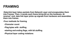
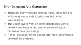
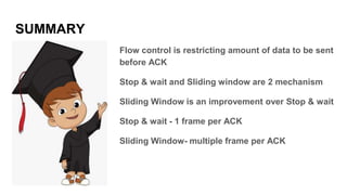
Data link layer
DATA LINK LAYER
Functionality of The Data link layer
•providing a well defined service interface
to the network layer.
•Dealing with transmission Error
•Regulating the flow of data
•Frame management
Relation between packet and frame
DATA LINK DESIGN ISSUES
•Services provided to the network layer
-function of data link layer
-principle service is transferring data from network layer
on source to network layer on destination
-on the source machine is an entity or process, handles
bits to the data link layer for transmission to the
destination
continue
•The data link layer can be designed to offer various
services. The actual services offered can vary form system
to system. Three reasonable possibilities that are
commonly provide are:
1. unacknowledged connectionless service:
-source sends data but no acknowledgement from receiver
-no logical connection
-no attempt to detect and recover the lost frame
-appropriate when error rate is very low like for real –time traffic, such
as voice in which late data are worse than bad data.
2. Acknowledge connectionless service
-sent frame is acknowledged by the receiver
-frame can be resent incase it has not arrived on specified time
-reliable than the previous
3. Acknowledge connection- oriented service
-most sophisticated service
-connection between sender and receiver is established before sending
frame
-frame sent over the connection is numbered
-guarantees that each frame sent is indeed received
FRAMING
•Data-link layer takes packets from Network Layer and encapsulates them
into Frames. Then, it sends each frame bit-by-bit on the hardware. At
receiver’ end, data link layer picks up signals from hardware and assembles
them into frames.
•Four methods for framing
-Character count
-Flag bytes with stuffing
-starting and ending flags, with bit stuffing
-Physical layer coding violations
Character count
-Uses a field in header to specify the number of
characters in the frame.
-The data link layer at the destination sees the
character count, it knows how many characters
follow and hence where the end of the frame is.
-gets around the problem of resynchronization after an
error by having each frame start and end with special
bytes, called flag byte
-if receiver ever loses synchronization, it can just search
for the flag byte to find the end of the current frame.
-Two consecutive flag bytes indicate the end of one frame
and start of the next one.
Problem with the strategy
-problem occurs while transferring binary data.
-flag byte’s bit pattern may occur in data
-this situation interfere with the farming.
Solution to the problem
-Insertion of special escape byte(ESC)
-Technique: Byte stuffing or character stuffing
-Thus framing flag byte can be distinguished from one in the data by the
absence or presence of an escape byte before it.
-
-What happens if an escape byte pattern occurs in the middle of the data?
--stuff another ESC byte before the ESC bit pattern in the data
Disadvantage of Byte stuffing
Closely tied to the use of 8-bit characters
Not all characters code use 8-bit characters . E.g
Unicode uses 16-bit characters.
Bit stuffing
•Allows data frames to contain any arbitrary number of bits per
character
•Each frame begins and ends with special bit pattern 01111110(flag
byte)
•When sender’s data link layer encounters five consecutive 1s in the
data , it automatically stuffs 0 bit into the out going stream
•Analogous to byte stuffing
•When receiver sees five consecutive 1s followed by 0 bit, it
automatically dyestuffs the 0 bit.
Physical layer coding violation
-Only applicable to networks in which encoding on physical medium
contains some redundancy
-For example, some lANs encode 1 bit by using 2 physical bits.
1 bit= high low pair
0 bit =low high pair
The scheme means that every data bit has a transition in the middle,
making it easy for the receiver to locate the bit boundaries
High-high and low-low used for delimiting frames in some protocol
Error Detection And Correction
● There are many reasons such as noise, cross-talk etc.,
which may cause data to get corrupted during
transmission.
● The upper layers work on some generalized view of
network architecture and are not aware of actual
hardware data processing.
● Hence, the upper layers expect error-free transmission
between the systems.
Types of Errors
Single bit error
In a frame, there is only one bit, anywhere though, which is
corrupt.
Types of Errors
Multiple bits error
Frame is received with more than one bits in corrupted state.
Types of Errors
Burst Error
Frame contains more than one consecutive bits corrupted.
Error Detection
● Parity Check
Error Detection
● Cyclic Redundancy
Check (CRC)
Error Correction
● Backward Error Correction When the receiver detects an error in
the data received, it requests back the sender to retransmit the data unit.
● Forward Error Correction When the receiver detects some error in
the data received, it executes error-correcting code, which helps it to auto-
recover and to correct some kinds of errors.
FLOW CONTROL
Problem: What to do when sender wants
to send frames faster than the capacity
of the receiver
RESULT: Frames are lost, because they are arriving too quickly!!
SOLUTION
- Introduce flow control
- Controlling the rate of frame transmission to a value which can be
handled by the receiver
What is flow control? => A set of procedures that tells the sender how much
data it is allowed to transmit before waiting for an acknowledgement from
the receiver.
The receiver can tell transmitter about adjusting the data flow rate to suit its
speed or even stop temporarily.
=>Receiver has a block of memory k/a buffer , which stores incoming data
until they are processed.
SO, If buffer is filled receiver should tell sender to stop transmission
Transmitter also has buffer for storing bits if transmission is stopped
Mechanisms of flow control
1) Stop and Wait
Stop and Wait!!
In this mechanism…
-then sender sends a packet and waits for an
acknowledgement before sending next.
-each packet has unique sequence number
- the packet sequence number is matched with that
the sequence number in ACK
Advantages and limitations of Stop and Wait
mechanism
Advantages of Stop and Wait
1) It can be used for noisy channels
2) It has both error and flow control mechanisms
3) It has a timer implementation
Disadvantages of Stop and Wait
1) Lesser Efficiency due to wastage
of resources
2) Only 1 frame sent at a time
3) Sender will have to wait at least
one round trip time before
sending next frame.
4) Waiting can be too long for a
slow n/w like satellite link
Mechanisms of flow control continued...
2) Sliding Window
Number of outbound frames is fixed
before an acknowledgement from
receiver.
Frames consist of sequence
number ,from 0 to (2^n)-1 i.e if n=3
bits, sequence: 0 to 7
Sending window => sender
maintains this window , consisting
of frames permitted to be sent
Receiver window => receiver
maintains this window,
consisting of frames that may be
received before ACK is sent
SUMMARY
Flow control is restricting amount of data to be sent
before ACK
Stop & wait and Sliding window are 2 mechanism
Sliding Window is an improvement over Stop & wait
Stop & wait - 1 frame per ACK
Sliding Window- multiple frame per ACK

Data link layer

  • 1.
  • 2.
  • 3.
    Functionality of TheData link layer •providing a well defined service interface to the network layer. •Dealing with transmission Error •Regulating the flow of data •Frame management
  • 4.
  • 5.
    DATA LINK DESIGNISSUES •Services provided to the network layer -function of data link layer -principle service is transferring data from network layer on source to network layer on destination -on the source machine is an entity or process, handles bits to the data link layer for transmission to the destination
  • 6.
    continue •The data linklayer can be designed to offer various services. The actual services offered can vary form system to system. Three reasonable possibilities that are commonly provide are: 1. unacknowledged connectionless service: -source sends data but no acknowledgement from receiver -no logical connection -no attempt to detect and recover the lost frame -appropriate when error rate is very low like for real –time traffic, such as voice in which late data are worse than bad data.
  • 7.
    2. Acknowledge connectionlessservice -sent frame is acknowledged by the receiver -frame can be resent incase it has not arrived on specified time -reliable than the previous 3. Acknowledge connection- oriented service -most sophisticated service -connection between sender and receiver is established before sending frame -frame sent over the connection is numbered -guarantees that each frame sent is indeed received
  • 8.
    FRAMING •Data-link layer takespackets from Network Layer and encapsulates them into Frames. Then, it sends each frame bit-by-bit on the hardware. At receiver’ end, data link layer picks up signals from hardware and assembles them into frames. •Four methods for framing -Character count -Flag bytes with stuffing -starting and ending flags, with bit stuffing -Physical layer coding violations
  • 9.
    Character count -Uses afield in header to specify the number of characters in the frame. -The data link layer at the destination sees the character count, it knows how many characters follow and hence where the end of the frame is.
  • 11.
    -gets around theproblem of resynchronization after an error by having each frame start and end with special bytes, called flag byte -if receiver ever loses synchronization, it can just search for the flag byte to find the end of the current frame. -Two consecutive flag bytes indicate the end of one frame and start of the next one.
  • 12.
    Problem with thestrategy -problem occurs while transferring binary data. -flag byte’s bit pattern may occur in data -this situation interfere with the farming.
  • 13.
    Solution to theproblem -Insertion of special escape byte(ESC) -Technique: Byte stuffing or character stuffing -Thus framing flag byte can be distinguished from one in the data by the absence or presence of an escape byte before it. - -What happens if an escape byte pattern occurs in the middle of the data? --stuff another ESC byte before the ESC bit pattern in the data
  • 15.
    Disadvantage of Bytestuffing Closely tied to the use of 8-bit characters Not all characters code use 8-bit characters . E.g Unicode uses 16-bit characters.
  • 16.
    Bit stuffing •Allows dataframes to contain any arbitrary number of bits per character •Each frame begins and ends with special bit pattern 01111110(flag byte) •When sender’s data link layer encounters five consecutive 1s in the data , it automatically stuffs 0 bit into the out going stream •Analogous to byte stuffing •When receiver sees five consecutive 1s followed by 0 bit, it automatically dyestuffs the 0 bit.
  • 18.
    Physical layer codingviolation -Only applicable to networks in which encoding on physical medium contains some redundancy -For example, some lANs encode 1 bit by using 2 physical bits. 1 bit= high low pair 0 bit =low high pair The scheme means that every data bit has a transition in the middle, making it easy for the receiver to locate the bit boundaries High-high and low-low used for delimiting frames in some protocol
  • 19.
    Error Detection AndCorrection ● There are many reasons such as noise, cross-talk etc., which may cause data to get corrupted during transmission. ● The upper layers work on some generalized view of network architecture and are not aware of actual hardware data processing. ● Hence, the upper layers expect error-free transmission between the systems.
  • 20.
    Types of Errors Singlebit error In a frame, there is only one bit, anywhere though, which is corrupt.
  • 21.
    Types of Errors Multiplebits error Frame is received with more than one bits in corrupted state.
  • 22.
    Types of Errors BurstError Frame contains more than one consecutive bits corrupted.
  • 23.
  • 24.
    Error Detection ● CyclicRedundancy Check (CRC)
  • 25.
    Error Correction ● BackwardError Correction When the receiver detects an error in the data received, it requests back the sender to retransmit the data unit. ● Forward Error Correction When the receiver detects some error in the data received, it executes error-correcting code, which helps it to auto- recover and to correct some kinds of errors.
  • 26.
    FLOW CONTROL Problem: Whatto do when sender wants to send frames faster than the capacity of the receiver
  • 27.
    RESULT: Frames arelost, because they are arriving too quickly!!
  • 28.
    SOLUTION - Introduce flowcontrol - Controlling the rate of frame transmission to a value which can be handled by the receiver What is flow control? => A set of procedures that tells the sender how much data it is allowed to transmit before waiting for an acknowledgement from the receiver.
  • 29.
    The receiver cantell transmitter about adjusting the data flow rate to suit its speed or even stop temporarily. =>Receiver has a block of memory k/a buffer , which stores incoming data until they are processed. SO, If buffer is filled receiver should tell sender to stop transmission Transmitter also has buffer for storing bits if transmission is stopped
  • 30.
    Mechanisms of flowcontrol 1) Stop and Wait
  • 31.
    Stop and Wait!! Inthis mechanism… -then sender sends a packet and waits for an acknowledgement before sending next. -each packet has unique sequence number - the packet sequence number is matched with that the sequence number in ACK
  • 32.
    Advantages and limitationsof Stop and Wait mechanism
  • 33.
    Advantages of Stopand Wait 1) It can be used for noisy channels 2) It has both error and flow control mechanisms 3) It has a timer implementation
  • 34.
    Disadvantages of Stopand Wait 1) Lesser Efficiency due to wastage of resources 2) Only 1 frame sent at a time 3) Sender will have to wait at least one round trip time before sending next frame. 4) Waiting can be too long for a slow n/w like satellite link
  • 35.
    Mechanisms of flowcontrol continued... 2) Sliding Window
  • 36.
    Number of outboundframes is fixed before an acknowledgement from receiver. Frames consist of sequence number ,from 0 to (2^n)-1 i.e if n=3 bits, sequence: 0 to 7 Sending window => sender maintains this window , consisting of frames permitted to be sent
  • 37.
    Receiver window =>receiver maintains this window, consisting of frames that may be received before ACK is sent
  • 39.
    SUMMARY Flow control isrestricting amount of data to be sent before ACK Stop & wait and Sliding window are 2 mechanism Sliding Window is an improvement over Stop & wait Stop & wait - 1 frame per ACK Sliding Window- multiple frame per ACK