Downloaded 335 times

![13
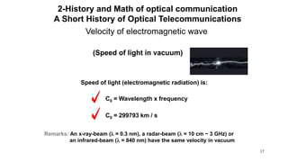
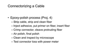
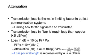
3. optical
window
Infrared
range
Visible
range
Singlemode
(1310 – 1650nm)
GOF Multimode
(850 – 1300nm)
POF
(520 – 650nm)
PCF
(650 – 850nm)
1. optical
window
1800 1600 1400 1200 1000 800 600 400
Wavelength [nm]
2. optical
window
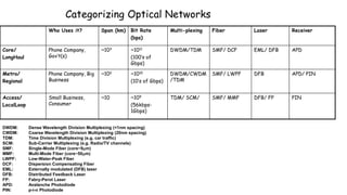
Wavelength range of optical
transmission
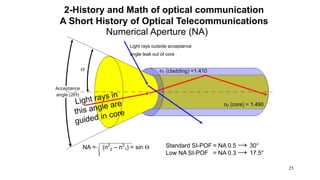
2-History and Math of optical communication](https://image.slidesharecdn.com/opticalcommunicationsystem-161227092405/85/Optical-communication-system-13-320.jpg)


![164
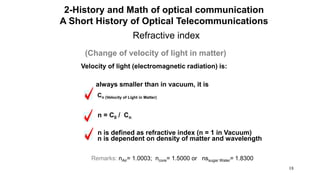
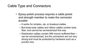
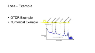
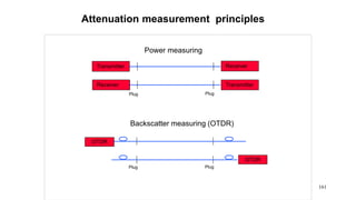
Power measurement :
link evaluation
Transmitter
2. Measuring the system’s attenuation
Receiver
FO System
Total attenuation [dB]
850 nm
Ð 0.74dBm
nm850
Ð 0.74dBm
nm850](https://image.slidesharecdn.com/opticalcommunicationsystem-161227092405/85/Optical-communication-system-164-320.jpg)


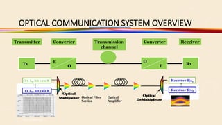
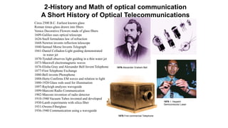
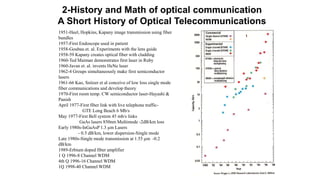
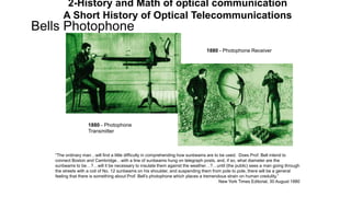
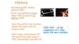
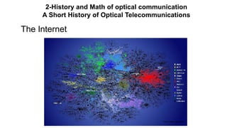
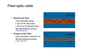
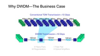
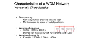
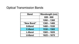
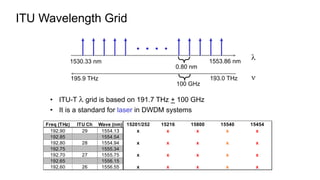
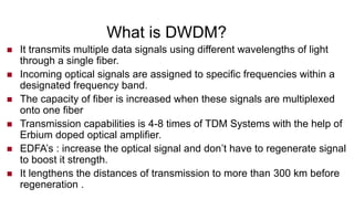
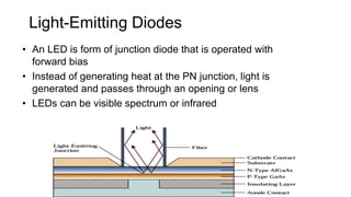
The document provides a comprehensive overview of optical communication systems, detailing their history, construction, and applications, along with the physics behind optical fiber technology. Key topics include the evolution of telecommunications, the types of optical fibers, their components, signal propagation, and challenges such as dispersion and attenuation. It also highlights advancements in fiber-optic technology and various transmission methods like wavelength division multiplexing.