Download to read offline

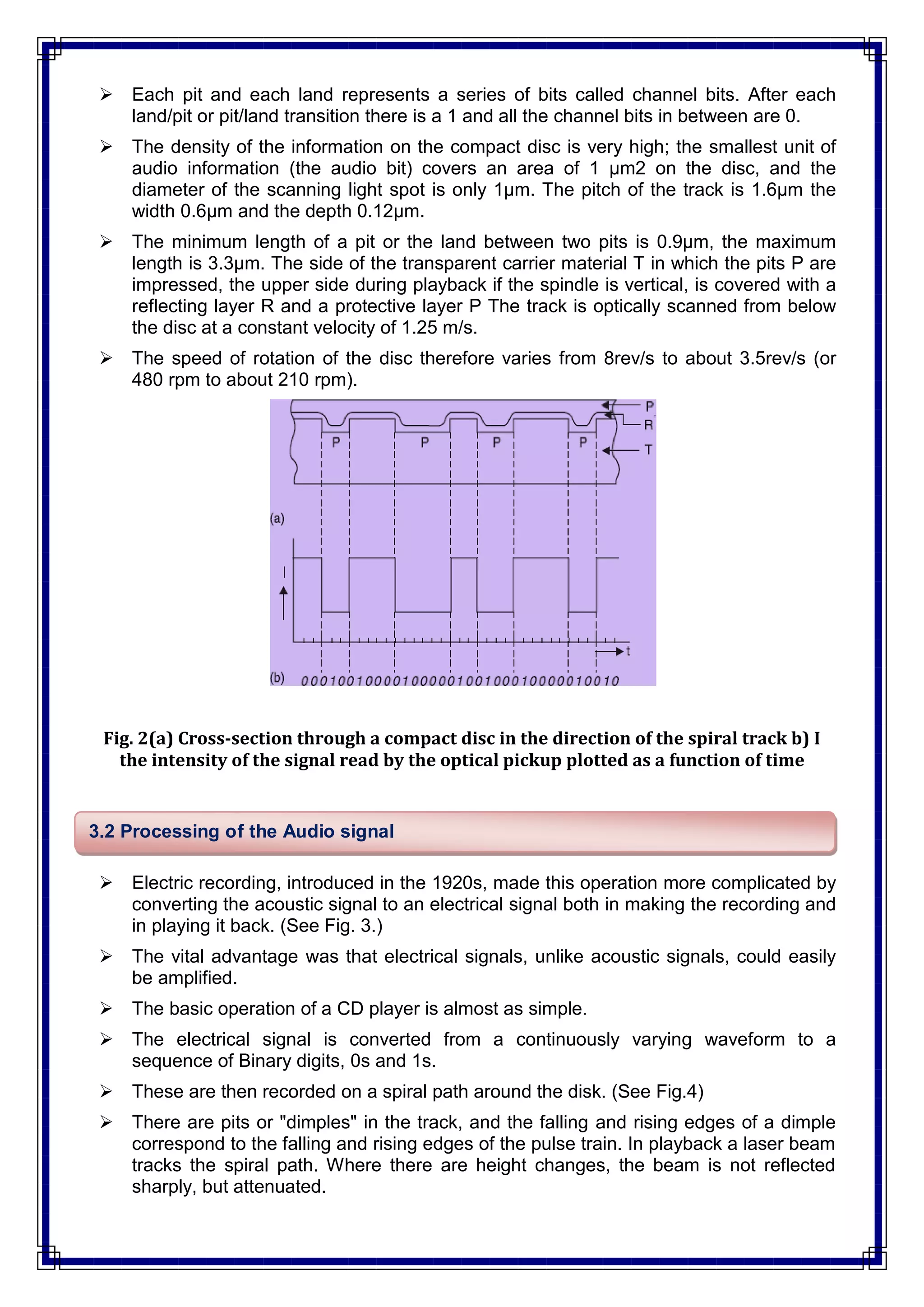


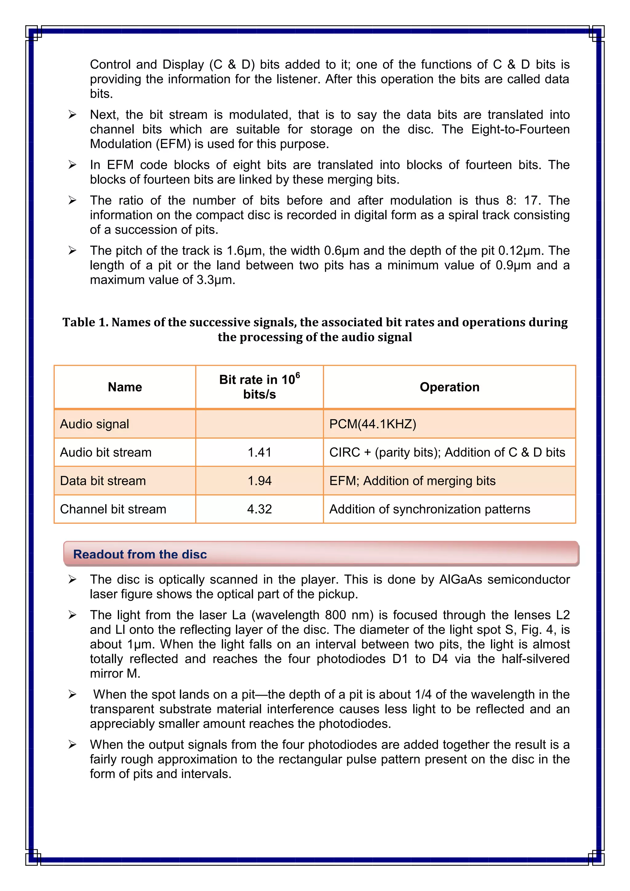


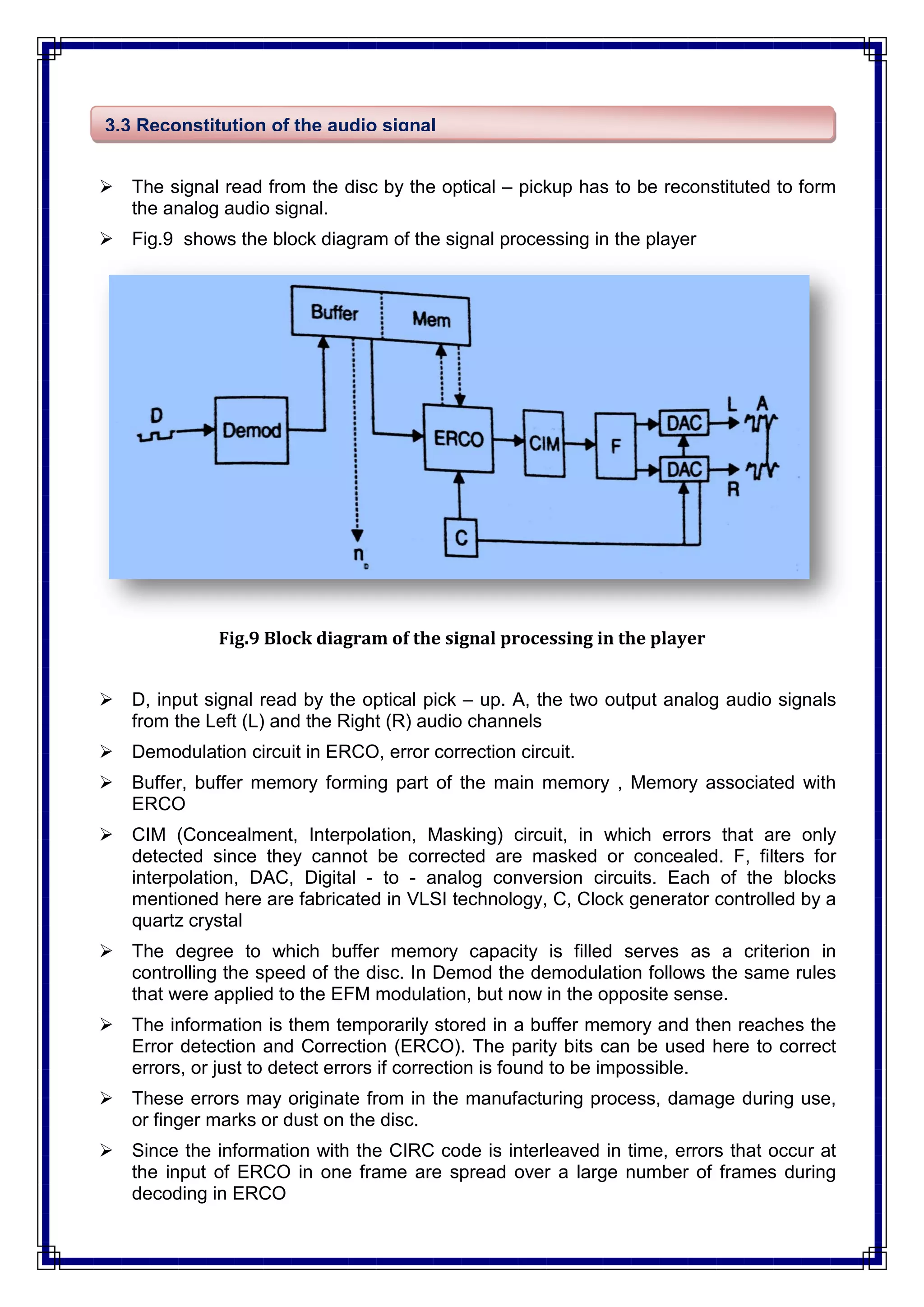


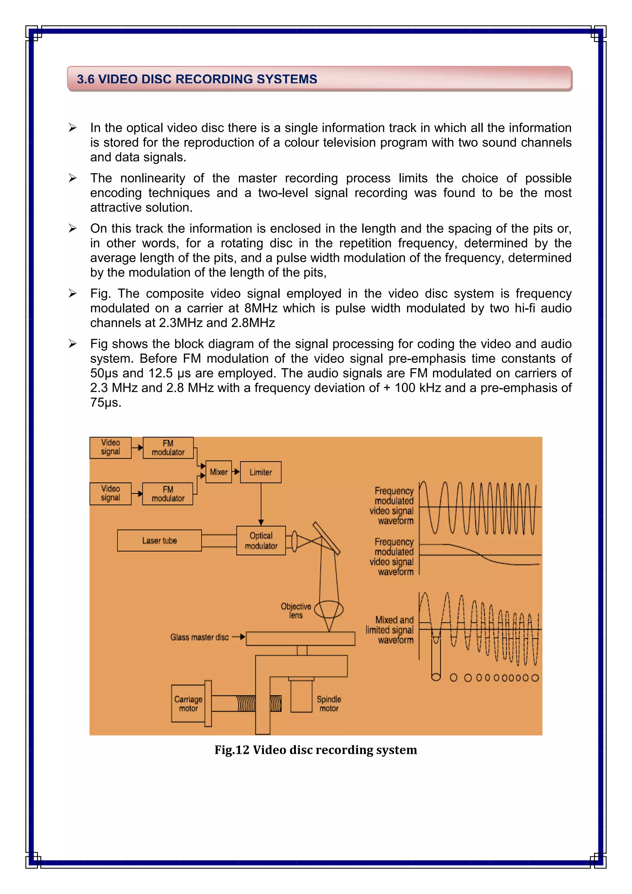
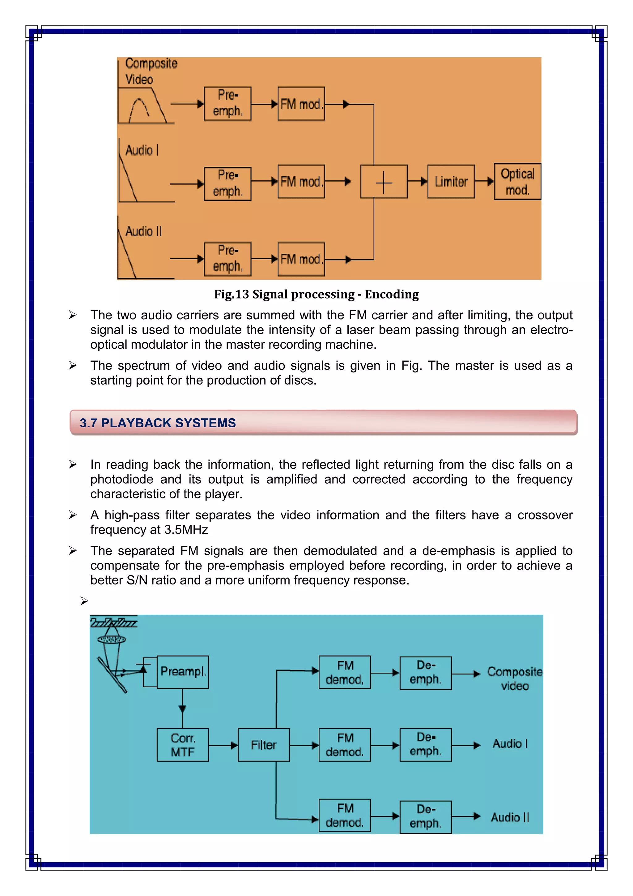
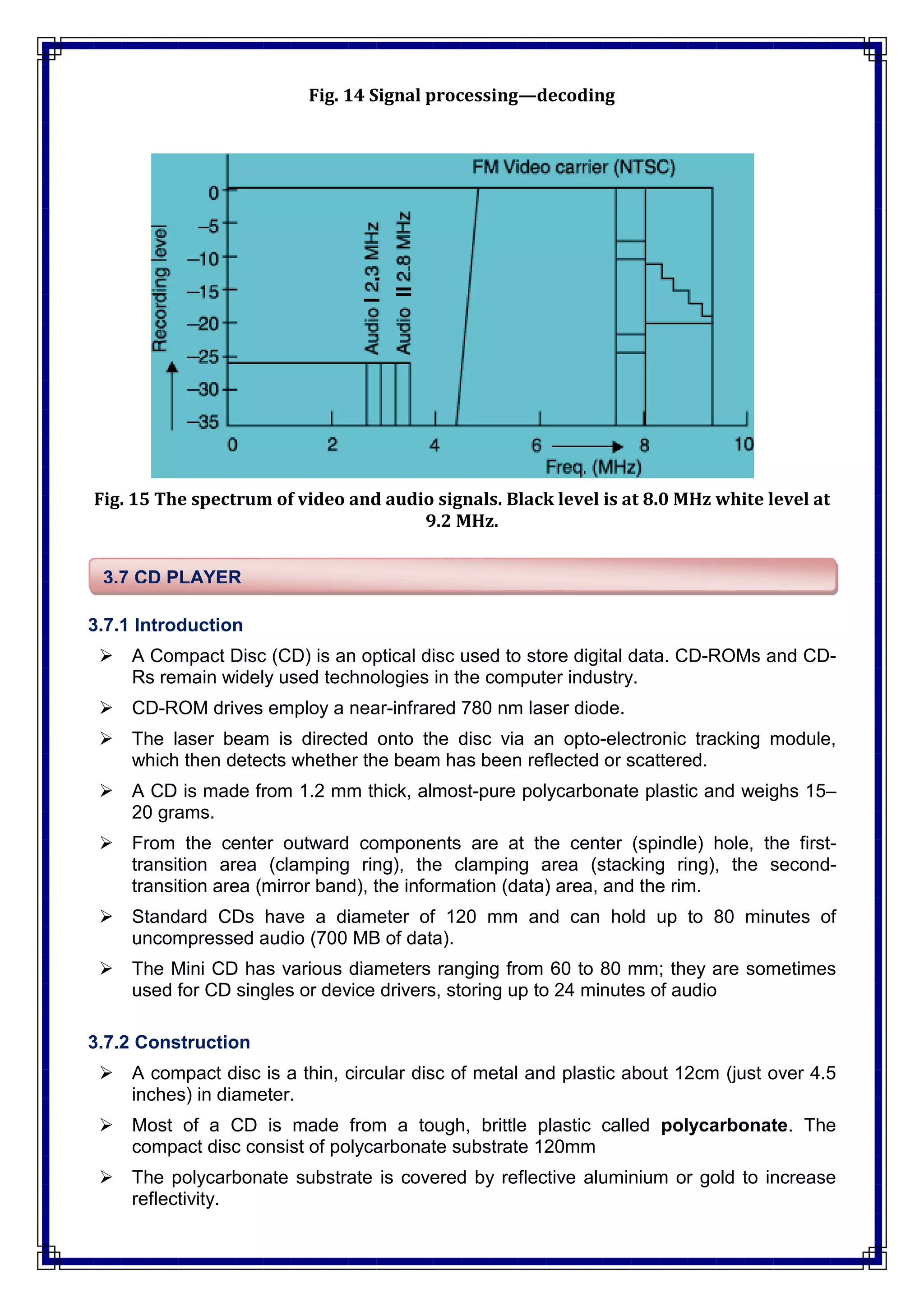


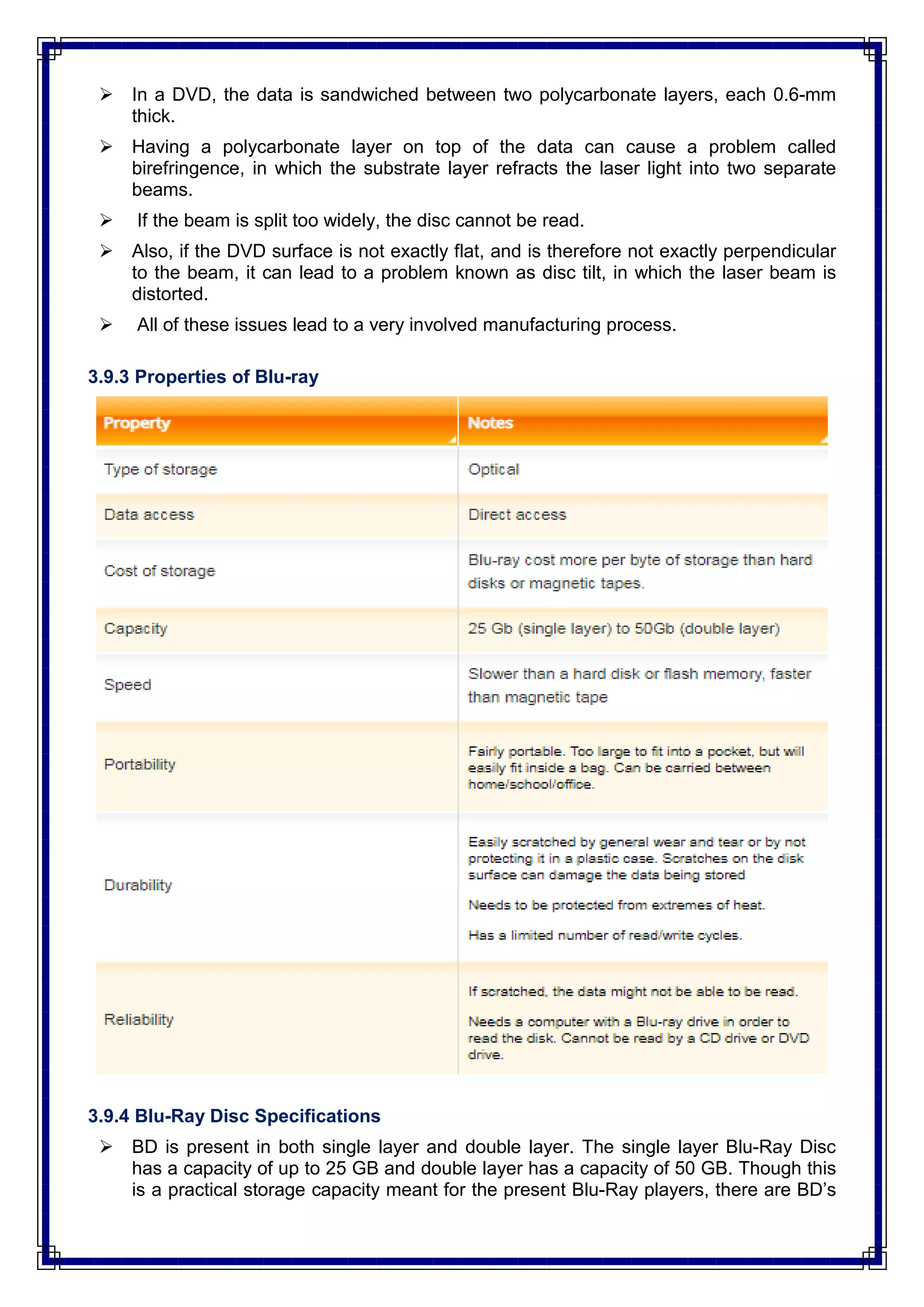


The document provides a detailed overview of optical recording and reproduction systems for audio and video discs, including the functioning of CD players, the structure of compact discs, and the processes involved in reading and converting signals. It highlights the advantages of digital recording such as superior sound quality, error correction capabilities, and durability. The document also references several textbooks and discusses the evolution of video disc technology.