Downloaded 208 times
![Dept of EEE LI-FI TECHNOLOGY
AIT Palakkad 39
REFERENCES
1] S. Dimitrov and H. Haas. Principles of LED Light Communications–Towards Networked
LiFi. Cambridge University Press, Mar. 2015.
2] P.Chandhar and S. Das. Area Spectral Efficiency of Co-Channel Deployed OFDMA
Femtocell Networks. IEEE Trans. Wireless Commun., 13(7):3524–3538, July 2014.
3] V. Chandrasekhar, J. Andrews, and A. Gatherer. Femtocell Networks: A Survey. IEEE
Commun. Mag., 46(9):59–67, 2008.
4] W. C. Cheung, T. Quek, and M. Kountouris. Throughput Optimization, Spectrum
Allocation, and Access Control in Two-Tier Femtocell Networks. IEEE J. Sel. Areas
Commun., 30(3):561–574, Apr. 2012.
5] S. Dimitrov and H. Haas. Information Rate of OFDM Based Optical Wireless
Communication Systems With Nonlinear Distortion. J. Lightw. Technol., 31(6):918–929,
March 2013.
6] J. Andrews, F. Baccelli, and R. Ganti. A tractable approach to coverage and rate in
cellular networks. IEEE Trans. on Commun., 59(11):3122–3134, Nov. 2011.
7] V. Donald. Advanced mobile phone service: The cellular concept. The Bell System
Technical Journal, 58(1):15– 41, Jan 1979.
8] EuropeanStandardEN12464-1. LightingofIndoorWork Places, Jan. 2009.
9] H. Haas. Wireless Data from Every Light Bulb. TED Website, Aug. 2011.
10] H. Haas. High-speed Wireless Networking Using Visible Light. SPIE Newsroom, Apr.
19 2013.](https://image.slidesharecdn.com/pdfjoiner1-170117062252/85/Li-Fi-Technology-49-320.jpg)
![Dept of EEE LI-FI TECHNOLOGY
AIT Palakkad 40
11] H S..Jo, P. Xia and J. Andrews. Downlink Femtocell Networks: Open or Closed? In
Proc. of IEEE Int. Commun. Conf. (ICC), pages 1–5, June 2011.
12] D. Stoyan, W. S. Kendall, and J. Mecke. Stochastic Geometry and its Applications. John
Wiley and Sons, 2nd edition, 1995.
13] D.Tsonev et al. A 3-Gb/s Single-LED OFDM-Based Wireless VLC Link Using a
Gallium Nitride µLED. IEEE Photon. Technol. Lett., 26(7):637–640, Apr. 2014.
14] F. Xiong. Digital Modulation Techniques. Artech House Publishers, 2nd edition edition,
2006.](https://image.slidesharecdn.com/pdfjoiner1-170117062252/85/Li-Fi-Technology-50-320.jpg)

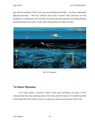
This document is a seminar report on Li-Fi technology submitted by Sanjush S. in partial fulfillment of a Bachelor of Technology degree. It provides an abstract, table of contents, and covers topics such as the history of Li-Fi, how Li-Fi works using visible light communication, Li-Fi technology components including transmitters and receivers, modulation techniques, standards, applications, and comparisons with Wi-Fi technology. The report was certified and acknowledged by faculty members at Aryanet Institute of Technology in Palakkad, India.


