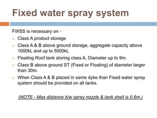
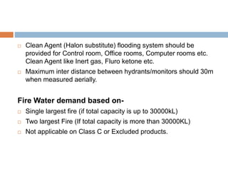
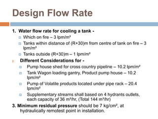
OISD 117
In-short
Introduction –
 This standard lays down the minimum
requirement of fire protection facilities at
Petroleum Depots, Terminals, Pipeline
Installations.
 The petroleum depots, terminals & pipeline/lube
oil installations are generally located in the remote
areas and near railway sidings. However, the
experience shows that with the passage of time,
these get surrounded by residential/industrial
installations. The inventory of flammable materials
stored therein necessitates inbuilt fire protection
facilities.
Fixed water spray system
FWSS is necessary on -
 Class A product storage
 Class A & B above ground storage, aggregate capacity above
1000kL and up to 5000kL
 Floating Roof tank storing class A, Diameter up to 9m.
 Class B above ground ST (Fixed or Floating) of diameter larger
than 30m.
 When Class A & B placed in same dyke than Fixed water spray
system should be provided on all tanks.
(NOTE - Max distance b/w spray nozzle & tank shell is 0.6m.)
 Clean Agent (Halon substitute) flooding system should be
provided for Control room, Office rooms, Computer rooms etc.
Clean Agent like Inert gas, Fluro ketone etc.
 Maximum inter distance between hydrants/monitors should 30m
when measured aerially.
Fire Water demand based on-
 Single largest fire (if total capacity is up to 30000kL)
 Two largest Fire (If total capacity is more than 30000KL)
 Not applicable on Class C or Excluded products.
Design Flow Rate
1. Water flow rate for cooling a tank -
 Which on fire – 3 lpm/m²
 Tanks within distance of (R+30)m from centre of tank on fire – 3
lpm/m²
 Tanks outside (R+30)m – 1 lpm/m²
2. Different Considerations for -
 Pump house shed for cross country pipeline – 10.2 lpm/m²
 Tank Wagon loading gantry, Product pump house – 10.2
lpm/m²
 Pump of Volatile products located under pipe rack – 20.4
lpm/m²
 Supplementary streams shall based on 4 hydrants outlets,
each capacity of 36 m³/hr, (Total 144 m³/hr)
3. Minimum residual pressure should be 7 kg/cm², at
hydraulically remotest point in installation.
Storage
 Effective capacity should for minimum of 4 hours of aggregate
rated capacity of pumps.
 For capacity up to 30000 kL, where reliable water replenishment
@50% or more is available storage capacity can reduced to 3
hours.
 For more than 30000 kL, where reliable water replenishment
@50% or more is available, The Single largest Fire Contingency
shall considered.
 Reservoir shall be in two equal interconnected compartments.
 In case of Steel Tanks, Two Tanks of 50% of required capacity
shall be there.
Fire Water Pumps
 Incase of underground tanks, an overhead tank is required for
flooded suction & accounting leakages.
 Pump shall be capable of discharging 150% of it’s rated
discharge at minimum of 65% rated head.
 If 2 no. of main pumps, at least one stand-by pump should be
installed of same type & capacity for 3 it should 2 stand-by
pumps.
 Fire Pumps should be diesel Engine driven, where main
electricity is reliable 50% can be electricity driven.
 Each engine should have fuel capacity of 6 hours continuous
running.
 Fire Pump installations have at least 30m distance to
Hydrocarbon storage or Potential leak source.
Jockey Pump & Fire line
Jockey Pumps –
 Fire water network shall kept pressurized by jockey pumps.
 Stand-by Jockey pump should provided.
 Capacity should sufficient to maintain pressure in event of
leakage from valves etc.
 Capacity should 5% min and max 10% of design fire rate.
 There should auto cut-in/cut-off should provided.
Fire Water Network –
 Steel pipe should above ground at height of at least 300mm
above or can be underground also.
Hydrants/Monitors
Maximum Inter-distance for–
a. High hazard Area – 30m
b. Non Hazardous Area – 45m
Distance b/w -
a. Tanks/Equipments & Hydrants min 15m from periphery of tank.
b. Distance b/w Monitors & Tanks/Equipments min 15m & max
45m.
Monitors (Water cum Foam)
 Min 2 no. of fixed type HVLR monitors for eac tank farm
containing up to 10000kL capacity of class A product. (Monitors
should placed in opposite direction).
 For more than 10000 kL of class A product, additional monitors
of having foam flow rate of 8.1 lpm/m², should installed such a
way each tank within coverage of 2 monitors.
 For B & C class Products (in Tank Farm) min 1 no. of trolley
mounted mobile type W/F monitor.
 TW/TT loading facilities should have alternative hydrant & W/F
monitor at a spacing of 30m on both sides of gantry.
 Hydrant isolation valve situated at workable height of 1.2m
above ground.
Foam Conveying System
Types –
a. Fixed foam conveying system
b. Semi-fixed foam conveying system
c. Mobile foam conveying system
d. Sub-surface foam injection
e. Under the seal Foam Protection
For Fixed Roof Tank Protection –
Tank
Dia
(m)
18-20 20-25 25-30 30-35 35-40 40-45 45-50
Foam
Pourer
no.
2 3 4 5 6 8 10
Protection for Dyke area / Spill
Fire
 Medium expansion foam generator for –
a. Class A tanks – 2 no. fixed for each tank dyke
b. Class B tanks – 2 no. portable for each location
 Foam Application Rate for –
a. Cone roof containing HC products – 5 lpm/m²
b. Floating roof – 12 lpm/m²
c. Floating roof in case of roof sinking – 8.1 lpm/m²
 Duration for Foam Discharge –
a. Tanks containing A & B – 65 minutes
b. Primariy spill fire protection – 30 minutes
Hoses & Nozzles
Hoses –
 MOC – Reinforced rubber lined canvas or Non-percolating
Synthetic as per IS 636/UL 19.
 Standard for – (a) length – 15m (b) diameter – 63mm
 No. of hoses stored in Oil installation shall be 30% no. of
hydrants outlets.
 In any case hoses shall not be less than 10.
Nozzle –
 Types – Jet nozzle, Fog nozzle, Universal nozzle, Water curtain
nozzle, Jet Branch pipe & Fog Branch pipe.
 Jet nozzle should be in each Hose box.
Fire Alarm System
 Fire – 2 mins wailing sound.
 Disaster – 2 mins wailing sound repeated thrice with gap of 10
secs.
 All Clear – 2 mins straight run sound.
 Test Run – 2 mins straight run sound.
Fire Protection system
Inspection & Maintenance
Pump –
 Test Run – Twice a week for Half an hour.
 Checking, Testing & Shut-off pressure observing once in 6 months.
 Each pump run continuously 4 hours for test run, once a year.
 If stand-by Jockey pump provided, Check it weekly.
Fire Water Ring Main –
 Ring main should check for all leak once in 6 months.
 Ring main line & it’s all accessories (Valves, hydrants, monitors etc)
should checked for (damage, corrosion, defects etc) every month.
Hoses – Once in 6 months, Hydraulically testing.
Siren – Once a week.
Extinguishers – as per OISD – 142.
Fire Protection system
Inspection & Maintenance
Fire Water Spray System –
 Test for effectiveness & coverage once in 6 months.
 Spray nozzle inspection for proper orientation, corrosion,
cleaning at least once a year (if necessary).
 Strainers provided, shall be cleaned once in a quarter & logged.
Fixed/Semi-fixed foam system –
 On Storage Tanks should be tested once in 6 months.
Clean Agent System –
 Checked once every 6 months.
 Fully inspected for proper orientation once every year.
Wheeled Fire Fighting
Equipments
Water cum Foam Monitors –
 For tanks larger than 9m dia -
Foam Compound Trolley –
 Capacity of 200/210 liters -
Size of Terminal W/F Monitors
Up to 1000 kL NIL
Up to 10,000 kL Min 2 no.s of 1000
GPM each
More than 10,000 kL More than 2 no.s of
1000 GPM each.
Tank Dia
(m)
Foam
Trolley
Up to 24 m 1 no.
24 to 30 m 2 no.
Above 30 m 3 no.
Fire Extinguishers
 While selecting, these factors should be considered as flow rate,
discharge time, & throw in line as per IS 2190/UL 711.
 While selecting DCP, due consideration as –
a. Apparent density (0.65 ±0.05)
b. Fire Rating (144B)
c. Thermal gravimetric analysis & Foam compatibility.
d. Siliconised Potassium Bicarbonate (IS4308)/ Mono Ammonium
Phosphate (IS4605) can also be used as DCP.
 Spare CO2 cartridge & DCP refills, min 10% of total charge in
extinguishers should be maintained at location.
 Sand buckets should round bottom & bottom handle, having 9 liters
water capacity (IS 2546) & free from oil, water & rubbish.
 The max running distance to locate an extinguisher shall not exceed
15m.
 Extinguisher’s top surface should not more than 1.5m above from
ground.
 Rain protection should provided for Fire Extinguishers & Sand
Chemical Foam -
• Generally used in fire extinguishers.
• Most common ingredients as Sodium Bicarbonate & Aluminum
Sulphate with Stabilizer.
FIRE FIGHTING
FOAM
Foam types /
Parameters
Low Expansion Medium
Expansion
High Expansion
Expansion
ratio
Up to 50:1 Up to 51:1 to 500:1 Up to 501:1 to
1500:1
Produced by Self aspirating foam
branch pipes.
Self aspirating Foam
branch pipes with
nets.
Typically produced
by foam generators
with air fans.
Characteristic
s
More water & better
resistant to Fire
Poor Cooling, Poor
resistant to hot
surfaces / radiant
heat
Poor Cooling, Poor
resistant to hot
surfaces / radiant
heat
Usage Used in Oil refinery
and installations
Limited use in
controlling
Hydrocarbon liquid
fires.
Very limited use, but
used for protection
of hydrocarbon
gases stored under
cryogenic conditions
& for warehouse
Foam /
parameter
s
Protein
Foam
Fluro
Protein
Foam
Aqueos
Film
Forming
Foam
Multipurpo
se AFFF
Film
Forming
FPF
Consists
of
Hydrolyzed
Protein
(From
animals /
vegetables)
Fluro
Chemical
Fluro Carbon
Surfactants,
Foaming
agents
Synthetic
foaming
liquid
Combination
of AFFF &
Fluro Protein
Foam
Inductio
n Rate
3 to 6 % 3 to 6 % 3 to 6 % 3 % for
Hydrocarbon
liquid & 5 %
for water
miscible
solvents
3 to 6 %
Shelf
Life
2 years 2 years More than
10 years
Not less than
10 years
5 years
Medium & High Expansion
Foams
 Synthetic foam concentrate used with suitable
device.
 This can be used on Hydrocarbon fuels of low
boiling point.
 Foam is very light weight & gives poor cooling effect
compare to Low expansion foam.
 Induction Rate in Water vary from 1.5 % to 3 %.
 Many low expansion foam also used to produced
Medium/High Expansion foam.
 These foams susceptible to easy breakdown by hot
fuel layers & radiant heat.
 Thank You !

OISD STD 117.pptx

  • 1.
  • 2.
    Introduction –  Thisstandard lays down the minimum requirement of fire protection facilities at Petroleum Depots, Terminals, Pipeline Installations.  The petroleum depots, terminals & pipeline/lube oil installations are generally located in the remote areas and near railway sidings. However, the experience shows that with the passage of time, these get surrounded by residential/industrial installations. The inventory of flammable materials stored therein necessitates inbuilt fire protection facilities.
  • 3.
    Fixed water spraysystem FWSS is necessary on -  Class A product storage  Class A & B above ground storage, aggregate capacity above 1000kL and up to 5000kL  Floating Roof tank storing class A, Diameter up to 9m.  Class B above ground ST (Fixed or Floating) of diameter larger than 30m.  When Class A & B placed in same dyke than Fixed water spray system should be provided on all tanks. (NOTE - Max distance b/w spray nozzle & tank shell is 0.6m.)
  • 4.
     Clean Agent(Halon substitute) flooding system should be provided for Control room, Office rooms, Computer rooms etc. Clean Agent like Inert gas, Fluro ketone etc.  Maximum inter distance between hydrants/monitors should 30m when measured aerially. Fire Water demand based on-  Single largest fire (if total capacity is up to 30000kL)  Two largest Fire (If total capacity is more than 30000KL)  Not applicable on Class C or Excluded products.
  • 5.
    Design Flow Rate 1.Water flow rate for cooling a tank -  Which on fire – 3 lpm/m²  Tanks within distance of (R+30)m from centre of tank on fire – 3 lpm/m²  Tanks outside (R+30)m – 1 lpm/m² 2. Different Considerations for -  Pump house shed for cross country pipeline – 10.2 lpm/m²  Tank Wagon loading gantry, Product pump house – 10.2 lpm/m²  Pump of Volatile products located under pipe rack – 20.4 lpm/m²  Supplementary streams shall based on 4 hydrants outlets, each capacity of 36 m³/hr, (Total 144 m³/hr) 3. Minimum residual pressure should be 7 kg/cm², at hydraulically remotest point in installation.
  • 6.
    Storage  Effective capacityshould for minimum of 4 hours of aggregate rated capacity of pumps.  For capacity up to 30000 kL, where reliable water replenishment @50% or more is available storage capacity can reduced to 3 hours.  For more than 30000 kL, where reliable water replenishment @50% or more is available, The Single largest Fire Contingency shall considered.  Reservoir shall be in two equal interconnected compartments.  In case of Steel Tanks, Two Tanks of 50% of required capacity shall be there.
  • 7.
    Fire Water Pumps Incase of underground tanks, an overhead tank is required for flooded suction & accounting leakages.  Pump shall be capable of discharging 150% of it’s rated discharge at minimum of 65% rated head.  If 2 no. of main pumps, at least one stand-by pump should be installed of same type & capacity for 3 it should 2 stand-by pumps.  Fire Pumps should be diesel Engine driven, where main electricity is reliable 50% can be electricity driven.  Each engine should have fuel capacity of 6 hours continuous running.  Fire Pump installations have at least 30m distance to Hydrocarbon storage or Potential leak source.
  • 8.
    Jockey Pump &Fire line Jockey Pumps –  Fire water network shall kept pressurized by jockey pumps.  Stand-by Jockey pump should provided.  Capacity should sufficient to maintain pressure in event of leakage from valves etc.  Capacity should 5% min and max 10% of design fire rate.  There should auto cut-in/cut-off should provided. Fire Water Network –  Steel pipe should above ground at height of at least 300mm above or can be underground also.
  • 9.
    Hydrants/Monitors Maximum Inter-distance for– a.High hazard Area – 30m b. Non Hazardous Area – 45m Distance b/w - a. Tanks/Equipments & Hydrants min 15m from periphery of tank. b. Distance b/w Monitors & Tanks/Equipments min 15m & max 45m.
  • 10.
    Monitors (Water cumFoam)  Min 2 no. of fixed type HVLR monitors for eac tank farm containing up to 10000kL capacity of class A product. (Monitors should placed in opposite direction).  For more than 10000 kL of class A product, additional monitors of having foam flow rate of 8.1 lpm/m², should installed such a way each tank within coverage of 2 monitors.  For B & C class Products (in Tank Farm) min 1 no. of trolley mounted mobile type W/F monitor.  TW/TT loading facilities should have alternative hydrant & W/F monitor at a spacing of 30m on both sides of gantry.  Hydrant isolation valve situated at workable height of 1.2m above ground.
  • 11.
    Foam Conveying System Types– a. Fixed foam conveying system b. Semi-fixed foam conveying system c. Mobile foam conveying system d. Sub-surface foam injection e. Under the seal Foam Protection For Fixed Roof Tank Protection – Tank Dia (m) 18-20 20-25 25-30 30-35 35-40 40-45 45-50 Foam Pourer no. 2 3 4 5 6 8 10
  • 12.
    Protection for Dykearea / Spill Fire  Medium expansion foam generator for – a. Class A tanks – 2 no. fixed for each tank dyke b. Class B tanks – 2 no. portable for each location  Foam Application Rate for – a. Cone roof containing HC products – 5 lpm/m² b. Floating roof – 12 lpm/m² c. Floating roof in case of roof sinking – 8.1 lpm/m²  Duration for Foam Discharge – a. Tanks containing A & B – 65 minutes b. Primariy spill fire protection – 30 minutes
  • 13.
    Hoses & Nozzles Hoses–  MOC – Reinforced rubber lined canvas or Non-percolating Synthetic as per IS 636/UL 19.  Standard for – (a) length – 15m (b) diameter – 63mm  No. of hoses stored in Oil installation shall be 30% no. of hydrants outlets.  In any case hoses shall not be less than 10. Nozzle –  Types – Jet nozzle, Fog nozzle, Universal nozzle, Water curtain nozzle, Jet Branch pipe & Fog Branch pipe.  Jet nozzle should be in each Hose box.
  • 14.
    Fire Alarm System Fire – 2 mins wailing sound.  Disaster – 2 mins wailing sound repeated thrice with gap of 10 secs.  All Clear – 2 mins straight run sound.  Test Run – 2 mins straight run sound.
  • 15.
    Fire Protection system Inspection& Maintenance Pump –  Test Run – Twice a week for Half an hour.  Checking, Testing & Shut-off pressure observing once in 6 months.  Each pump run continuously 4 hours for test run, once a year.  If stand-by Jockey pump provided, Check it weekly. Fire Water Ring Main –  Ring main should check for all leak once in 6 months.  Ring main line & it’s all accessories (Valves, hydrants, monitors etc) should checked for (damage, corrosion, defects etc) every month. Hoses – Once in 6 months, Hydraulically testing. Siren – Once a week. Extinguishers – as per OISD – 142.
  • 16.
    Fire Protection system Inspection& Maintenance Fire Water Spray System –  Test for effectiveness & coverage once in 6 months.  Spray nozzle inspection for proper orientation, corrosion, cleaning at least once a year (if necessary).  Strainers provided, shall be cleaned once in a quarter & logged. Fixed/Semi-fixed foam system –  On Storage Tanks should be tested once in 6 months. Clean Agent System –  Checked once every 6 months.  Fully inspected for proper orientation once every year.
  • 17.
    Wheeled Fire Fighting Equipments Watercum Foam Monitors –  For tanks larger than 9m dia - Foam Compound Trolley –  Capacity of 200/210 liters - Size of Terminal W/F Monitors Up to 1000 kL NIL Up to 10,000 kL Min 2 no.s of 1000 GPM each More than 10,000 kL More than 2 no.s of 1000 GPM each. Tank Dia (m) Foam Trolley Up to 24 m 1 no. 24 to 30 m 2 no. Above 30 m 3 no.
  • 18.
    Fire Extinguishers  Whileselecting, these factors should be considered as flow rate, discharge time, & throw in line as per IS 2190/UL 711.  While selecting DCP, due consideration as – a. Apparent density (0.65 ±0.05) b. Fire Rating (144B) c. Thermal gravimetric analysis & Foam compatibility. d. Siliconised Potassium Bicarbonate (IS4308)/ Mono Ammonium Phosphate (IS4605) can also be used as DCP.  Spare CO2 cartridge & DCP refills, min 10% of total charge in extinguishers should be maintained at location.  Sand buckets should round bottom & bottom handle, having 9 liters water capacity (IS 2546) & free from oil, water & rubbish.  The max running distance to locate an extinguisher shall not exceed 15m.  Extinguisher’s top surface should not more than 1.5m above from ground.  Rain protection should provided for Fire Extinguishers & Sand
  • 19.
    Chemical Foam - •Generally used in fire extinguishers. • Most common ingredients as Sodium Bicarbonate & Aluminum Sulphate with Stabilizer. FIRE FIGHTING FOAM
  • 20.
    Foam types / Parameters LowExpansion Medium Expansion High Expansion Expansion ratio Up to 50:1 Up to 51:1 to 500:1 Up to 501:1 to 1500:1 Produced by Self aspirating foam branch pipes. Self aspirating Foam branch pipes with nets. Typically produced by foam generators with air fans. Characteristic s More water & better resistant to Fire Poor Cooling, Poor resistant to hot surfaces / radiant heat Poor Cooling, Poor resistant to hot surfaces / radiant heat Usage Used in Oil refinery and installations Limited use in controlling Hydrocarbon liquid fires. Very limited use, but used for protection of hydrocarbon gases stored under cryogenic conditions & for warehouse
  • 21.
    Foam / parameter s Protein Foam Fluro Protein Foam Aqueos Film Forming Foam Multipurpo se AFFF Film Forming FPF Consists of Hydrolyzed Protein (From animals/ vegetables) Fluro Chemical Fluro Carbon Surfactants, Foaming agents Synthetic foaming liquid Combination of AFFF & Fluro Protein Foam Inductio n Rate 3 to 6 % 3 to 6 % 3 to 6 % 3 % for Hydrocarbon liquid & 5 % for water miscible solvents 3 to 6 % Shelf Life 2 years 2 years More than 10 years Not less than 10 years 5 years
  • 22.
    Medium & HighExpansion Foams  Synthetic foam concentrate used with suitable device.  This can be used on Hydrocarbon fuels of low boiling point.  Foam is very light weight & gives poor cooling effect compare to Low expansion foam.  Induction Rate in Water vary from 1.5 % to 3 %.  Many low expansion foam also used to produced Medium/High Expansion foam.  These foams susceptible to easy breakdown by hot fuel layers & radiant heat.
  • 23.