Downloaded 173 times


![7
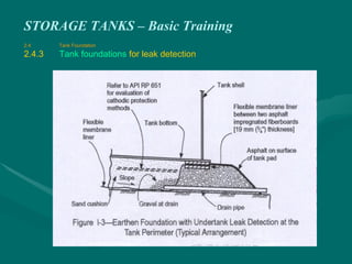
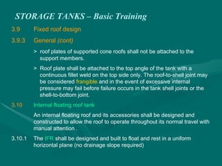
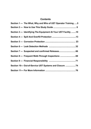
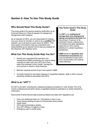
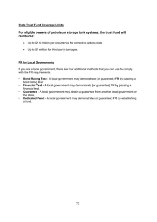
2 Tank Gauging techniques
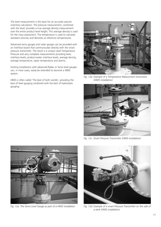
Tank gauging has a long history! Since each user and every
application has its own specific requirements, several
measurement techniques and solutions to gauge tank contents
are currently available.
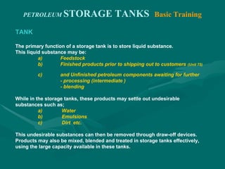
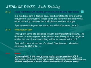
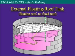
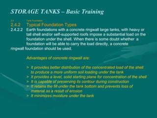
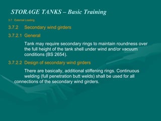
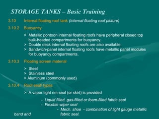
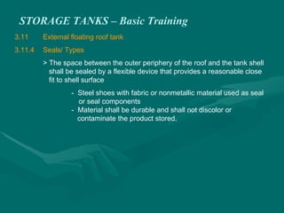
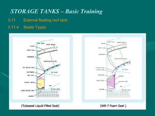
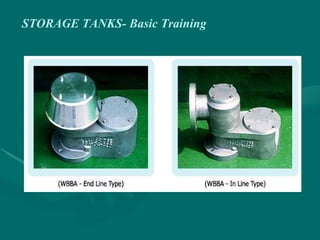
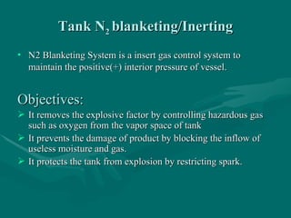
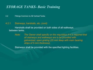
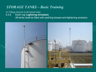
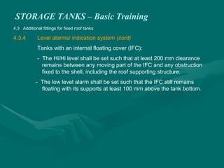
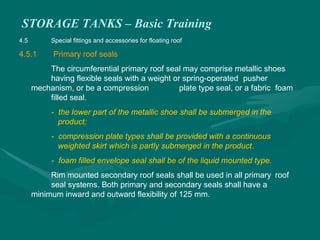
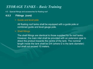
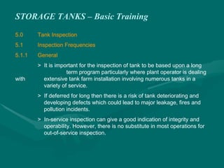
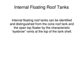
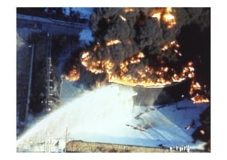
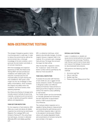
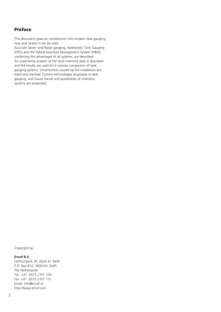
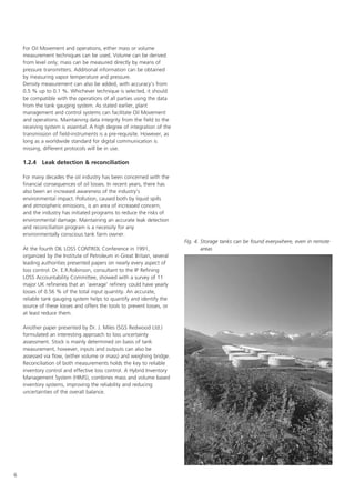
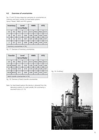
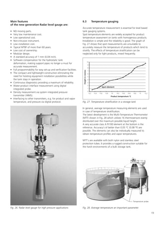
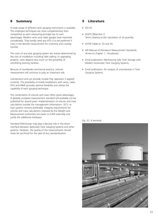
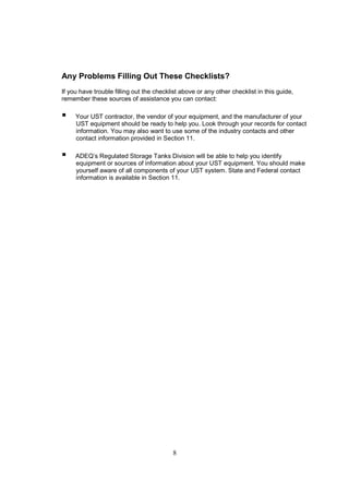
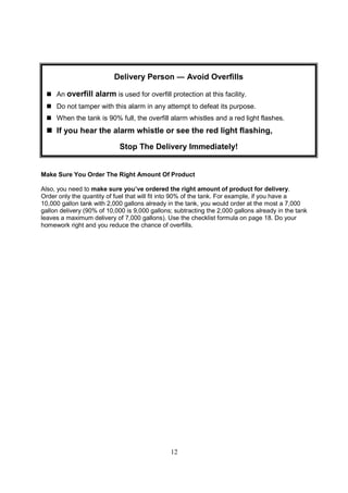
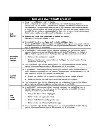
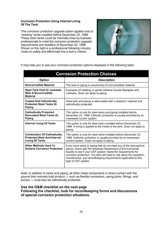
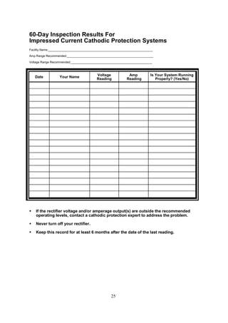
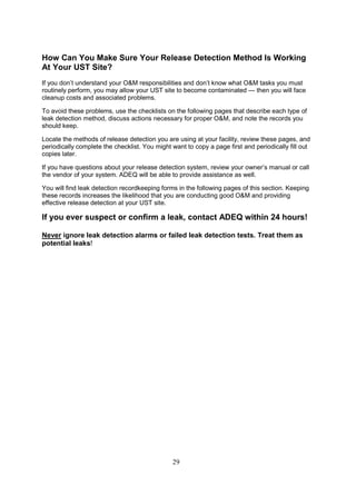
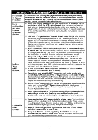
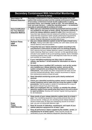
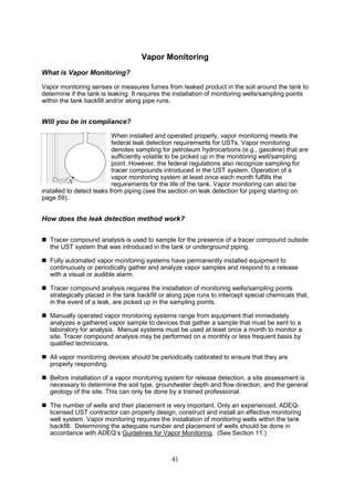
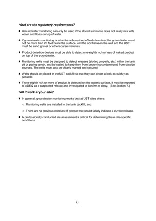
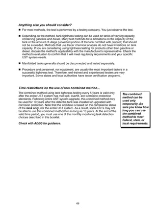
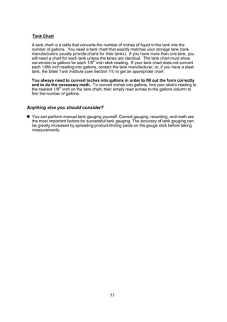
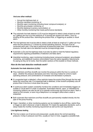
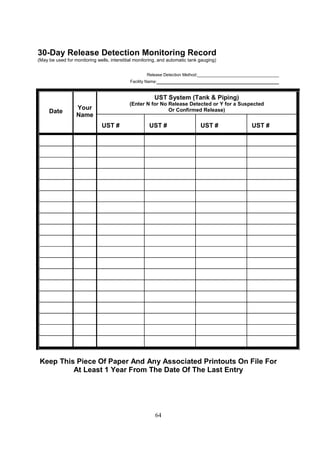
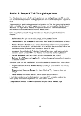
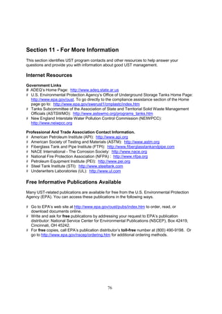
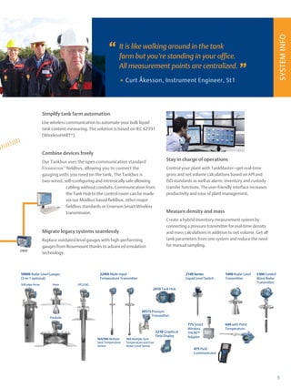
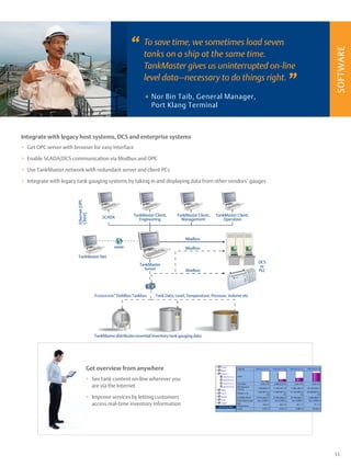
2.1 Manual gauging
Tank gauging started with manual gauging, (Fig. 5) using a
graduated diptape or dipstick. This technique is still used
worldwide, and is today still the verification for gauge
performance calibration and verification.
The typical accuracy of a diptape used for custody transfer
measurements is often specified as ± (0.1 + 0.1 L) mm
[equal to ± (0.004 + 0.0012L') inch] for the initial calibration of
new dip tapes. In the metric formula L is the level in meters and
in the ft and inch formula L' is the level in ft. For tapes in use,
the recalibration accuracy applies. This accuracy is twice the
uncertainty of a new tape. But the tape uncertainty is not the
only cause of error. Accurate hand dipping is a difficult task,
particularly with high winds, cold weather, during night time or
when special protection equipment has to be used.
Additionally, a human error, of at least ± 2 mm (± 0.08 inch),
has to be added to the tape readings. API Standard 2545 is
dedicated completely to manual tank gauging.
Another disadvantage of manual tank gauging is that
employees are often not allowed to be on a tank because of
safety regulations, resulting in costly, long waiting times.
2.2 Float and tape gauges
The first float and tape gauges, also called Automatic Tank
Gauges, were introduced around 1930. These instruments use
a large, heavy float in order to obtain sufficient driving force.
Initially the float was connected via a cable to a balance weight
with a scale and pointer along the tank shell indicating the
level. Newer versions had the float connected, via a perforated
steel tape, to a constant torque spring motor.
The perforations drive a simple mechanical counter which acts
as local indicator. Typical accuracy of a mechanical gauge is in
the range of 10 mm (½ inch). Due to the mechanical friction in
pulleys, spring motor and indicator, the reliability is poor.
Remote indication is possible via an electronic transmitter
coupled to the indicator. However, this will not improve the
reliability or accuracy of the mechanical gauge.
One of the major disadvantages with float driven instruments is
the continuous sudden movement due to the turbulence of the
liquid gauged. These movements, which can be rather violent,
cause a continuous acceleration and deceleration of the drive
mechanism, resulting in excessive wear and tear of the local
indicator, transmitter and other devices coupled to the gauge.
The reversing motions and accelerations cannot be followed by
the indicating system and transmitter. Often the gear mecha-
nism, driving the indicator and transmitter shaft, disengages,
resulting in erroneous readings and de-synchronization of the
transmitter. This leads to a considerable maintenance and lack
of measurement reliability. In light of the present worldwide
concern to prevent product spills, these gauges should no
longer be used. Because of their low price, however, a large
share of the world's tanks are still equipped with these
instruments.
2.3 Servo gauges
Servo tank gauges (Fig. 7) are a considerable improvement over
the float driven instruments. They were developed during the
1950s. In this gauge, the float is replaced by a small displacer,
suspended by a strong, flexible measuring wire. Instead of a
spring-motor, servo gauges use an electrical servo motor to
raise and lower the displacer. An ingenious weighing system
continuously measures the weight and buoyancy of the
Fig. 6. Float and tape
gauge
Fig. 5. Manual Gauging](https://image.slidesharecdn.com/storagetank-230225213205-798404d2/85/Storage-Tank-pdf-149-320.jpg)
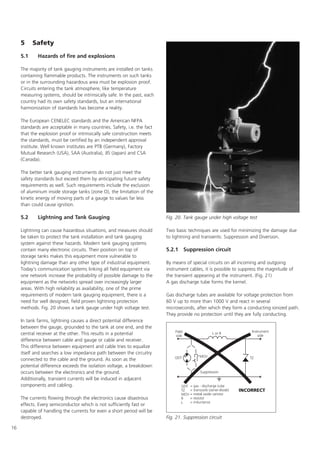

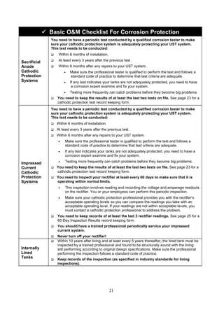
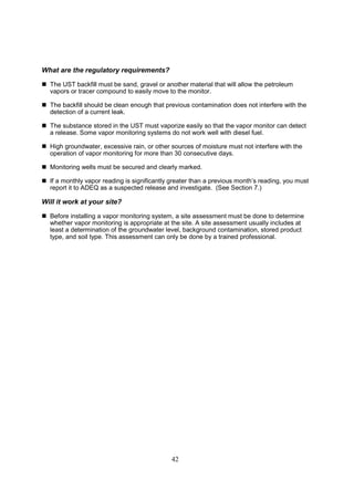
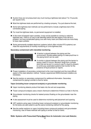
![51
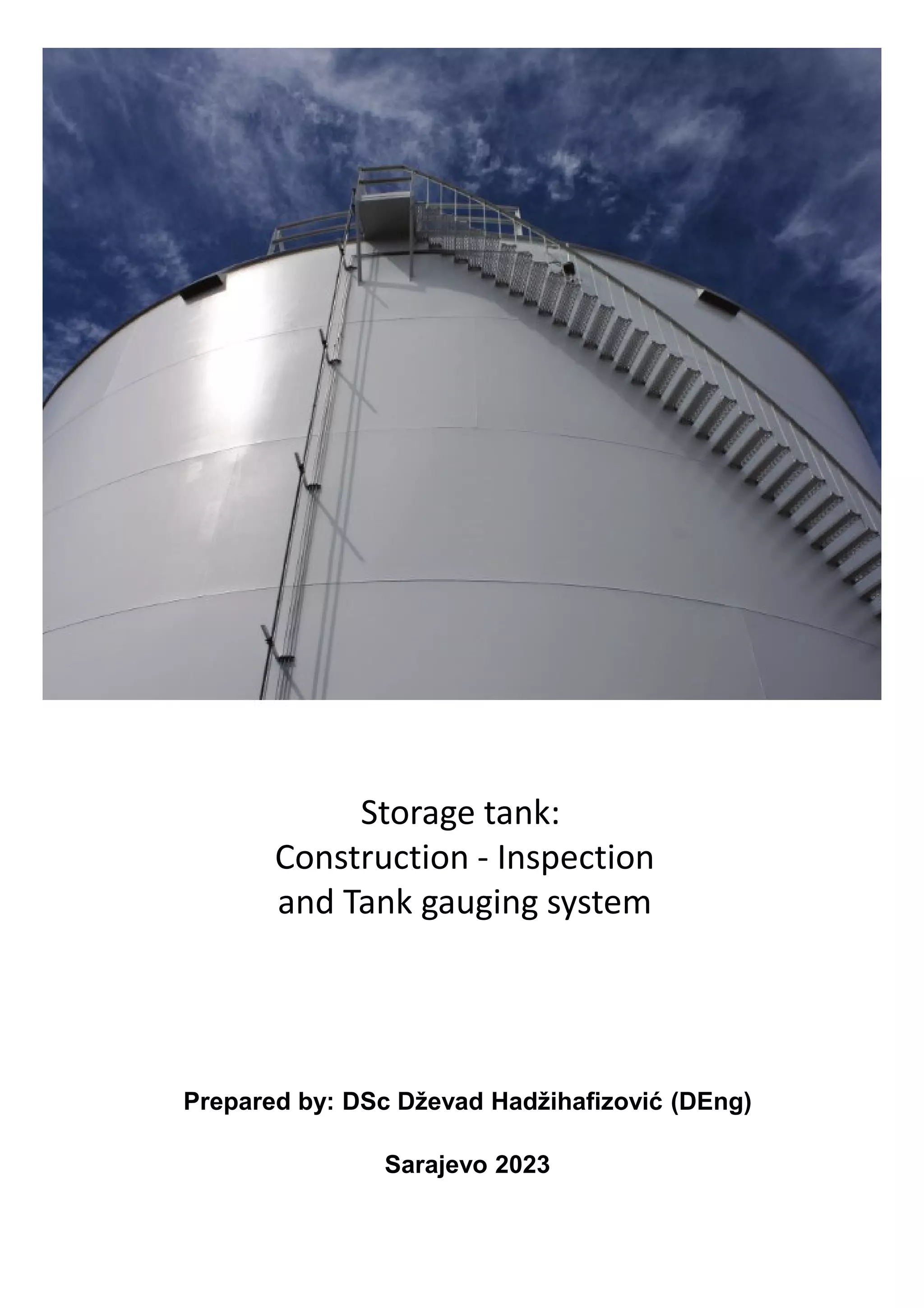
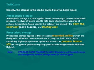
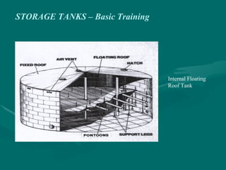
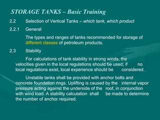
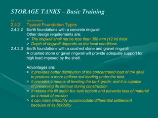
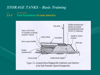
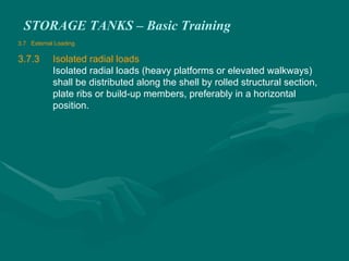
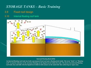
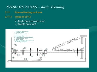
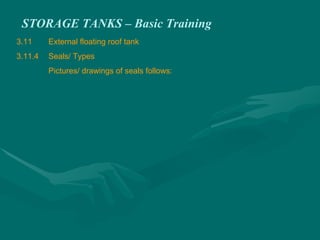
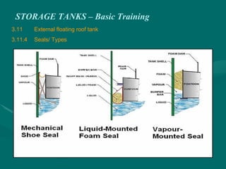
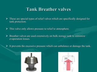
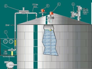
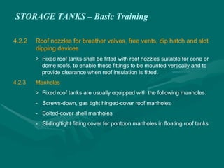
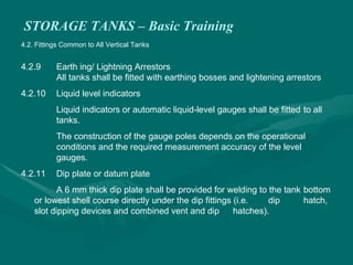
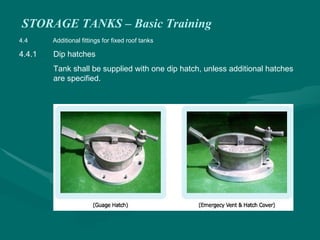
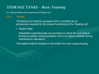
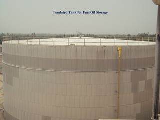
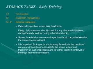
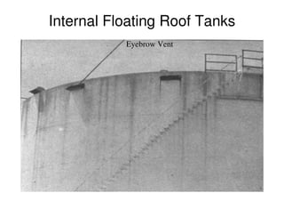
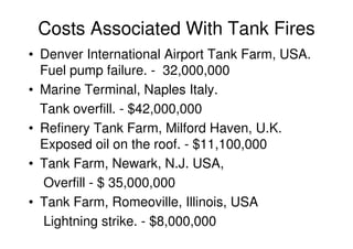
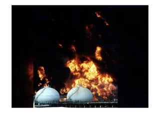
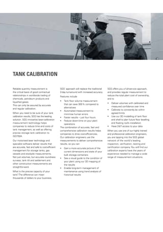
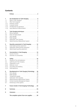
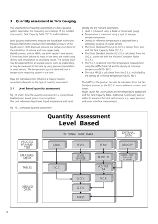
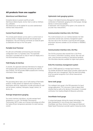
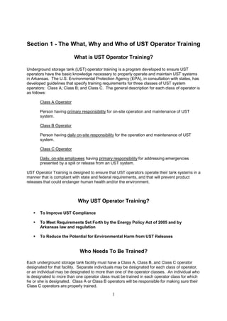
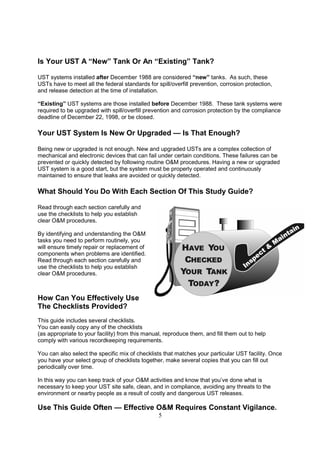
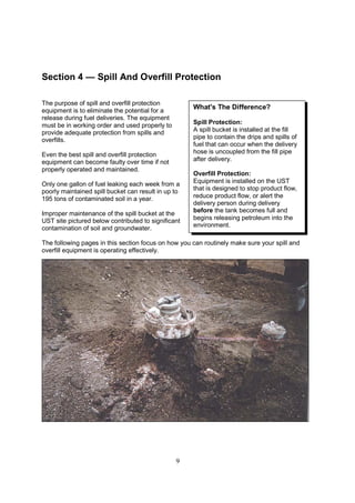
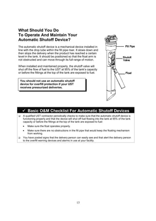
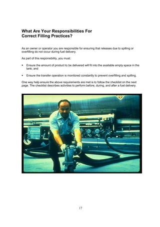
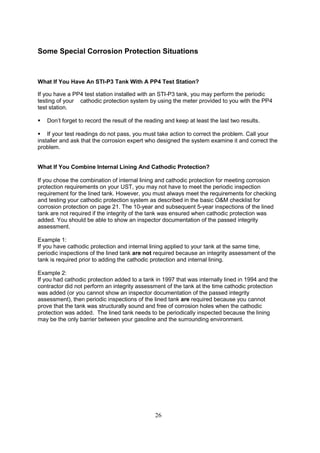
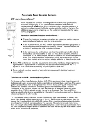
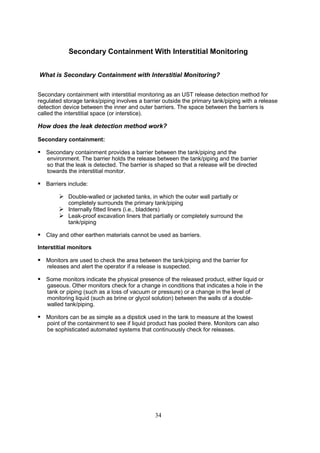
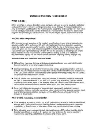
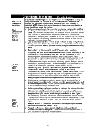
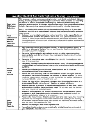
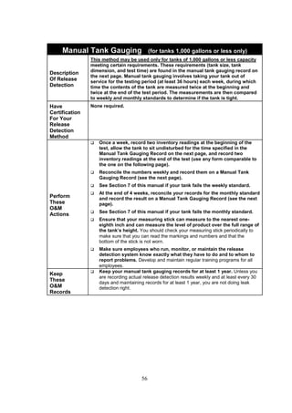
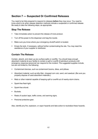
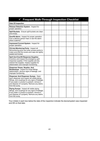
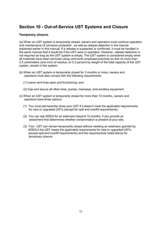
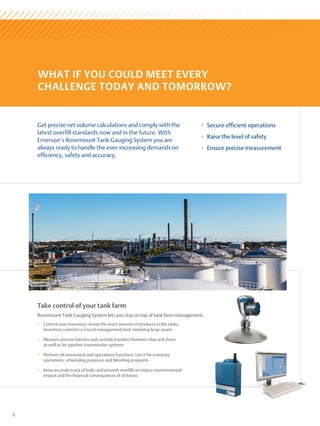
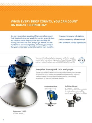
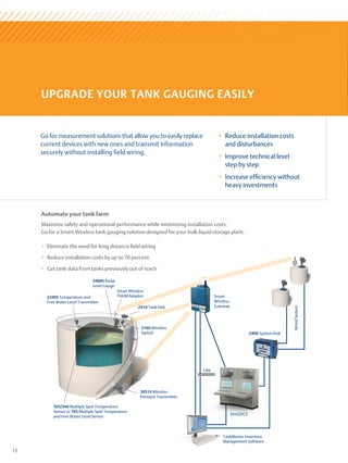
Daily Inventory Worksheet
Facility Name: _________________________________________
Your Name: _________________________________________
Date: _________________________________________
Tank Identification
Type Of Fuel
Tank Size In Gallons
End Stick Inches
Amount Pumped
Totalizer Reading
Totalizer Reading
Totalizer Reading
Totalizer Reading
Totalizer Reading
Totalizer Reading
Totalizer Reading
Totalizer Reading
Today's Sum Of Totalizers
Previous Day's Sum Of
Totalizers
Amount Pumped Today
Delivery Record
Inches of Fuel Before Delivery
Gallons of Fuel Before
Delivery
(from tank chart)
Inches of Fuel After Delivery
Gallons of Fuel After Delivery
(from tank chart)
Gallons Delivered (Stick)
[Gallons After ! Gallons Before]
Gross Gallons Delivered
(Receipt)](https://image.slidesharecdn.com/storagetank-230225213205-798404d2/85/Storage-Tank-pdf-220-320.jpg)
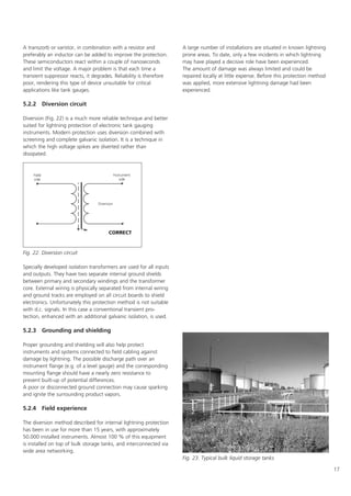
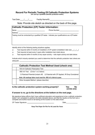
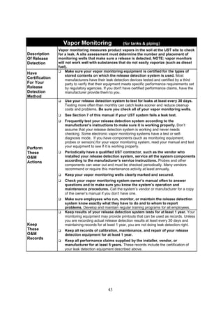
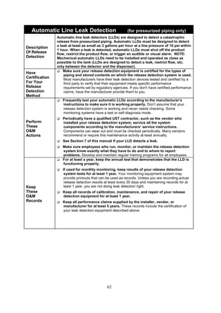
![52
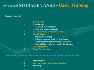
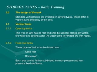
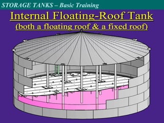
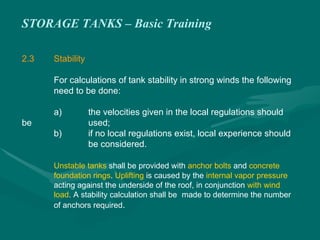
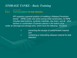
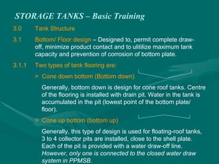
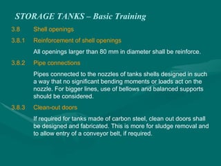
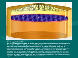
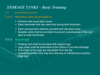
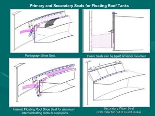
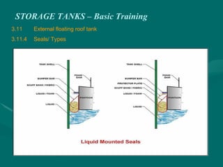
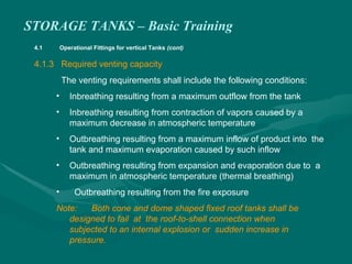
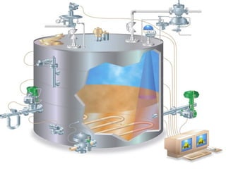
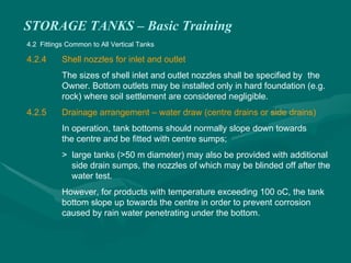
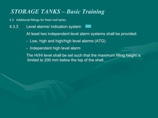
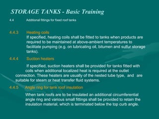
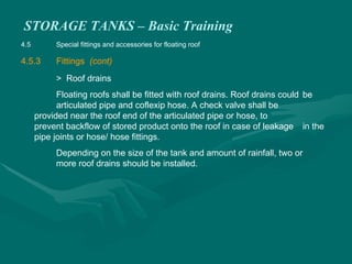
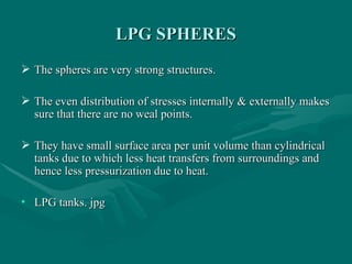
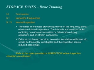
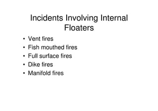
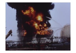
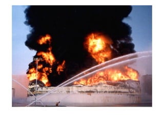
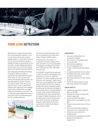
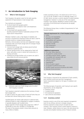
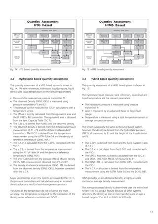
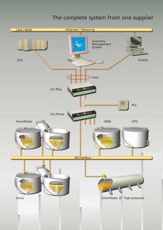
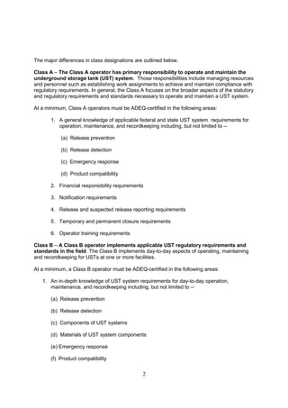
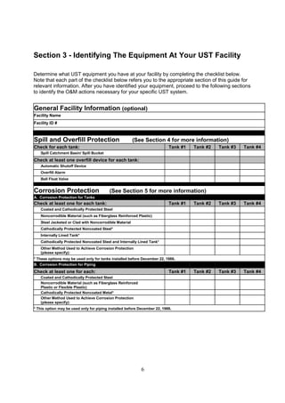
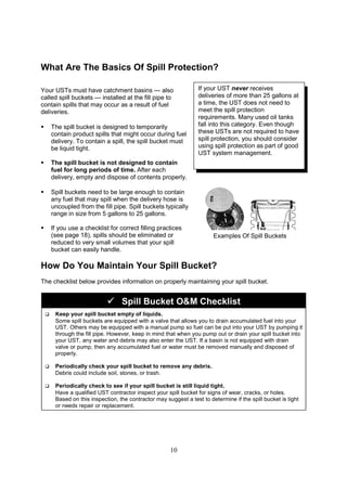
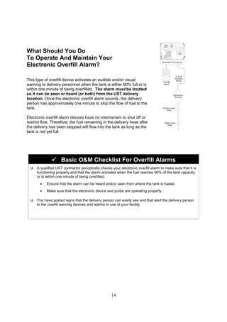
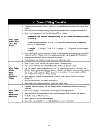
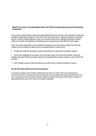
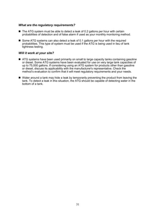
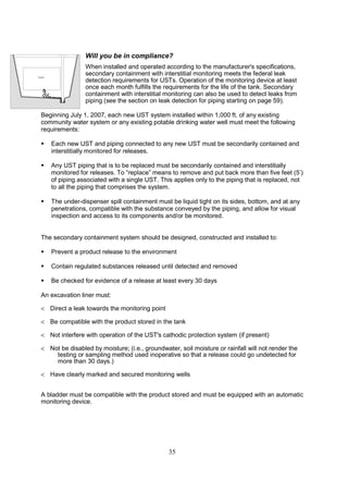
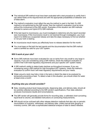
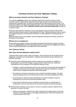
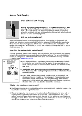
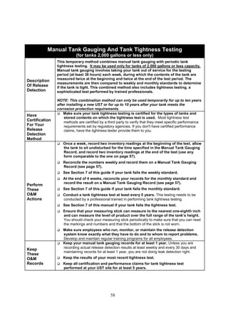
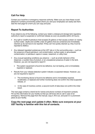
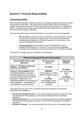
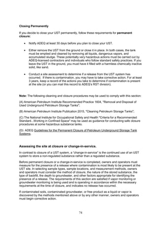
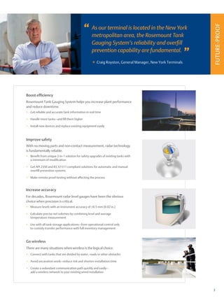
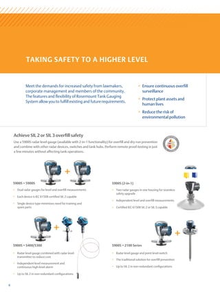
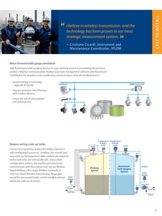
Monthly Inventory Record
Month/Year :_______/______ Tank Identification Type Of Fuel:____________________________
Facility Name:_________________________________________________
Date Of Water Check: ________ Level Of Water (Inches):______
Date
Start Stick
Inventory
(Gallons)
Gallons
Delivered
Gallons
Pumped
Book
Inventory
(Gallons)
End Stick Inventory
(Inches) (Gallons)
Daily Over (+) Or
Short (–)
[End – Book]
Initials
1 (+) (-) (=)
2 (+) (-) (=)
3 (+) (-) (=)
4 (+) (-) (=)
5 (+) (-) (=)
6 (+) (-) (=)
7 (+) (-) (=)
8 (+) (-) (=)
9 (+) (-) (=)
7 (+) (-) (=)
8 (+) (-) (=)
9 (+) (-) (=)
10 (+) (-) (=)
11 (+) (-) (=)
12 (+) (-) (=)
13 (+) (-) (=)
14 (+) (-) (=)
15 (+) (-) (=)
16 (+) (-) (=)
17 (+) (-) (=)
18 (+) (-) (=)
19 (+) (-) (=)
20 (+) (-) (=)
21 (+) (-) (=)
22 (+) (-) (=)
23 (+) (-) (=)
24 (+) (-) (=)
25 (+) (-) (=)
26 (+) (-) (=)
27 (+) (-) (=)
28 (+) (-) (=)
29 (+) (-) (=)
30 (+) (-) (=)
31 (+) (-) (=)
Total Gallons Pumped Total Gallons Over Or Short
Leak Check: Compare these numbers
Drop the last two digits
from the Total Gallons
Pumped number and enter here: _____________ + 130 = ____________ gallons
Is the total gallons over or short larger than leak check result? Yes No (circle one)
If your answer is “Yes” for 2 months in a row, notify the regulatory agency as soon as possible. (Keep this
piece of paper on file for at least 1 year)](https://image.slidesharecdn.com/storagetank-230225213205-798404d2/85/Storage-Tank-pdf-221-320.jpg)
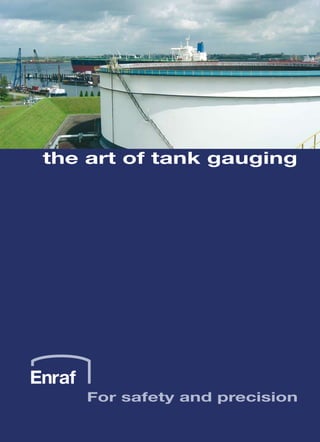
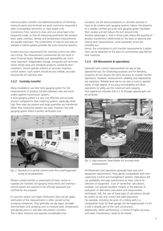
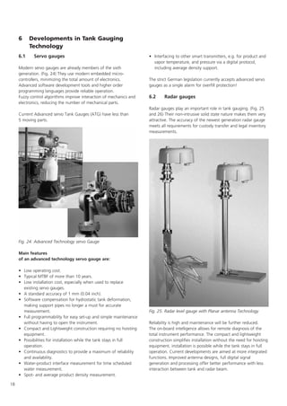
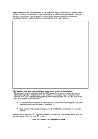
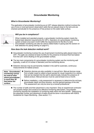
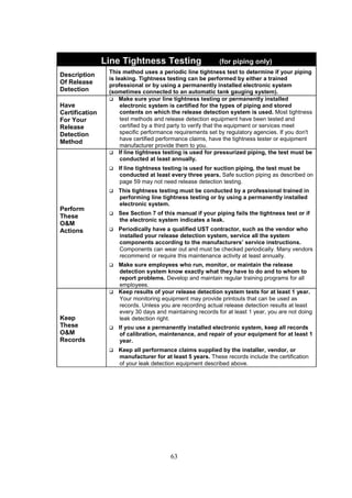
![57
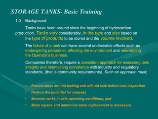
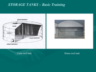
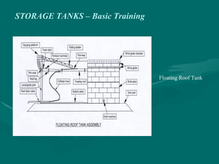
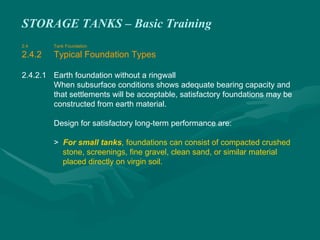
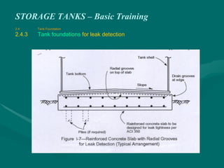
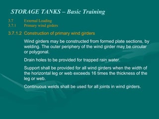
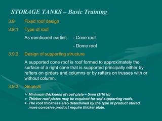
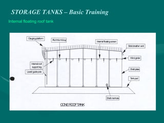
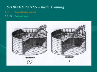
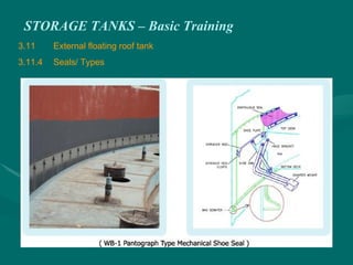
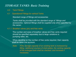
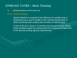
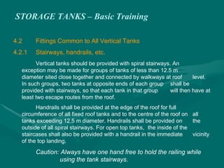
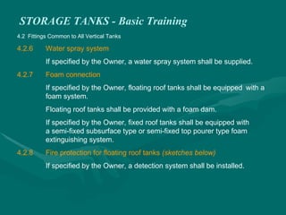
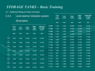
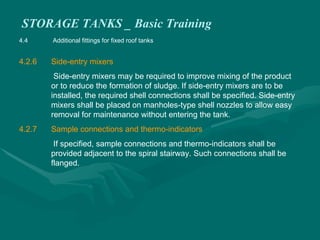
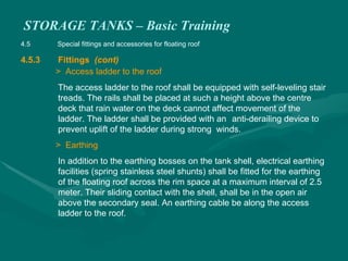
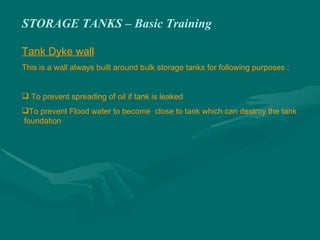
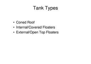
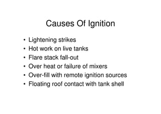
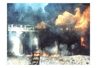
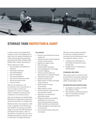
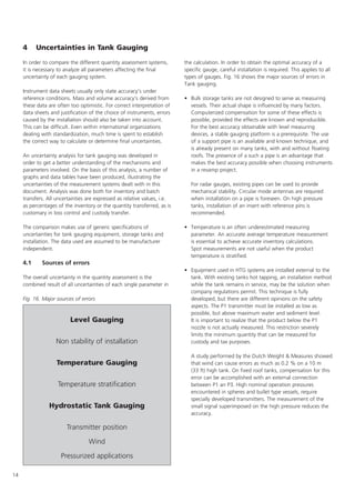
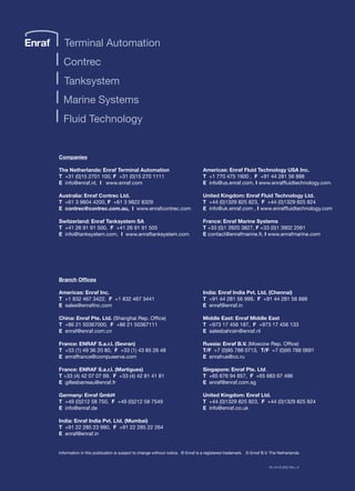
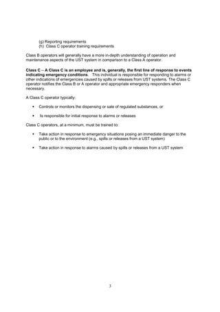
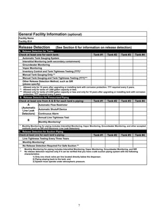
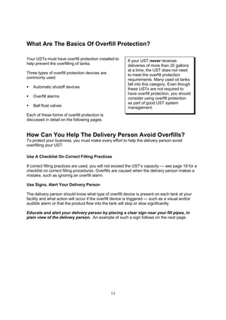
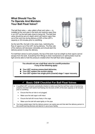
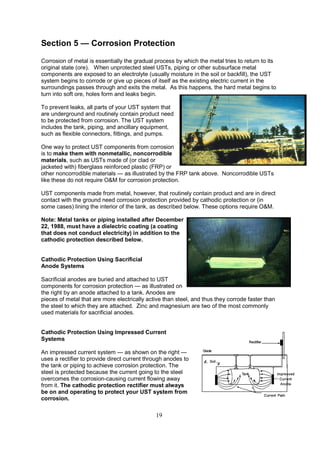
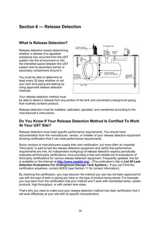
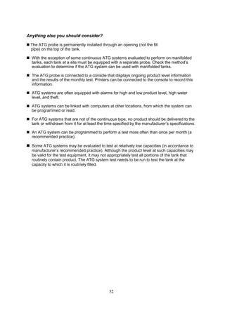
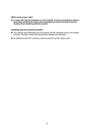
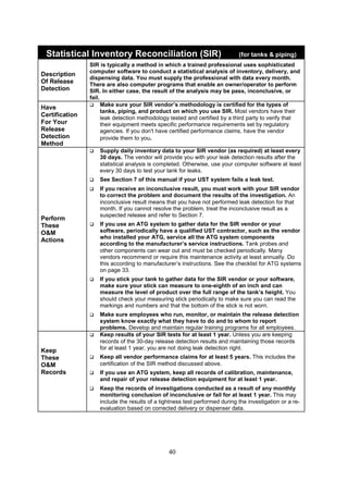
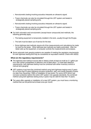
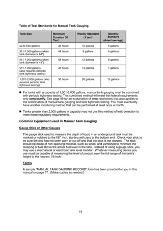
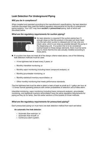
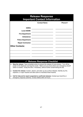
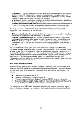
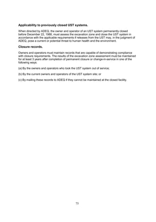
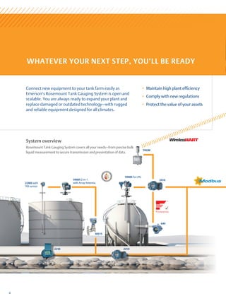
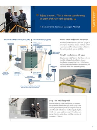
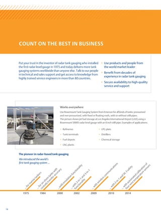
Compare your weekly readings and the
monthly average of the 4
weekly readings with the standards
shown in the table on the left.
If the calculated change exceeds the
weekly standard, the UST may
be leaking. Also, the monthly average
of the 4 weekly test results
must be compared to the monthly
standard in the same way.
If either the weekly or the monthly
standards have been exceeded, the
UST may be leaking. Call ADEQ within 24 to report the suspected release
and get further instructions.
Start Test
(month,
day, and
time)
First
Initial
Stick
Reading
Second
Initial
Stick
Reading
Average
Initial
Reading
Initial
Gallons
(convert
inches
to
gallons)
[a]
End Test
(month,
day, and
time)
First
End
Stick
Reading
Second
End
Stick
Reading
Average
End
Reading
End
Gallons
(convert
inches
to
gallons)
[b]
Change
in Tank
Volume
In
Gallons
+ or (-)
[a-b]
Tank
Passes
Test
(circleYes
or No)
Date:
Time:
AM/PM
Date:
Time:
AM/PM
Y N
Date:
Time:
AM/PM
Date:
Time:
AM/PM
Y N
Date:
Time:
AM/PM
Date:
Time:
AM/PM
Y N
Date:
Time:
AM/PM
Date:
Time:
AM/PM
Y N
To see how close you are to the
monthly
Standard, divide the sum of the
4 weekly
Readings by 4 and enter the
results here
Y N
Keep This Piece Of Paper On File For At Least 1 Year
Tank Size
Minimum
Duration
of Test
Weekly
Standard
(1 test)
Monthly
Standard
(4 test average)
Up to 550 gallons
551-1,000 gallons
(when tank diameter is 64”)
551-1,000 gallons
(when tank is 48”)
551-1,000 gallons (also requires
periodic tank tightness testing)
1,001- 2,000 gallons (also requires
periodic tank tightness testing)
Manual Tank Gauging Record
Circle your tank size, test duration, and weekly/monthly standards in the window below](https://image.slidesharecdn.com/storagetank-230225213205-798404d2/85/Storage-Tank-pdf-226-320.jpg)


![Prepared By :
Date : 17-Aug-11
REV : A
Tank No. : T-30A1
Legend : I = Inspection by visual, II = Inspection by Surveillance, III = Inspection by Measurement, IV = Inspection by Testing, P = Prepare, R = Review Record, A = Approve Record, W = Witness, ( ) = Spot, [ ] = Random, H = Hold Point
ITP APPLICABLE ITP SAMPLE SIZE / RECORD REMARKS
NO. CODE/STANDARD METHOD FREQUENCY 3rd
-Party FORM No.
Shop Fabrication
1.0 Material -DEP 34.51.01.31-GEN. To be accomplished
-EN 14015 : 2004 on each surveillance
-EN 10029 : 1991
1.1 Incoming Inspection - Check purchase requisition Visual 100% of incoming goods I, II [ I ] - Mill Cert. of visit for which the
(a) Material Spec. and Grade against D/O and order spec. (below 5 pcs per one item) Materials activity is applicable
(b) Yield and Tensile Strength - Compliance with the Code
(c) Chemical Composition requirement.
(d) Plate Size Physical Condition - Thk.tolerance Vernier Caliper 6 points of each steel plate I, III ( R ) - QA-F06B
specified thk., PO / code or UTM Gauge
- No flattening, thining, flaw, and Visual Throughout fabrication
injurious defects on the surfaces
and cut edges.
1.2 Identification and Traceability - Check plate ID such as heat no., -Para 15.4 EN 14015:2004 Visual All pressure retaining parts P R - QA-T-33
plate no., and thickness against
Mill Certificate.
1.3 Storage and Handling : - Timber piece req'd, never direct -Para 15.3 EN 14015:2004 Visual Throughout fabrication II R - None
(a) Materials on ground and proper handle to
avoid mechanical damage.
(b) Welding Consumables - Shall be kept in a clean/dry area TREL-11402-WP-005
proper handle to avoid physical II [ II ] -
damage and contamination.
2.0 WPS / PQR / WQT Certs -ENTS-QWI-09 Visual All applicable welding
process(es)
IV, P R, A - QA-W-00,
-ASME SECTION IX TOP approved NDE companies IV, P R A QA-W-02
3.0 Pre-fabrication -DEP 34.51.01.31-GEN
-DEP 64.51.01.31-GEN.
3.1 Dimensional Inspection : - Dimension shall be within the -EN 14015 : 2004 Measuring Tape Full inspection I, II, III, [W] - QA-T-01, QA-T-02,
Shell, Roof, Bottom , Annular Bottom, following tolerance:- IV, P QA-T-03
Roof Annular, Reinforcing Plate, etc. - Max.allow. tolerance for difference -Para 15.5 EN 14015 : 2004 QA-T-20
in diagonal of shell plate : 3 mm.
(a) Layout, Marking and Cutting - Tolerance within ± 2 mm. in length.
-Para 15.5 EN 14015 :
2004 Template,
(b) Edge Preparation -Tolerance within ± 2 mm. in width.
-Para 15.5 EN 14015 :
2004 Measuring Tape
(c) Curvature and Surface - O.D., width length tolerance for QA-T-05
reinforcing plate : ± 3 mm.
- Tolerance within ± 2.5º in single bevel. Weld Gauge
- Plate thickness up to 12.5 mm.Max.16mm
differences between design and the as built
profile
-Table 25 EN 14015 : 2004 Sweep Board 1
m long
-Final thickness of the plate shall not be less
than 95% of the plate thickness
-Para 15.7 EN 14015:2004
Compliance with para.5 of project spec. No.
DEP 34.51.01.31 GEN. and EN 14015
Compliance with project spec. No.
DEP 34.51.01.31 GEN.
INSPECTION AND TEST ITEMS
-Para 6.1.8 EN 14015 :
2004 Table 1 EN 10029
: 1991
-Para 7.4e(3) TREL-
11402-MP-001
Before and after removal from
manufacturer's package
QUALITY CONTROL PLAN
QUALITY CONTROL PLAN
INSPECTION AND TEST PLAN FOR STORAGE TANK
As per TREL-
11402-WP-005
Date
(ALUMINUM DOME ROOF / INTERNAL FLOATING COVER (FULL FACE CONTACT))
ITP METHOD / BY
Compliance with ENTS-QWI-09(Issue no.04)
and Sex.IX of the ASME Code and PO/ Spec.
requirments
Signature
ACCEPTANCE CRITERIA
Page 1 of 6](https://image.slidesharecdn.com/storagetank-230225213205-798404d2/85/Storage-Tank-pdf-262-320.jpg)
![Prepared By :
Date : 17-Aug-11
REV : A
Tank No. : T-30A1
Legend : I = Inspection by visual, II = Inspection by Surveillance, III = Inspection by Measurement, IV = Inspection by Testing, P = Prepare, R = Review Record, A = Approve Record, W = Witness, ( ) = Spot, [ ] = Random, H = Hold Point
ITP APPLICABLE ITP SAMPLE SIZE / RECORD REMARKS
NO. CODE/STANDARD METHOD FREQUENCY 3rd
-Party FORM No.
INSPECTION AND TEST ITEMS
QUALITY CONTROL PLAN
QUALITY CONTROL PLAN
INSPECTION AND TEST PLAN FOR STORAGE TANK
Date
(ALUMINUM DOME ROOF / INTERNAL FLOATING COVER (FULL FACE CONTACT))
ITP METHOD / BY
Signature
ACCEPTANCE CRITERIA
3.2 Marking Inspection - As per AFC. drawing and EN 14015 : 2004 I, II [ I ] -
(a) Third Point Punch Marking (a) Shall be punched on the inside top Visual Shell plates section P R - QA-T-33
edge in every 1/3 plate length.
(b) Pre-fabricated Material (b) Markings, such as number of tank, Visual All primary components
Identification (piece mark) course, piece, heat, and thickness.
(c ) Low stress die-stamping min.radius of
0.25mm. ,not suitable for plates less than
6mm.thick
3.3 Manhole Nozzle pre-assembly - Manhole tolerance: ID.min.600mm. Square, After welding III, P [ III ], R - QA-T-04
with Flange Cover - ±3 mm for O.D. of flange and neck. Measuring Tape
- +3 mm / -0 mm for flange Thk.
- ±1º for inclination of flg. face to neck.
Nozzle tolerance :
- ±0.5º for inclination of flg. face to neck.
3.4 Other Components(Internal pipe w/c supp't,
sump, vortex breaker, spiral stair-way, roof
handrail, roof walkway,roof way, water spray
system, topangle,
- As per AFC drawing and EN 14015 : 2004 Square, Weld
Gauge,
Measuring Tape
Full inspection I, II, III, IV, P (W), R - QA-G-01,QA-S-01
earth piece, cable conduit,support, settling
level mark, gussets,name plate bracket,
anchor chair,jacking up bracket, riser
pipe,internals and other structural etc.
3.5 Heating coils-Shop welding if any - Dimension check Tolerance as per drawings - EN14015 : 2004 Measuring Tape Full Inspection I, III, P [ W ]
- Visual 100% RT Per approved drawing Visual Full Inspection R R
4.0 Shop Post Weld Heat Treatment (PWHT) - Para 18.10 EN 14015 : 2004
Visual I, II, III, I, W, R - PWHT Chart
(Shell with nozzles, t ≥ 25 MM or D 300 MM) a) No. of thermocouple location Thermocouple Min. TC of 3 pcs
b) Temperature / recorder Heating Max. 120 oC /hr /
Cooling Max. 140 oC/hr
c) Holding time Min. 60 mins
d) Calibration / certification Certificates
5.0 Shop Examination of Welds - As per AFC. drawing and EN 14015 : 2004
-Para 19.11 EN 14015 :
2004
-
(b) PT or MT
- Shall accordance with Table 29, EN14015 :
2004
-Para 19.6, 19.7 EN
14015 : 2004
MT/PT methods IV, P (W), R, A - PT or MT report
- Temporary Permanent attachment - Accordance with Table 32-Imperfection
acceptance criteria
6.0 Painting Inspection (External)
( Under Bottom, shell, roof and structure steel)
(a) Surface Preparation - As per para. 3 of project spec. no. -DEP 30.48.00.31-GEN. Visual Full inspection of blasted I, III, P [W] - QA-F-11B Painting report shall be
DEP 30.48.00.31-GEN. TOSS-48-001 -TOSS-48-001 Profile Gauge area attached surveillance
(b) Primer Coat DFT Gauge reports from representative
paint manufacturer
-Para 7.4e(3) TREL-
11402-MP-001
(a) Visual Inspection of Weldment, final
visual, dimension checks.
-Para 15.4 15.11 EN
14015 : 2004
- As per appendix 1 2 of project spec. no.
DEP 30.48.00.31-GEN. and TOSS-48-001
QA-T-04,QA-T-10
I, III, P
- Accordance with Table 32-Imperfection
acceptance criteria
100% of welds
Visual
10 points of the plate surface
and spot for other tank
components.
100% for steel yield strength
≥355N/mm2
(W)
Page 2 of 6](https://image.slidesharecdn.com/storagetank-230225213205-798404d2/85/Storage-Tank-pdf-263-320.jpg)
![Prepared By :
Date : 17-Aug-11
REV : A
Tank No. : T-30A1
Legend : I = Inspection by visual, II = Inspection by Surveillance, III = Inspection by Measurement, IV = Inspection by Testing, P = Prepare, R = Review Record, A = Approve Record, W = Witness, ( ) = Spot, [ ] = Random, H = Hold Point
ITP APPLICABLE ITP SAMPLE SIZE / RECORD REMARKS
NO. CODE/STANDARD METHOD FREQUENCY 3rd
-Party FORM No.
INSPECTION AND TEST ITEMS
QUALITY CONTROL PLAN
QUALITY CONTROL PLAN
INSPECTION AND TEST PLAN FOR STORAGE TANK
Date
(ALUMINUM DOME ROOF / INTERNAL FLOATING COVER (FULL FACE CONTACT))
ITP METHOD / BY
Signature
ACCEPTANCE CRITERIA
7.0 Field Site Erection - As per AFC. drawing and project spec. no.
(Handover from Civils Contractor to Tank Contractor.) DEP 64.51.01.31-GEN. EN 14015 : 2004
7.1 Foundation Survey ( field ) I, W, A W I, P QA-T-30
(a) Concrete - Elevation differences of foundation shall not
exceed ±3 mm. In 3 m. From the main level and shall
not Exceed. ± 3 mm. Between any two point around the
periphery
- Note 5 Tank foundation
Detail Drawing D-300-
1315-12X Rev.0
Level Transit Any two point between around
the periphery
D Diameter
(b) Surface
(c) Underside of Shell Plate Around the circumference.
7.2 Diamensional check of CS tank ( field ) - As per AFC. drawing and project spec. no.
a Fit - Up of Tank Floor DEP 64.51.01.31-GEN. and DEP 34.51.01.31-GEN.
-DEP 34.51.01.31-GEN.
( Prior To Welding ) -DEP 64.51.01.31-GEN.
( a ) Roundness of annular plate - 50 ≤ 100 from rim annular plate to Outsied of shell
-Figure 3d EN 14015 : 2004 Visual Measurement minimum 8 point III, P W - QA-T-06
( b ) Overlap of Plates DEP 34.51.01.31-GEN. and AFC. Drawing. Visual Each Overlap plate I, P A - QA-T-10
- Overlap of bottom plate - Minimum 5 time of bottom thickness
- Para 8.4.1/Figuer 3c EN
14015 : 2004
- Minimum 300mm. With 3 plate lap ot other 3
plate lap
- Para 16.6 EN 14015
:103:1032004
- Overlap of sketch plate to annular plate - Minimum 65 mm Visual Each Overlap plate I, P A - QA-T-10
b 1 st Shell Course to bottom plate Joint
( a ) Roundness lowest shell course - ±0.1% of radius -Table 24 EN 14015 : 2004 Measurement
minimum 8 point
Insied radius mesuasured
holizontally at a height 200 mm.
above the bottom of the shell
III, P W, A - QA-T-08
( b ) Level before welding - not exceed 25% of Tank diameter Max.100 mm.- Para 16.6 EN 14015 : 2004
Level Transit Measurement minimum 8 point III, P W, A - QA-T-32
( c ) Fit up - 3mm.Maximum gap -Para 16.7.1 EN 14015 : 2004
Taper bore gap Bottom course to annular plate I, III, [ W ] - QA-T-10
with Annular plate - Minimum width 600 mm. -Para 4.1.2 DEP
34.51.01.31-Gen
measuring tape Any point mesured from inside
of the tank to Scetch plate
Vertical joint with annular joint - Minimum 10 time of lowest shell course - Para 8.3.4 EN 14015:2004measuring tape Any Vertical joint weld of shell
to Annular joint
( d ) After Welding - Accordance Imperfaction acceptance - Table 32 EN 14015 : 2004 Visual Both side I, P [ W ] - QA-T-10
7.3 Shell course ( Fit up and visual )
a) Shell Fit-Up Inspection By Vertical - 18% for ≤ 8mm.thk and 1.5mm for more than
8mm to 15mm.of shell plate
- Table 26 EN 14015 : 2004 Visual Any vertical joint I, P [ W ], R - QA-T-10
- min.distance vertical joint in adjacent(Thk.
above 5mm.)
- Para 5.3 DEP
34.51.01.31-Gen
b) Shell Fit-Up Inspection By horizontal - not exceed 20% of thk. Of upper plate max.3mm.
- Para 16.7.4.2 EN 14015
: 2004 Visual Any shell course I, P [ W ], R - QA-T-10
7.4 Plumb Check ( Shell Verticality ) - Not exceed 1/200 of tank height, or 50mm. Plumb Block @ 45o
intervals starting at 0o
II, P W - QA-T-09
Measuring Tape for each shell course.
Try Square
- Para 16.7.3 EN 14015 :
2004
- Para 4.1.2 DEP
34.51.01.31-Gen
Plumbness Inspection
TREL QC to Check all
and Client to Witness
only the first Final Shell
course after Welding.
- Top of Foundation shall be level within ±3
mm. within any 10000mm. Arc, and ±6mm.
Around the entire periphery
Page 3 of 6](https://image.slidesharecdn.com/storagetank-230225213205-798404d2/85/Storage-Tank-pdf-264-320.jpg)
![Prepared By :
Date : 17-Aug-11
REV : A
Tank No. : T-30A1
Legend : I = Inspection by visual, II = Inspection by Surveillance, III = Inspection by Measurement, IV = Inspection by Testing, P = Prepare, R = Review Record, A = Approve Record, W = Witness, ( ) = Spot, [ ] = Random, H = Hold Point
ITP APPLICABLE ITP SAMPLE SIZE / RECORD REMARKS
NO. CODE/STANDARD METHOD FREQUENCY 3rd
-Party FORM No.
INSPECTION AND TEST ITEMS
QUALITY CONTROL PLAN
QUALITY CONTROL PLAN
INSPECTION AND TEST PLAN FOR STORAGE TANK
Date
(ALUMINUM DOME ROOF / INTERNAL FLOATING COVER (FULL FACE CONTACT))
ITP METHOD / BY
Signature
ACCEPTANCE CRITERIA
7.5 Peaking and Banding Horizontal 3 points across the III, H - QA-T-07
(Local Departure of Shell due to welding) - Maximun 10 mm. for plate thk. Up to 12.5 mm.
- Table 27 EN 14015 :
2004 vertical sweep vertical and P
( a ) Peaking @ Vertical weld joint Boards 1 m. horizontal side of
( b ) Banding @ Horizontal weld joint long. the plate joint
8.0 Tank Appurtanances ( field )
8.1 Orientation Mark Check for - As per approved construction drawings -DEP 64.51.01.31-GEN. Visual All III, W, R - QA-T-12
Manholes / Nozzles - EN 14015 : 2004 Inspection P
8.2 Trial Fit - Up Inspection of (a) ± 5mm projection from outside -TREL-11402-QP-003 Measuring Tape All III, (W), R -
Manholes / Nozzles of tankshell to extreme face of flange Try Square P
QA-T-11
(c) ± 3mm plumbness
9.0 Stairway, landing platforms, ladders - As per approved construction drawings Visual, All I, III, P (W), R - QA-G-01
and handrails - Vertical attachment welds shall not be located
within 150 mm. of any main vertical seam and
horizontal attachment welds shall not be made
on top of any main horizontal seam
- Para 13.5.2 EN
14015:2004
measuring tape
- Temporary attachment the requirement same
as permanent attachment
- Para 13.16 EN 14015:2004
- Tack weld shall be cleaned to remove all rust and paint
10.0 Field Examination of Welds - As per AFC. drawing and EN 14015 : 2004
(a) Visual Inspection of Weldment, final - Accordance Table 32-Imperfection acceptance criteria
-Para 19.11 EN 14015 :
2004
Visual weldment I ,P [ W ] - QA-T-10
- Corner fillet welded , shell to bottom annular
plate
- min. 2 layers, throat thk.shell be equal 0.7
time of annular thickness
-Para 4.2, 4.3 DEP
34.51.01.31-Gen
measuring tape Both side
- Bottom fillet welded - Minimum throat thk. Of each fillet shall be
equal to thk. Of plate , need not exceed 9.5 mm.
- Para 8.4.5 EN 14015 :
2004 weldment
-Shell butt weld - Surface of adjoining plate to a height of not
more than 1.5 mm.
- Para 5.1 DEP
64.51.01.31-Gen.
weldment
- Roof to shell - seal weld 3mm for OD.12.5m. less / 5mm.
For over 12.5m.OD of tank
- Para 5.4.1 / 6.1.3.4 DEP
34.51.01.31-Gen
Roof plate shall not be attached
to the roof-supporting structure.
They shall be continuously fillet-
welded to top curb angle
- Roof plate - Continuously fillet welded on the outside with
a minimum lap of 25mm.
- Para 10.3.5 EN 14015 :
2004
Roof plate lap joint
11.0 Vacuum Box Test ( after welding )
( a ) Annular Plate Weldments - Table 29 EN 14015 : 2004 Visual All weldments IV, H, A - QA-T-14
( b ) Bottom Plate Weldments - Para 19.5 EN 14015 : 2004
Inspection with test overlapped P
( c ) Roof Plate Weldments
12.0 Dry penetrant Test
( a ) Bottom plate - Table 29 EN 14015 : 2004 Visual 100% Fillet weld lap plate IV, [ W ], A - PT Report
( b ) Nozzle to shell , Nozzle to reinforcing plate - Para 19.6 EN 14015 : 2004
PT test 100% Welded ment P
( c ) Nozzle to roof fillet weld - Substitute to Soab bubble test - Para 19.8 EN 14015 : 2004
Soapy water 100% Welded ment IV, H , A - QA-T-18 Cover when Pneumatic Roof
( d ) Temporary bracket / Permanent bracket and pad plate
( e ) Stiffening rings (Wind girders)
- Accordance with table 32- Imperfection
acceptance criteria
100% for steel yield strength
≥355N/mm2
(b) ± 6 mm for nozzles, ± 13 mm for Manholes
centreline Elevation or radial location
- No leak indication with minimun pressure of -
30 kPa gauge and soapy water
Page 4 of 6](https://image.slidesharecdn.com/storagetank-230225213205-798404d2/85/Storage-Tank-pdf-265-320.jpg)
![Prepared By :
Date : 17-Aug-11
REV : A
Tank No. : T-30A1
Legend : I = Inspection by visual, II = Inspection by Surveillance, III = Inspection by Measurement, IV = Inspection by Testing, P = Prepare, R = Review Record, A = Approve Record, W = Witness, ( ) = Spot, [ ] = Random, H = Hold Point
ITP APPLICABLE ITP SAMPLE SIZE / RECORD REMARKS
NO. CODE/STANDARD METHOD FREQUENCY 3rd
-Party FORM No.
INSPECTION AND TEST ITEMS
QUALITY CONTROL PLAN
QUALITY CONTROL PLAN
INSPECTION AND TEST PLAN FOR STORAGE TANK
Date
(ALUMINUM DOME ROOF / INTERNAL FLOATING COVER (FULL FACE CONTACT))
ITP METHOD / BY
Signature
ACCEPTANCE CRITERIA
13.0 Magnetic Particle Examination
( a ) Bottom plates, Bottom annular plate - Table 29 EN 14015 : 2004 MT Yoke If vacuum box test impractical IV, [ W ], A -
( b ) Bottom to shell fillet weld - Para 19.7 EN 14015 : 2004 100% On both side P
( c ) Roof , Roof to shell - Substitute to Vacuum test or soap test 100% Butt weld , fillet weld
( d ) Nozzle to shell , Nozzle to reinforcing plate - Substitute to Dry penetrant 100% weldment
( e ) Temporary bracket / Permanent bracket and pad plate
- Substitute to Dry penetrant
( f ) Stiffening rings (Wind girders) - Substitute to Dry penetrant
14.0 Soap bubble examination
( a ) Reinforcing plate to shell
- No leaks at pressure 30 kPa gauge, holding
time not less than 30 seconds - Table 29 EN 14015 : 2004 Soapy water 100% weldment IV, P [ W ], A - QA-T-15
15.0 Radiography examination - Accordance with table 32- Imperfection acceptance criteria
( a ) Vertical weld in the first shell course
- Addition there shell be at least one
examination - Table 30 EN 14015 : 2004 Visual 5% of total length of 1st course R R, A IV,P RT Film Report Film length 400mm.
( b ) Vertical weld in the remaining shell course
1. For each welding process on first
vert.Horiz. - Para 19.10 EN 14015 : 2004
Radio-graphy 1% of total remaining course
( c ) T-joint 2.For each welder or welding operator ( Gamma Ray ) 25% of total T-joint
( d ) Horizontal seam 3. Vertical lowest course change from manual to automatic 1% of total horizontal length
( e ) Additional if imperfections are found - If one of these add. Film is reject, Total Exam.
Of the Day's product by welder / machine
- Para 19.4.5 EN 14015 : 2004 Each side of the original area
( f ) Heating internal Pipe, if any - table 32- Imperfection acceptance criteria - Para 19.9 EN 14015 : 2004 100% Butt Welded
16.0 Final Inspection prior to hydrostatic test
(a) All attachment shell ,bottom internal External
- Punch A shall be cleared - Para 19.13 EN 14015 : 2004
Visual All welding has been completed I, P H -
(b) Peripheral level check - Empty checked and record - Para 19.13.5.1 EN 14015 Level Transit D≤ 10m on 4 mark, 10m.on 8 mark IV,P H - QA-T-30
(c ) Bottom surface level survey - Record contour of the bottom tank - Para 19.13.5.2 EN 14015 Level Transit D≤ 10m.on 3 radii, D10m.on 6 radii IV,P [ W ] - QA-T-35
17.0 Examination during Hydrostatic Test - As per AFC. Drawing QA-T-00
(a) Peripheral level check - After holding time - Para 19.13.5.1 EN 14015 Level Transit Settlement mark per AFC. drawing IV,P H - QA-T-30
(b) Filling rate - Water filling Stage 1 ot 4 checked and record - Table 1 DEP 64.51.01.31-Gen Monitoring stage 1 to 4 I, P (W) - QA-T-25
(c) Shell joint / Corner shell to bottom - No laek , should a leak be discovered - Para 19.13.6 EN 14015 Visual lowered to app.300 mm.repair point I [ W ] - QA-G-01
18.0 Hydro-Pneumatic Test
( a ) Roof , Roof to shell - Para 19.8 EN 14015 : 2004
Visual IV, H , A - QA-T-18
( b ) Roof nozzles / manholes P
19.0 After Hydrostatic Test
(a) All accessories internal External - Punch B shall be cleared - Para 19.15 EN 14015 : 2004
Visual
All accessories has been re-
state I, P W - QA-T-00
(b) Peripheral level check - Empty checked and record after drainage - Para 19.14 EN 14015 Level Transit Settlement mark per AFC. drawing IV,P H - QA-T-30
(c ) Bottom surface level survey - to ensure bottom is in contact with foundation
profile./ measured values shall be verified
against.
- Para 19.13.5.2 EN 14015 Level Transit After tested, 25 cm of water
shoule be left inside
I ,P [ W ] - QA-T-35
20.0 Heating internal pipe if any
(a) Butt weld - TREL-11402-QP-003 Visual All weldment IV, P H - QA-G-01
21.0 Painting Inspection - TOSS-48-001
(a) Surface Preparation - As per para. 3 of project spec. no. -DEP 30.48.00.31-GEN Profile Gauge Full inspection of blasted Painting report shall be
DEP 30.48.00.31-GEN. TOSS-48-001 Visual area attached surveillance
(b) Primer Coat reports from representative
(c) Intermediate coats DFT Gauge I, III, P [W] - QA-F-11B paint manufacturer
(d) Top coats
QA-T-00
10 points of the plate surface
and spot for other tank
components.
- As per appendix 1 2 of project spec. no.
DEP 30.48.00.31-GEN. and TOSS-48-001
- Accordance with table 32- Imperfection
acceptance criteria
Apply soapy water during the
pneumatic pressure test of the
roof
MT Report
T-Joint position with in
50% vertical and 50%
horizontal
- No leak on Pressure test of 1.5 time of design
pressure
- No leak under pressure 1.1 time of design
pressure greater than 10mbar gauge
100% for steel yield strength
≥355N/mm
2
Page 5 of 6](https://image.slidesharecdn.com/storagetank-230225213205-798404d2/85/Storage-Tank-pdf-266-320.jpg)
![Prepared By :
Date : 17-Aug-11
REV : A
Tank No. : T-30A1
Legend : I = Inspection by visual, II = Inspection by Surveillance, III = Inspection by Measurement, IV = Inspection by Testing, P = Prepare, R = Review Record, A = Approve Record, W = Witness, ( ) = Spot, [ ] = Random, H = Hold Point
ITP APPLICABLE ITP SAMPLE SIZE / RECORD REMARKS
NO. CODE/STANDARD METHOD FREQUENCY 3rd
-Party FORM No.
INSPECTION AND TEST ITEMS
QUALITY CONTROL PLAN
QUALITY CONTROL PLAN
INSPECTION AND TEST PLAN FOR STORAGE TANK
Date
(ALUMINUM DOME ROOF / INTERNAL FLOATING COVER (FULL FACE CONTACT))
ITP METHOD / BY
Signature
ACCEPTANCE CRITERIA
22.0 Final Inspection Prior to Box-up - Perform visual inspection for tank - TOSS-48-001 Visual Full I H -
completed installation without damaged -DEP 30.48.00.31-GEN Inspection P
painting and cleanliness per -DEP 64.51.01.31-GEN. QA-T-00
project requirements -DEN 34.51.01.31-GEN.
- EN 14015 : 2004
23.0 Review of MDR - Completeness -Verify compliance with Review Full P / H, A -
dossier requirements. R
Punch list closer
Page 6 of 6](https://image.slidesharecdn.com/storagetank-230225213205-798404d2/85/Storage-Tank-pdf-267-320.jpg)
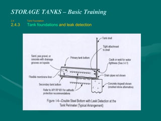
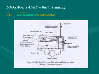
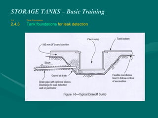
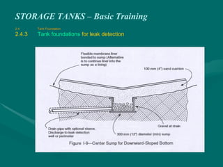
This document provides an overview and training on petroleum storage tanks. It discusses tank design types including fixed roof, floating roof, and pressurized storage tanks. It covers tank structure, fittings, inspection, measurement, and safety. The training outlines the goals of identifying tank types and equipment, understanding limitations, calculating volumes, and safe operation. Tank design considerations include product properties, stability calculations, and foundation types.