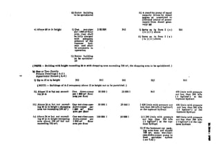
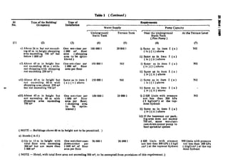
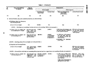
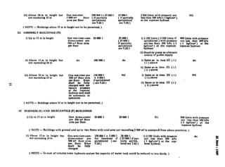
The document provides guidelines for the installation and maintenance of internal fire hydrants and hose reels on premises. It specifies requirements for components of the firefighting system like underground or terrace water tanks, fire pumps, pump houses, rise mains, downcomers, landing valves, and hose reels. Proper sizing of tanks, location of pumps, and maintenance of the system are important to effectively control fire spread and assist fire services.
The document discusses hydrant systems, which provide water for firefighting. There are two types: internal systems within buildings, and external systems outside. Internal systems include pipes, tanks, pumps and outlets. External systems are similar but provide water outside. When a hydrant valve opens, water pressure drops and the pump engages to maintain pressure. Hydrant systems must meet standards for design, installation, inspection and maintenance to effectively fight fires.
This document discusses fire pump system design according to NFPA 20 standards. It provides information on the purpose of fire pumps, acceptable pump types, sizing requirements, accessories, and operation. Fire pumps are designed to supply adequate water for sprinkler or standpipe systems by automatically starting when pressure drops and operating at 150% of rated capacity and 65% of rated head. Acceptable pump types include horizontal split case, vertical in-line, end suction, and vertical turbine configurations.
This presentation discusses NFPA 20 standards for fire pump sets. It provides background on NFPA and describes how NFPA sets standards for fire safety issues. NFPA 20 contains requirements for fire pumps, including that they must operate at 150% rated capacity at 65% total rated head. The presentation reviews pump types, motor and diesel engine selection requirements, control panels, accessories, and examples of electric and diesel pump sets.
Nfpa20 standard for the installation of stationary pumps for fire protection ...Bowen Ngo
This document summarizes the key requirements and guidelines from NFPA20 regarding fire pump installation and operation. It outlines the purpose of fire pumps to provide adequate water supply for sprinklers and standpipes. It describes common pump types like horizontal split case, vertical inline, end suction, and vertical turbine. Guidelines are provided for pump sizing within 90-150% of rated capacity. Requirements are listed for accessories like gauges, valves, relief valves and fittings. The roles of jockey pumps and pressure maintenance are explained. Operation parameters like start and stop pressures are also summarized.
Fire Hydrant System/Sprinkler System Fire Fighting Systems Fire Hydrant Syst...RajyogFireServicesPv
Fire Hydrant System,System Information,Operational Information,Fire Alarm System ......
Being one of the oldest but yet the most effective and common fire fighting solution, a well designed and a well laid out Hydrant System forms the backbone of the entire fire fighting system. It comprises of heavy duty above & underground piping with accessories. External and Fire Escape Hydrant valves are provided at every strategic location. A fire hydrant is a pipe that allows water to flow from a water main with the control of a valve in order to put out a fire.
A fire sprinkler system is an active fire protection measure, consisting of a water supply system, providing adequate pressure and flow rate to a water distribution piping system, onto which fire sprinklers are connected
An automatic sprinkler system is intended to detect, control and extinguish a fire, and warn the occupants of occurrence of fire. The installation comprises fire pumps, water storage tanks, control valve sets, sprinkler heads, flow switches, pressure switches, pipe work and valves. The system operates automatically without human intervention.
1 . Piping
2. Tank Design
3. Standpipe System
4. Pump Selection & Types
For Complete FIREFIGHTING Presentation
Check out my product on Instamojo:https://www.instamojo.com/ezazsidd1993/fire-fighting-a-complete-handbook/
This document discusses definitions and requirements related to fire pumps according to NFPA 20. It defines key terms like "authority having jurisdiction" and "approved" and discusses requirements for water supply sources, pump types, installation, and testing. Specific topics covered include acceptable suction lift for centrifugal pumps, necessary water supply flow and pressure, requirements for packaged and field-erected pump houses, and guidelines for piping, valves, and other pump components.
Comparision between NFPA and TAc rules for Power plantsvakil jagdish
The document compares rules for fire protection systems in power plants according to NFPA and TAC standards. Key differences include:
- NFPA has more detailed standards while TAC relies more on recommendatory codes
- NFPA requires hydraulic calculations, automatic systems, standby pumps, and prohibits combined water mains. TAC allows thumb rule sizing and non-automatic systems.
- NFPA has stricter requirements for pipe sizes, pressures, spacing, and protection of areas. TAC requirements are less stringent.
The document discusses fire hydrant systems used for fire protection. It describes the components of a fire hydrant system including hydrants, monitors, hoses, and pipes. It also outlines international and national standards for fire hydrant system design including spacing of hydrants, sizing of pumps and reservoirs, and classification of fire risks. The goal of a fire hydrant system is to provide a reliable water supply for extinguishing fires.
This document discusses NFPA20, which establishes standards for stationary fire pumps. It covers the purpose of fire pumps in supplying adequate water for fire protection systems. Fire pumps must be listed by authorities and sized according to NFPA standards. The document discusses various types of fire pumps and their applications. It also covers requirements for accessories like gauges, valves, and relief valves. Diesel and electric fire pump controllers are addressed, including their functions, starting methods, and alarm capabilities. Pump maintenance and testing procedures are also summarized.
Overview of Automatic Fire Sprinkler Systems.pptxM&E Engineer
An Automatic Fire Sprinkler System is a network of water-filled pipes which starts at your domestic water service line and ends with strategically spaced fire sprinkler heads located throughout your home.
1. Sprinkler system Type
WET PIPE SPRINKLER SYSTEM
DRY PIPE SPRINKLER SYSTEM
PRE-ACTION SYSTEM
DELUGE SYSTEM
WET PIPE ANTI FREEZE SYSTEM
FOAM WATER SPRINKLER SYSTEM
2. Sprinkler Selection
For COMPLETE PREMIUM BOOK PLZZ
Check out my product on Instamojo:https://www.instamojo.com/ezazsidd1993/fire-fighting-a-complete-handbook/
The document provides an overview of different types of fire fighting systems, including water-based and gas-based automatic and manual systems. It discusses components and procedures for common water-based automatic sprinkler systems like wet pipe, dry pipe, pre-action, and deluge systems. It also covers water-based manual firefighting systems and gas-based automatic and manual fire suppression systems. Diagrams and case studies are provided to illustrate key concepts and system configurations.
- Fire pumps are centrifugal pumps selected to operate between 90-140% of rated capacity and less than 150% to avoid overpressure.
- Pump rooms require 1-hour fire rated separation, emergency lighting, ventilation, and drainage.
- Suction and discharge piping must be sized properly and have the correct fittings like gauges, valves, and relief valves. Jockey pumps maintain system pressure.
- Electric and diesel fire pump controllers prioritize system operation over equipment protection to ensure reliable fire suppression.
This document provides information on fire network design, including definitions of fire terms, classes of fire, extinguishing methods and agents, passive and active fire protection systems, and considerations for firefighting system design. It discusses water capacity and rates, sources of water, fire pumps, and piping design for firewater distribution systems. The key aspects covered are fire protection philosophy, sizing systems based on the largest single fire scenario, and maintaining adequate water pressure and flow rates throughout the network.
The document provides information on fire protection systems for buildings. It discusses causes of fires and safety regulations regarding building materials and design. It also covers various active and passive fire protection components, including fire alarms, sprinklers, smoke detectors, firewalls, fire-resistant floors and walls. The types of fires are classified and different fire protection systems for residential and industrial premises are outlined, such as wet riser systems, dry riser systems, and portable fire extinguishers.
FOR DOWNLOAD THIS GO THROUGH THIS BELOW LINK
https://ezazsidd1993.stores.instamojo.com/?ref=profile_bar
INTRODUCTION OF FIRE FIGHTING
FIRE FIGHTING NETWORK COMPONENTS
Manual Fire Fighting System
Standpipe System-Landing Valve(L.V) ,Fire Hose Cabinet(F.H.C).
Fire Hydrant(F.H).
Fire Department Connection(F.D.C).
Portable Fire Extinguishers.
Pipe Types& connecting of pipes.
Pipe Accessories, Supports & Valves.
Water Source & Pumping Station.
ppt about the fire fighting foam. types of foam, there compound ,class of fire where it is used , standards which talks about fire fighting foam
for qualitative and performance requirement please refer IS 4989. and i m not able to upload the image of the reuirement
FIre Fighting Elite Fire hydraulic Calculation As per NFPA Standardsureshvsvg
This document discusses mechanical, electrical, and plumbing (MEP) systems and fire protection systems. It covers topics such as the need for MEP systems, fire triangles, causes and classifications of fires, National Fire Protection Association (NFPA) codes, firefighting systems like sprinklers and pumps, and sizing of fire water tanks and diesel tanks. The document is intended as training material for fire protection system design and hydraulic calculations using Elite software.
The document discusses fire water pump systems, including their purpose of protecting life and property. It provides an overview of key components such as the pump, driver, controller, and sensing line arrangement. The document outlines pump characteristics, rated capacities, materials used, water supply sources, and types of pumps. It also discusses pump installation, jockey pumps, diesel, electric, and steam fire pump systems and their components. Testing organizations such as UL and FM are described.
This document summarizes the fire fighting system for the PN02 medical college buildings. It describes that water is supplied from the PNU station at 120 PSI and delivered to each building through alarm check valves and zone control valves. Sprinklers are located throughout the buildings and are connected to the fire alarm system. Landing valves in staircases and fire hose cabinets are also supplied water to aid in firefighting. The system is tested and meets UL and FM approval standards.
Maintenance and inspection of lpg storage tanklpgbnhgastank
This document provides information about inspection, maintenance, cleaning, repair, and operation services for LPG storage facilities. It lists these services as well as storage tank fire protection systems and environmental protection. Contact information is provided to learn more about inspection of LPG storage tanks.
The document discusses the major components of fire attack in high-rise structures. It identifies 8 key components: 1) Incident command, 2) Water supply, 3) Gaining access/egress, 4) Operations, 5) Ventilation, 6) Evacuation. For each component, it provides details on strategies and tactics such as using elevators to access fires, connecting to standpipes, using stairwells for ventilation and evacuation, and assigning resources. The document emphasizes the importance of pre-fire planning and having strategies tailored to the unique challenges of fighting fires in high-rise buildings.
The Presentation discusses the Air-Heater Performance Indices and the Boiler Performance calculation. One can Calculate the air ingress in the air-heater and the boiler and losses incurred thereby. The presentation also describes in details about the boiler efficiency and its calculation.
The document discusses various topics related to firefighting water systems including:
1. Types of sprinkler systems such as wet, dry, pre-action, deluge, and anti-freeze systems. It also discusses standpipe systems.
2. Components of sprinkler systems such as tanks, pumps, control valves, and sprinkler heads.
3. Characteristics of sprinkler systems such as temperature ratings, K-factors, installation orientations, and sprinkler response types.
National fire codes and standards from NFPA that relate to sprinkler system design and installation are also referenced.
- Fire pumps are centrifugal pumps selected to operate between 90-140% of rated capacity and less than 150% to avoid overpressure.
- Pump rooms require 1-hour fire rated separation, emergency lighting, ventilation, and drainage.
- Suction and discharge piping must be sized properly and have the correct fittings like gauges, valves, and relief valves. Jockey pumps maintain system pressure.
- Electric and diesel fire pump controllers prioritize system operation over equipment protection to ensure reliable fire suppression.
This document provides guidelines for the installation and maintenance of fire fighting pumps according to an Indian standard. It discusses key considerations for pump houses such as adequate ventilation and accessibility. It also covers pump arrangements and layout requirements within pump houses. Guidelines are provided for the installation of fire pumps, including pump capacities, foundations, suction pipes, and priming arrangements. Maintenance of pumps is important to ensure they are in working condition during emergencies.
This document is the thesis work of Wilmer Antonio Ramirez Sarmiento titled "DESIGN AND CALCULATION OF SANITARY INSTALLATIONS OF A THREE-STORY BUILDING INTENDED FOR HOUSING APARTMENTS". It discusses the design and sizing of plumbing systems for a multi-story residential building according to Ecuadorian construction standards. The objectives are to determine the best water supply type, design internal water distribution networks and pipe diameters, design waste and storm water drainage networks, and size the water tank, elevated tank and pump power. Key elements of the plumbing system discussed include the water connection, shut-off valve, supply piping, and design parameters like flow rates, pressures and velocities
This document discusses safety in the petroleum industry. It describes how petroleum products are classified based on their flash points and defines hazardous and non-hazardous areas. It also discusses processes for identifying hazards like HAZOP and HAZAN. The majority of the document focuses on fire protection facilities and systems for petroleum installations, including requirements for fire water systems, pumps, storage, hydrants and monitors. It provides design criteria and guidelines for fire protection facilities to minimize risk in the petroleum industry.
This document provides design requirements for fire pump rooms, including considerations for workplace health and safety, ventilation, power supplies, and ensuring a safe working environment. It references relevant Australian standards and building codes. Key requirements outlined include independent access for firefighters, minimum room dimensions, clearance around pumps, drainage, ventilation, and identification of piping in accordance with standards. Designers must consider all codes and standards to address system requirements and avoid delays.
Basic training water based fire protectionSabrul Jamil
This document provides an introduction and overview of various water-based fire protection systems, including standpipe systems, wet pipe sprinkler systems, dry pipe sprinkler systems, deluge sprinkler systems, and pre-action sprinkler systems. It defines key terminology, describes common system components, and explains the purpose and function of different sprinkler head types and special application nozzles. Standards for installation and maintenance are also referenced.
Final Report (TCP/RLA/0069)
Development of Standards for the Construction and Inspection of Fishing Vessels
Final Report TCP/RLA/0069 http://www.slideshare.net/safetyforfishermen/final-report-of-project-57610513
Annex I http://www.slideshare.net/safetyforfishermen/annex-i-57610511
Annex II http://www.slideshare.net/safetyforfishermen/annex-ii-57610508
Annex III http://www.slideshare.net/safetyforfishermen/annex-iii
Annex IV http://www.slideshare.net/safetyforfishermen/annex-iv-57610500
Annex V http://www.slideshare.net/safetyforfishermen/annex-v-57610497
Annex VI http://www.slideshare.net/safetyforfishermen/annex-vi-57610495
Schedule 1 http://www.slideshare.net/safetyforfishermen/schedule-1-57610492
Schedule 2 http://www.slideshare.net/safetyforfishermen/schedule-2-57610486
Schedule 3 http://www.slideshare.net/safetyforfishermen/schedule-3-57610481
Schedule 4 http://www.slideshare.net/safetyforfishermen/schedule-4-57610477
Schedule 5 http://www.slideshare.net/safetyforfishermen/schedule-5-57610474
Schedule 6 http://www.slideshare.net/safetyforfishermen/schedule-6-57610470
Schedule 7 http://www.slideshare.net/safetyforfishermen/schedule-7-57610465
Schedule 8 http://www.slideshare.net/safetyforfishermen/schedule-8-57610456
Schedule 9 http://www.slideshare.net/safetyforfishermen/schedule-9-57610450
Schedule 10 http://www.slideshare.net/safetyforfishermen/schedule-10-57610439
Schedule 11 http://www.slideshare.net/safetyforfishermen/schedule-11-57610431
Annex VII http://www.slideshare.net/safetyforfishermen/annex-vii-57610416
Annex VIII http://www.slideshare.net/safetyforfishermen/annex-viii-57610410
Annex IX http://www.slideshare.net/safetyforfishermen/annex-ix-57610400
Annex X http://www.slideshare.net/safetyforfishermen/annex-x-57610393
Annex XI http://www.slideshare.net/safetyforfishermen/annex-xi-57610383
OISD-STD-117 Fire Protection Facilities for Petroleum Depots, Terminals, Pipe...AnupamaPanoli
The document outlines standards for fire protection facilities at petroleum depots, terminals, and pipeline installations in India. It discusses requirements for fire water systems, foam systems, control room protection, firefighting equipment, alarm systems, and organization of fire safety resources. The standards aim to minimize loss of life and property from fire through rapid containment and extinguishment. Requirements include fixed water spray and foam systems for large storage tanks, monitors and hydrants in hazardous areas, and clean agent systems for control rooms.
The State of the art in Fire Fighting 2013 V1Carsten Holbæk
The document summarizes the upgrade of the firefighting equipment on an oil terminal to meet new regulatory requirements. Key points:
- 11 tanks were equipped with permanently installed foam systems to allow storage of Class II and III flammable liquids. Other tanks near Class II tanks received irrigation systems.
- The system uses two existing diesel pumps and two new foam pumps. It provides foam coverage of tanks through permanently installed generators. Mobile equipment is also available for tank farm fires.
- Authorities approved the system in 2011. Requirements included foam capacity, contingency planning, and testing foam generators annually along with pumps and valves. All water/foam must be collected after testing.
This document provides a design basis report for a fire protection system. It includes specifications for hydrants, sprinklers, pumps, tanks, detectors, and extinguishers. It analyzes four cases of the system operating under different fire or sprinkler activation scenarios. The analysis shows the pumps can deliver sufficient flow and pressure to satisfy sprinkler and hydrant demands even under the most extreme conditions. Portable extinguishers and deluge systems are also specified for key areas to combat fires.
This document provides guidance on determining water storage capacity requirements for military facilities. It specifies that total storage capacity should be the greater of: 1) 50% of average daily domestic and industrial water needs to balance demands and provide a 1-day emergency supply, or 2) The required fireflow for the largest facility plus 50% of average domestic demand that cannot be reduced during a fire. The fireflow quantity must be maintained in storage at all times except following a fire, and the document provides other considerations for siting and types of storage facilities.
This document discusses enhancing water-based firefighting systems in tall buildings to address terrorism and arson attacks. It proposes installing additional water tanks and connections to portable pumps to ensure adequate water supply if fixed pumps fail. It also suggests integrating refuge floors into firefighting operations and considering impulse extinguishing devices as a supplemental technology, especially during critical water shortages from attacks. Firefighter response is analyzed, noting potential impacts on response time from a building's height, location, and internal conditions. Larger elevated water tanks are proposed for taller buildings to continuously supply sprinklers and hoses before portable pumps can operate, in the event of fixed pump failure.
This document provides installation, operation, and maintenance instructions for barometric condensers. It describes the two main types of condensers and their basic parts. Installation guidelines include inspecting for damage, providing sufficient clearance and supports, and properly orienting piping. Operation involves starting condensing fluid flow before other equipment, regulating flow, and properly shutting down. Troubleshooting focuses on condensing fluid, spray devices, the tailpipe, and vapor inlet. Maintenance is recommended annually and includes inspecting and cleaning strainers and spray devices. Contact information is provided for ordering spare parts.
The document discusses a new oxygen generation system installed at a PCK refinery wastewater treatment plant. The key points are:
1) The plant previously used surface aerators but now uses a new container station with three Aerzen Delta Hybrid rotary lobe compressors to inject oxygen into the bottom of an aeration basin via nozzles.
2) This new system is expected to provide more even oxygen distribution, reduce noise, odor and heat loss, and improve conditions for bacteria.
3) Initial experience with the new system will determine if one variable speed compressor or multiple compressors are needed to meet oxygen demands. The refinery plans to convert its other basins if this system proves effective.
This document provides information about wet riser systems used in high-rise buildings for firefighting. It describes the key components of a wet riser system, including landing valves, breeching inlets, wet riser pipes, pumps, and storage tanks. It explains that wet riser systems keep internal standpipes pressurized with water using jockey, duty, and standby pumps to maintain pressure. The document outlines installation and operation requirements to ensure wet riser systems effectively supply water to each floor of a building for fire brigade use.
This document provides requirements for supplying, installing, and commissioning a new XXX kVA diesel generator. Key requirements include:
- The generator must be a 2021 or newer European brand like CAT and meet ISO standards.
- The supplier must have over 25 years of generator experience in Sri Lanka and a workshop operating under ISO standards.
- The generator and all components like the engine, fuel tank, exhaust system, and silencers must be brand new and meet specifications for noise levels, temperature ranges, and corrosion resistance.
- Installation must include a sound attenuated canopy, battery and charging system, automatic engine protection, and fuel/water separator with sensor.
This document provides manufacturing specifications for double wall vertical storage tanks made of cross-linked polyethylene. It describes the materials used, tank construction details, dimensions and tolerances, accessories, and optional features. The tanks are to be rotationally molded in one piece from cross-linked polyethylene resin with UV stabilizers. Wall thickness is uniform and calculated based on pressure and safety factors. Accessories include sidewall fittings, dome fittings, manways, vents, and optional ladders, heating/insulation, and seismic restraint systems.
This document discusses the design of plumbing systems for multi-storey buildings. It notes that buildings over 2-3 stories often require pressure booster systems to supply water due to inadequate water main pressure. It describes different types of pressure booster systems including pumping to roof tanks and using hydropneumatic tanks. It also discusses drainage system considerations such as venting drain stacks and using sewage pumps or vacuum drainage systems to handle waste from lower floors.
Sealed central heating systems require components to accommodate for water expansion as the water is heated. These components include an external expansion vessel, pressure relief valve, filling loop, and pressure gauge. The expansion vessel replaces the feed and expansion cistern of vented systems. It comprises a steel cylinder divided by a rubber diaphragm that allows water to compress the air in the vessel as it expands with heat. System boilers also accommodate expansion internally without additional components. Proper sizing of the expansion vessel is necessary using formulas considering system volume, fill pressure and temperature, operating pressure and temperature, and resulting expansion factor.
This document provides a design brief for the fire-fighting systems of a proposed office building project. It outlines the scope of the fire systems, applicable codes and standards, types of systems to be installed including a fire hydrant system, automatic sprinkler system, fire detection and alarm system, portable fire extinguishers, fire signage, and an emergency assembly point. It also includes details on water storage tanks, fire pumps, wet riser systems and a public address system.
Similar to Is codes for 3844 internal fire hydrants and hose (20)
Sangyun Lee, 'Why Korea's Merger Control Occasionally Fails: A Public Choice ...Sangyun Lee
Presentation slides for a session held on June 4, 2024, at Kyoto University. This presentation is based on the presenter’s recent paper, coauthored with Hwang Lee, Professor, Korea University, with the same title, published in the Journal of Business Administration & Law, Volume 34, No. 2 (April 2024). The paper, written in Korean, is available at <https://shorturl.at/GCWcI>.
Safeguarding Against Financial Crime: AML Compliance Regulations DemystifiedPROF. PAUL ALLIEU KAMARA
To ensure the integrity of financial systems and combat illicit financial activities, understanding AML (Anti-Money Laundering) compliance regulations is crucial for financial institutions and businesses. AML compliance regulations are designed to prevent money laundering and the financing of terrorist activities by imposing specific requirements on financial institutions, including customer due diligence, monitoring, and reporting of suspicious activities (GitHub Docs).
Genocide in International Criminal Law.pptxMasoudZamani13
Excited to share insights from my recent presentation on genocide! 💡 In light of ongoing debates, it's crucial to delve into the nuances of this grave crime.
The Future of Criminal Defense Lawyer in India.pdfveteranlegal
https://veteranlegal.in/defense-lawyer-in-india/ | Criminal defense Lawyer in India has always been a vital aspect of the country's legal system. As defenders of justice, criminal Defense Lawyer play a critical role in ensuring that individuals accused of crimes receive a fair trial and that their constitutional rights are protected. As India evolves socially, economically, and technologically, the role and future of criminal Defense Lawyer are also undergoing significant changes. This comprehensive blog explores the current landscape, challenges, technological advancements, and prospects for criminal Defense Lawyer in India.
सुप्रीम कोर्ट ने यह भी माना था कि मजिस्ट्रेट का यह कर्तव्य है कि वह सुनिश्चित करे कि अधिकारी पीएमएलए के तहत निर्धारित प्रक्रिया के साथ-साथ संवैधानिक सुरक्षा उपायों का भी उचित रूप से पालन करें।
Integrating Advocacy and Legal Tactics to Tackle Online Consumer Complaintsseoglobal20
Our company bridges the gap between registered users and experienced advocates, offering a user-friendly online platform for seamless interaction. This platform empowers users to voice their grievances, particularly regarding online consumer issues. We streamline support by utilizing our team of expert advocates to provide consultancy services and initiate appropriate legal actions.
Our Online Consumer Legal Forum offers comprehensive guidance to individuals and businesses facing consumer complaints. With a dedicated team, round-the-clock support, and efficient complaint management, we are the preferred solution for addressing consumer grievances.
Our intuitive online interface allows individuals to register complaints, seek legal advice, and pursue justice conveniently. Users can submit complaints via mobile devices and send legal notices to companies directly through our portal.
Pedal to the Court Understanding Your Rights after a Cycling Collision.pdfSunsetWestLegalGroup
The immediate step is an intelligent choice; don’t procrastinate. In the aftermath of the crash, taking care of yourself and taking quick steps can help you protect yourself from significant injuries. Make sure that you have collected the essential data and information.
Pedal to the Court Understanding Your Rights after a Cycling Collision.pdf
Is codes for 3844 internal fire hydrants and hose
1. .-s
. .)
IS 8844 : 1989
Indian Standard
CODE OF PRACTICE FOR
INSTALLATION AND MAINTENANCE
OF INTERNAL FIRE HYDRANTS AND HOSE
REELS ON PREMISES
W
( First Revision)
UDC 614’843’1 : 614’843’6 : 006’76
@ BIS 1990
BUREAU OF INDIAN STANDARDS
MANAK BHAVAN, 9 BAHADUR SHAH iAFAR MARG
NEW DELHI 110002
May 1990 Price Gromp 8
( Reaffirmed 2000 )
2. Fire Fighting Sectionaf Committee, BDC 22
FOREWORD
This Indian Standard ( First Revision ) was adopted by the Bureau of Indian Standards on 20 February
1989, after the draft finalized by the Fire Fighting Sectional Committee had been approved by the Civil
Engineering Division Council.
The main intentions of provision of first-aid and in-built fire fighting arrangements are to extinguish
fire at its inception or to control its spread, to assist the fire services in dealing with the fire and in
reducing the losses suffered as a result of fire. Such arrangements are, therefore, supplementary to struc-
tural fire safety provisions laid down in relevant Indian Standards. The first-aid fire fighting arrange-
ments cover provision of portable fire extinguishers and first-aid hose reel installation with internal fire
hydrants. The selection, installation and maintenance of fire extinguishers are covered in IS 2190 : 1979
‘Code of practice for selection, installation and maintenance of portable first-aid fire extinguishers
( second revision )‘. This standard covers requirements in respect of installation and maintenance of
internal fire hydrants and hose reel systems with or without sprinkler installation for different types
of buildings. InternaI fire hydrants are intended for use by fire brigade or other trained personnel and
provide means of delivering considerable quantities of water to extinguish or to prevent the spread of
fire. Hose reels delivering smaller quantities of water can be operated even by untrained persons and
can be more rapidly brought into action in the early stages of fire. This system is more effective when
the premises is provided with an early warning device of any outbreak of fire.
This standard covering wet- and dry-riser system was first published in 1966. The revision cover
generally only wet-riser system and the provisions given are in line with the ones followed in advanced
countries. The revision also covers the details of water tanks, fire pumps and other components as well
as maintenance of system.
For the purpose of deciding whether a particular requirement of this standard is complied with, the
final value, observed or calculated, expressing the result of a test or analysis, shall be rounded off in
accordance with IS 2 : 1960 ‘Rules for rounding off numerical values ( revised )‘. The number of
significant places retained in the rounded off value should be the same as that of the specified value m
this standard.
3. IS 3844 : 1989
Indian Standard
CODE OF PRACTICE’ FOR
INSTALLATION AND MAINTENANCE
OF INTERNAL FIRE HYDRANTS AND HOSE
REELS ON PREMISES
( First Revision )
1 SCOPE
1.1 This standard
installation _and_ _
lays down the requirements of
maintenance of internal fire
hydrants and hOSe reels On the premises.
NO= -The requirements in regard to the installa-
tion and maintenance of externalfirehydrantsaro
covered in separate Indian Standard.
2 REFERENCES
2.1 The Indian Standards listed in Annex A are
necessary adjuncts to this standard.
3 TERMINOLOGY
3.0 For the purpose of this standard, the following
debitions shall apply.
3.1 Static Water Tank
Underground or surface water tank, constructed
to store water for tie fighting.purpose.
3.2 Terrace Tank
A concrete/masonry/plastic steel tank cons&ted
or erected on terrace of building for fire fighting
purpose.
3.3 PrimingTank
A small tank erected in/over the pump house
above the fire fighting pumps to keep the pump
casing and suction of the fire pump permanently
flooded.,
3.4 Foot Valve
A valve fixed in the suction strainer of the tie
pump which opens only inwards to allow in-rush
of water into the pump suction and fire pump
when the fire pump is actuated automatically/
manually.
3.5 Jockey Pump
A pump of small capacity which is set to come
into operation, automatically with drop in static
pressure in the system and to autbmatically stdp
when the pre-set pressure is reached again.
3.6 Terrace Pump
An electrically driven pump, Iocated On the
terrace connected to a terrace tank with gate Valve
on suction side and to the internal hydrant system
with non-return valve on delivery side.
3.7 Fire Pump
An electric/diesel pump installed at static water
tank to charge the wet-riser systems.
3.8 Stsnd-by Pump
A pump of same capacity as fire pump, driven by
a diesel engine or connected to any other alternate
source of electric supply.
3.9 Pump Panel
Panel comprising starting, stopping and indicating
devices of tie pumps.
3.10 Dry-Riser
An arrangement of fire fighting within the building
by means of vertical rising mains not less than
100 mm internal dia with landing valves on each
floor/landing which is normally dry but is capable
of being charged with water usually by pumping
from fire service appliances.
3.11 Down-Comer
An arrangement for fire fighting within the build-
ing by means of down-comer mains of not less
than 100 mm internal dia, connected to terrace
tank through terrace pump, gate valve and non-
return valve and landing valves on each floor/land-
ing. It is also fitted with inlet connections at ground
1
4. Is 3844 : 1989
level and air release valve at roof level for king
capable of charged with water by pumping from
fire service appliances.
3.12 Wet-Riser-cun-Down-Comer
An arrangement for fire fighting within the build-
ing by means of vertical rising mains of not less
than 100 mm internal dia with landing valves on
each floor/landing connected to terrace tank for
fire fighting purpose, through a terrace pump, gate
valve and non-return valve near the tank and to
a fire pump, gate and non-return valves, over the
static tank.
3.13 Wet-Riser
An arrangement for fire fighting within the build-
ing by means of vertical rising mains of not less
than 100 mm internal dia with landing valves
on each floor/landing for fire fighting purposes
and permanently charged with water from a
pressurized supply.
3.14 Landing Valve
An assembly comprising valve(s) and outlet(s)
connection from a riser system,
3.15 Hose Reel
Fire fighting equipment, consisting of a length of
tubing fitted with a shut-off nozzle and connected
to. a reel, wjth a permanent connection to a
pressurized water supply.
3.16 Air Release Valve
A device by which
main is expelled by
charged.
the trapped air inside a riser
water as the system is being
3.17 Air Vessel
A cylindrical_ vessel installed in the wet-riser
system at the bottom and top levels to counteract
the water hammer effects.
3.18 Pressure Switch
A switch connected on delivery line of fire pump,
or in the body of hydro-pneumatic tank at pre-set
pressure level so designed to automatically start
the fire pump or jockey pump, as the case may be,
when the pressure in the system falls below the
pre-set level.
3.19 Fire Service Inlet
A 2- or,3-way collecting head ( see 5.1.1 and
5.2.3 ) with non-return valves fitted to the down-
comer/wet-riser main, so that in case of need, fire
service can directly pressurize the system wirh
their pump.
‘ 2
3.20 Fire Service Connections
This is a 4-way collecting breeching with blank caps
( without non-return valve ) fixed to a 150-mm
dia pipe which is connected to the fire tank for
filling from external source.
4 INTERNAL HYDRANT INSTALLATION
4.0 An internal hydrant, installation comprise the
following elements:
a)
b)
4
Static or terrace tank for storing water for
fire fighting purpose;
Rise mains, down-comer mains or external
mains to feed water from the source to the
required point under pressure;
Fire fighting pump/pumps with all fitments
and components and pump control panel,
housed in a pump house; and
All necessary components like internal
hydrants ( landing valves ) and external
hydrants, hose reels, hoses and branch
pipes, suitably housed.
4.1 Undergrmnd Static Water/Terrace Tanks
4.~1 Underground Static Water Tanks
The capacity should be as given in Table 1. The
tank should not be more than 3’5 m deep having
aslope( 1 :lOO) and lm deepsumpof lx2m
at the lowest end. The side with sump should
preferably be at the front and should have an
easily removable manhole cover through which
fire engine suction hose can be lowered into the
sump for direct pimping. Static water tank
should be designed and constructed in conjunction.
with domestic tank wherever feasible.
U,nderground tanks should be provided with
compartments with external interconnection at
bottom levels having gate valves at both the ends
for periodical maintenance/cleaning purpose.
At least two manholes each of adequate size with
cover conforming to IS 1726 ( Part 1 ) : 1974,
should be provided on the tanks ( outside the
pump house ) so as to facilitate fire appliances to’
draw water from tank when necessary.
Access road to the tank where located outside the
buitding should be tit least 6 m in width and the
same should be designed suitably to bear a load
of fire appliances weighing up to 18 tonnes. The
access road should be kept free from encroachment
and obstructions at all times.
5. IS 3844: 1989
4.13 Terrace Tanks
These should be mounted on suitable girders and
plates for equal distribution of load and should
be structurally stable and the capacity shotild
be as given in Table I.
4.2 Fire Pumps and Pomp House
4.2.1 The pump house should be located prefera-
bly outside the building with a minimum clear-
ance of 6 m from adjoining buildings. The pump
house should have adequate natural ventilation
with windows, fitted with expanded metal for
protection. If the pump house, houses a diesel
pump, the exhaust pipe of the diesel engine should
be extended to outside the pump house and
exhaust discharged at an appropriate height in the
. open air. The floor of the pump house should
be sloped to the farthest end to drain away any
water leaking from glands, valves, etc. The pump
house should have normal lighting, and also
emergency lighting facility, either from a second
source or from the generator. If the pump house
is located inside the building, either on floor one
or in the basement, it should be separated from
the rest portion with a wall having 2 hour tire
rating and fire check door at its entrance having
1 hour fire rating. For pump house in basement,
forced mechanical ventilation should be provided.
Pump house in floor one should be located on
periphery of Bbuilding with access directly f%om
outside/open area.
4.2.2 Arrangement of Pumps
The pump house should be of adequate dimension
to house all the pumps with suction, delivery
pipes, fittings and starter control panel, air vessel,
etc, with adequate circulation area. A minimum
clearance of 1 m ‘at front and back and 0’75 m
on sides .and between pumps should be provided
for all .major pumps exceeding.2.280 I/min apa-
city. For smaller pumps, including jockey pumps,
the clearance required, should be 0’75 m at front
and back and 0’60 m at sides and between.pumps.
. The head room clearance for all pump .houses
should be minimum 2’75 m.
The pump control panel.which should also be
housed in the pump room should of adequate
dimension to incorporate : TPN switch and HRC
switch both of adequate capacity, selector switch
armpeter, voltmeter and phase indicating lights,
single phase preventer, start and stop push
buttons, auto-manual switch, auxiliary contactors
for inter-locking/sequence of operations and all
necessary gauges, fittings required to complete the
system ( the busbar should of copper of appro-
priate thickness 1.
Where diesel pump is provided, it should have a
. ,
separate panel, also located in the same pump
room or adjoining separate room. The panel
should have its separate battery, with battery
charging device, and auto-manual changeover
arrangement. It should incorporate an interlock-
ing device with the main pump panel so that
both the electric pump and the diesel pump do
not operate simultaneously.
Air vessel of adequate capacity should be installed
in the pump house, with pressure switches incor-
porated on the delivery line. There should be
two pressure switches - one with upper and lower
limit, for Jockey pump, and another only for
lower pressure limit for the main pump. Stopping
of main pump should be only by manual push
button which should be prominently indicated on
the pump panel.
Similar lower pressure limit switch should also
be incorporated in the diesel pump to make the
start automatically at pre-set drop in pressure.
4.2.2.1 Terrace Pump
The starting of terrace pump shouid be automatic
with pressure switch incorporated in down-comer
side so that with opening of. any hydrant valve,
or hose reel on any *floor, it will start
automatically with fall in line pressure. In addi-
tion, there should be a manual push button
starter in the starter control panel to be located
on ground floor ( floor one ) of building. Stopping
of pump should be by a push button located in
the same starter control. Both the push buttons
should be prominently indicated, and should be in
different colour for easy identification.
4.23 Suction and Delivery Pipe Sizes
The suction and delivery pipes should be of
adequate size to meet the functional requirements
of the pump, and should not be less than
following:
a)
b)
4
4
4
f)
5tlCtiOIl Delivery
450 I/min terrace pump 50 mm 5omm
900 llmin ,, ‘9, 75 mm 50 mm
1 400 l/min ,,
2 280 I/min fire p&p
IOOmm 1OOmm
150 mm 150mm
2 850 I/min ,, ,, 200mm 150 mm
4 540 llmin ,, ,, 250 mm 200mm
Where a manifold is used to make a common
suction headed, the size of manifold should be at
least equal to the cross section of the main pumps
( not counting stand-by pump ) suction inlets.
4.2.4 Priming of pumps in all cases should!
preferably be by positive suction. This can be
3
6. ls 3844 : 1989
achieved by having the pump house at Iower level
than the water tank, so as to have a permanently
flooded suction. However, where this is not
practicable, priming with the help of a priming
tank with a foot valve and strainer arrangement
may be used. The capacity of priming tank
should be 8 times the total volume of the suction
pipe, from pump up to the foot valve.
4.2.5 For wet-riser-cum-down-comer system, two
pumps of different capacity - one for the wet-
riser ( for static tank ) and the other for down-
comer system ( for terrace tank ) should be install-
ed. The pumps should be fed from normal source
of power supply and also by an alternative source
in case of failure of normal source of supply.
4.2.6 For a wet-riser system two automatic
pumps should be installed to feed the wet-rising
main, one of which should act as stand-by, each
pump should have different source of power and
so arranged that when acting as duty pump, it
will operate automatically when one or more
hydrant/hose reel is opened thus causing a drop
in pressure. The stand-by pump should be
arranged to operate automatically in case of
failure of the duty pump. There should be an
interlocking arrangement between two main
pumps so that only one should come into opera-
tion at a time.
4.2.7 An arrangement for supply of alternative
source of power automatically should be provided
to drive pumps, etc, in case of failure of normal
power supply. The alternative source should be
one of the following:
a) Supply from a diesel generating set of
adequate capacity to meet full requirement
of fire pump(s) including initial current
for direct on line/star-delta starting device
over and above the other requirements
like automatic fire detection and alarm
system, fire lift, staircase and corridor
Jighting circuits, fire pumps, pressurization
system and mechanical exhaust system. etc,
with automatic changeover. Fire pump
may be connected to diesel engine having
same power as, that of electric fire pump
with automatic changeover in case of
power supply failure with interlocking
. arrangement. ’
b) A power supply from separate. sub-station
for operating emergency services mentioned
in 4.2.7(a).
4.2.8 Pump Mounting
The pumps should be mounted firmly on concrete
foundation of minimum 75 mm thickness with
vibration absorbing layer. The foundation
should be at least equal in Iength to the common
base plate of pump, motor and flexible coupling
between pump and motor.
For diesel engines and pumps the foundation
should be equivalent to railing length of engine
and pump with flexible couplings.
All fire pumps should be. horizontal split-casting
centrifugal type with C. I. casing, bronze impellar,
and stainless steel shaft mounted on heavy
duty bearings. All metal parts coming in constant
contact with water should be suitably treated
with anti-corrosive treatment, unless these are of
non-ferrous metal.
5 RISERS
5.0 Internal hydrants form part of any of the
following systems:
a) Dry-riser system,
b) Wet-riser system,
c) Wet-riser-cum-down-comer system, and
d) Down-comer system.
5.1 Dry-RRlserSystem ( for Cold Region )
5.1.1 Dry-riser main system could be installed in. .. ...
buildings under Group A ( I, I!, 111,and iv ) ( see
IS 1641~: 1988 ) where the height of building is
above 15 m but not exceeding 24 m up to terrace
level and where the water supply for fire fighting
is immediately available either through the
underground water storage tank/tanks or through
water mains/town’s main in lieu of provision given
in Table 1. The rising main should have two-way
fire service inlet without non-return valve at
ground level, in front of each such block. It
should also be provided with an air-releasing
valve at the top level and drain valve at the bottom.
The inlet should be about 1 m from the ground
level, and easily accessible and unobstructed at
all times. Single headed landing valves conforming
to IS 5290 : 1983 should be provided at all floor
landing/staircase enclosures or other suitable
easily accessible point.
5.1.2 Dry-riser system does not include hose reel,
hose cabinets, fire hose and branch pipes.
5.2 Wet-Riser System
5.2.1 Wet-riser system should be provided in the
types of buldings as indicated in Table 1 accord-
ing to the provision mentioned. The system
should consist of a pipe or number of pipes
depending on the area and height of the buildings
permanently charged with water under pressure
with landing valves, hose reel, hose, branch pipe,
etc, at every floor level. A provision of pressure
4
7. type of buildings indicated in Table 1 according
to provisions mentioned.
differential switch to start the pump automatically,
so that water under pressure is avdrilable for
operational hydrant, hose reels, etc, as soon as the
water is drawn from hydrant landing valves
causing drop in pressure. The system also incor-
porates a stand-by pump to come into operation
automatically when the normal power supply
source fails.
5.2.2 The distribution of wet-r&x installation in
the building should be so situated as not to be
farther than ,30 m Erom any point in the area
covered by the hydrant and at -a height of 0’75 m
to 1 m from the floor. The rising mains should
not be more than SOm apart in horizontal.
5.23 Fire service inlet with gate and non-return
valve to charge the riser in the event of failure
of the static pump directly ftom the mobile pump
.of the tie services should: be provided on the
wet-riser 8ystem. The, fire service inlet for 100 mm
internal diameter rising main should have collect-
ing head with 2 numbers of 63 mm inlets and
for 150 mm rising main, collecting head with
4 numbers of 63 mm inlets should be provided.
5.3 Wet-Riser-cum-Down-CGer
5.3.1 A wet-riser-cum-down-comer system should
be provided in the type of buildings indicated in
Table 1 according to the provision mentioned.
However, instead, wet-riser system can be provided
with suitable mod%cations in their requirements
as given in 42.6.
53.2 The position and spacing of wet-riser-cwn-
!;::5c-cl;lers should be similar to wet-riser system
.
5.4 Down-ComerSystem
5.4.1 Down-comer system should be provided in
5.4.2 Single headed landing valve, connected to a
100 mm diameter pipe taken from the terrace
pump delivery should be provided at each floor/
landing, A hose reel conforming to IS 884 : 1985
and directly tapped from the down-comer pipe
should also be provided on each floor/landing.
5.5 Fire Service Inlet
5.5.1 The following facilities/arrangements should
be applicable to wet-riser systems:
a)
b)
4
A fire service inlet at ground level fitted
with a non-return valve should also be pro-
vided to the rising main of each zone for
charging it by fire service pumps, ‘in case of
failure of fire pump. If two rising mains:
are within a distance of 30 m hor$on@dlyI
a single fire service inlet will be sufhciem.
The fire service Inlet should belocated-:and,’
arranged on street side of the building,,
preferably near main entrance, prominently
marked and without any obstruction so
that fire service can connect hose lines
without difficulty.
The inlet should be located inside a box
made of 1’6 mm mild steel ‘plate with
openable 4 mm thick glass fruntage with
locking arrangements. The words ‘Fire
Service Inlet’ should be written in letters
at least 75 mm in height and 12 mm in
width in fluorescent fire red colour ( see r
IS 5 : 1978 ).
5.6 Internal diameter of rising mains/down-comer
mains for various types of building, should be as
given in Table 2.
.
5
:
8. Table 1 Typical Fire FightingIastallatimslRoqoirewnb
(Ckzuses4.1.1, 4.1.2, 5.1.1, 5.2.1, 5.3.1, 5.4.1 und 7.2)
SI Type of the Building/
No. Octupancy
Type of Requirements
Installrtloo -- - - - - -
Wa#er Supply Pump Capacity
V--cA---- p=-
Underground/ Terrace Tank Near the Underground At the Terrace Level
Static Tank Static Tank
( Fire Pump )
(1) (2) (3) (4)
I RESIDENTIAL BUILDINGS ( A )
a) Lodging or Rooming Houses
( A-l )
Dormitories ( A-3 )
i) Up to 15 m in height Nil 20 000 1 Nil Nil Nil
(6) (7)
( NOTE - No provisions are necessary for lodging and rooming houses with less than 20 persons and dormitories housing less than 20 persons; )
ii) Above 15 m in height but
not exceeding 24 m
One down-comer
per 1000 m* floor
area per floor
500001 10000 1
(200001 if
basement is
sprinklered )
Nil 450 l/mia giving a pre
iii) Above 24 m in height but
not exceeding 45 m
iv) Above 45 m in height but
not exceeding 60 m
WetAriser-cum-
down-comer per
1000 m* floor
area per floor
One wet-riser per
1 OOOm*floor area
per floor. Riser
shall be fully
chargtd with ade-
quate pressure
at the topmost
hydrant and shall
be automatic in
operation
1oooool
150000 1
loo00 1
(20000 1 in
case basement
is sprinklered
see 7.12 )
Nil
2 280 l/min giving a pres-
sure not less than 300 kPa
6zdrk$[cm* ) at topmost
i) 2 28012 820 l/min givin 8
g
ressure not less than f00
Pa (3 kgf/cm*) at the top-
most hydrant. The pump
provided will be of multi-
stage, multi-outlet ( pre-
ferably ) type with suction
and delivery sizes not less
than 15 cm dia with low
level riser upto 10 storeys
and high level riser
delivery for upper floors
ssur6 not less than
300 kPa ( 3 kgf/cm* )
at the topmost hyd-
rant
450 l/min giving a pre-
ssure not less than
300 kPa ( 3 kgf/cms )
at the topmost hyd-
rant
Nil
9. ii) Entire building
to be sprinklered
ii) A stand-by pump of equal
capacity driven by diesel
qr@?e QF vqnected to
alternate source of power
supply from diesel gene-
ra&r wt
be fully charged
with gde uatp
pressure ‘ ti8*tfie
%%d shall
hyd-
be automatic in
operation
ii) Same as in Item I (a )
( iv ) ( ii ) above
ii) Entire building
‘,” be sprmkler-
(NQTE - Building with hei@ exceedins 24 m with shopping area exceeding 750 m*, the shopping area to he sprinklered. )
b) t%e or Two Family
4
Private Dwellings ( A-2 )
Appartment Houses 5A-4 )
i) Up to lb m in bright pi* Nil Nil Nil
(NOTE - Buildings of A-2 occupancy above 15 m height not to be permitted. )
ii) Above 1s m’but not cxceed-
ing+lm
iii) Abovegm but not exceed-
in8 (ISm ip W&t ( shoeaim
afeo wt eweW4v 250p9*)
iv) Above 24 m but not exceed-
ing 45 m in height (shopping
area above 250 rns but not
exceeding 750 m*)
One down-comer 50000 1 200001 Nil
per 1880 ms 5oor
atee par floor
On@wet-riscr-cum- 50000 1 20000 1
dawn-catucr gx;
1W mr
&a Rkr floor
One +-riser-cam- 100 000 1 2OOQOl
p;;smer 5t;;
area per floor
.
Nil
450 l/min with pressure
not less than 300 kPa
( 3 kgf/cm!) at the
topmost hydrant
1 620 l/min with pressure not
less than 300 kPa (3 kgf/cm*)
450 l/min with pressure
at the‘topinost hydrant
not less than 300 kPa
. ( 3 kgf/cm’ ) at the
topmost hydrant
i) 2 280 l/min with pressure
not less than 300 kPa
980 l/min with pressure
( 3 ktfjcm’ ) at the top-
not less than 300 kPa
most ydr;tnt
( 3 kgf/cm: ) at the top-
moot hydrant
ii) If the basement car
in
ark:
8
area does not e teed!*
75 m*, same -Get-ii&%
cri&dotvntomer pump to
Feed sprinkler r system
( see 7.12 )
10. Table 1 ( Conthued )
B
,.t
Type of the Building/
Occupancy
(1) (21
v) Above 24 m but not exceed-
ing 45 m in height shopping
area exceeding 750 m* but
below 1 000 ma
vi) Above 45 m in height but
not exceeding 60 m ( with-
out shopping/with shopping
: not exceeding 250 ml )
vii) Above 45 m in height’ but
not exceeding 60m with
shopping area above 250 rn8
but not exceeding 750 m?
viii) Above 45 m in height but
not exceeding 60 m with
shopping
750 m*
area exceeding
Type of
Instnl1atioll
Reqolrcmentr
r -b f
(3)
yAwet$ser per
I floor
t
Water Supply
*
Underground/
Static Tank
Terrace Tank .
area ( shopping
area to be sprin-
klered )
One wet-riser per
1000 rn8. floor
area per floor
Same as in item
( a ) ( v ) above
I
yzeFise;i;;
area p4: floor;
( shozng sp$z
to
-klored )
(4)
1000001
15oooo 1 Nil
1500001
1500001
( NOTE - Buildings above 60 m in height not to be permitted. )
c) Hotels ( A-5 )
i) Up to ‘15 m in height with One wet-riser-cum- 50 000 1
total floor area exceeding down-comer
:mG;PUt not more than 1000 ma of fltzoef
area per floor
(5)
20 000 1
Nil
250001
200001
Pump Capacity . .
c -- A , Y
Near the Underground At tho Terrace Level
Static Tank t
( Fire Pump )
(6) (7)
i) Same as in item I (a )
(iv)( i)abovo
Nil
ii) Same as in item
( iv ) ( ii ) above
i) Same’ as in item
( iv ) ( i ) above
ii) Same an in item
(iv)(ii)abovo
i) Same as in item
( iv ) ( i ) above
ii) Same as in item
( iv ) ( ii ) above
1 (a)
1 (a)
1 (a)
I (a)
Ita)
i) 2 820 l/min with pressure
not less than 300 kPa
(3 kgf/cm’) at tho top-
most hydrant
ii) Same as in item I (a )
( iv ) ( ii ) above
iii) If the basement car park-
ing area does not exceed
750 m*, same wet-riser-
cum-down-comer pump to
food sprinkler system
Nil
Nil
Nil
1 620 l/min with pressure
not less than 300 kPa ( 3 kgf/
900 l/min with pressure
not less than 300 kPa
cm* ) at the topmost hydrant ( 3kgf/cm* ) at the top
most hydrant
( NOTE -- Hotel, with total floor area not exceeding 300 rns, to be oxemptod from provisions of this requhnent. )
11. ii) Up to 15 m; in iheight with
total floor area exceeding
1000ms
iii) Above 15 m but not,_exceed-
ing 24 m
iv) Above 24 m but not!exceed-
ing 45 m
W
v) Above 45 m
One wet-riser for
750 m* of floor
area per floor.
Wet-riser to be
t.$ charged
adequate
pressure and
automatic in
operation
One wet-riser for
750 m* floor area
per floor
do
do
1oooooi
150 0001+50000 1 200001 (if Nil
for sprinkler for
shopping
sprinklered )
i) 2 280 l/min (2 820 l/min
if sprinklered ) with pres-
area sure not less than 300 kPa
and if basement
used for car park
( 3 kgf/cm*) at the top-
most hydrant
200000 1+500001
extra require-
ment for sprink-
ler fcr shopping
area and if base-
ment used for
car park
do do
20000 1 2 280 I/min
(if sprinklered
( 2 820 I/min if Nil
provided )
sprinklered ) with pressure
not less than 300 kPa ( 3 kgf/
cm* ) at the topmost hydrant
ii) Same as in Item I ( a )
(iv) (ii) above
do i) Same as in Item I ( c )
( iii ) ( i ) above
Nil
ii) Same as in Item I (c )
( iii ) (ii ) above
i) 2 820 l/min with pressure
not less than 300 kPa
(3 kgf/cms) at the top-
most hydrant
Nil
ii) Pump of multi-stage type
or alternatively break pres-
sure wet-riser system by
interposing suction tanks
and pumps at every I5
floor level
iii) Stand-by pump of equal
capacity on alternate
source of supply
iv) All the floors to be sprin-
klered, with independent
PumP
12. Table 1 ( Continued)
Typ;fthth~ldinIgl Type of Requirements
hwtallatioll L,
Water Supply Pump Capacity
I , , A 7
Underground/
Static Tank
Terrace Tank .
( Fire Pump )
(1) (2) (3) (4) (5) (6)
II EDUCATIONAL (B) AND INSTlTUTIONAL (C) BUILDINGS
a) Buildings other than Hospitals
and Nursing Homes
i) Up to 15 m in height Nil 50000 1 Nil
( NOTE - Buildings not exceeding 3 stortys and area not exceeding 1 000 m* art exempted. )
Nil Nil
ii) Above 15 m in height but One wet-riser-cum- 50 000 1 20000 1 1620 l/qin with prt#$ure not
npt excqding 24 m height down comer per
1000 m* Boor area
less than 3OqkRa ( 3 kgf/cm* )
at the topmost hydrant
per floor/block
iii) Above 24 m in height but One wet-riser per 1BBoOo1 200001 i) 2 280 l/min with pressure
not exceeding 35 m 1OOOm*floor area ( if sprinklers not less than 300 kPa
per flOOr/blOCK art provided
in basement )
( 3 kgf/cm* )‘ r(t rbe top-
most hydrapt
ii) Sprig ler
f(reh .12)
for &Qqnpqt
( NOTE - Buildings above 35 m in height not to be permitted. )
b) Hospitals and Nursing Homes
i) Up to 15 m in height One down-comer vpq90 !
per 1 OOOm* floor
atq per ioor
200001 Nil
( NOTE - Ground floor with beds not exceeding 100 and ground and two upper floors not exceeding 50 beds are exempted. )
ii) Above 15 m in height but 20 000 1 i) 2 280 l/min (2 820 l/min
not exceeding 24 m
One wetqistr-cupt- 200 000 1+50 000 1
doq-comer if basement is if sprinklered ) with pre-
I ON! m*
for
f40qr sprinklered ssurt not less than 300 kPa
area per flqpr ( 3 kgf/cm* ) at the top-
rqst hydr;tst
At the Terrace Level
(7)
450 I/min with pressure
not less than 300 kPa
( 3 kgf/cma ) at the top-
most hydrant
900 l/min with pressure
not less than 300kPa
(3 kgf/cm*) at the top-
most hydrant
900 l/min with prts-
sure not less than 300
kPa ( 3 kgf/cmr ) at
the topmost hydrant
13. iii) Above 24 m in height but 200 000 1+50 000 I 250001 Nil
not exceeding 35 m
pnw;$riser 2 820 l/min with pressure not
floor
area per floor
( if partially
sprinklered
( if partially
sprinklered
less than 300 kPa ( 3 ltgf/cm* )
at the topmost hydrant
see 7.12 ) see 7.12 )
( NOTE - Buildings above 35 m in height not to be permitted. )
III ASSEMBLY BUILDINGS (D)
i) Up to 15 m in height
ii) Above 15 m in height but
not exceeding 24 m
iii) Above 24 m in height but
not exceeding 35 m
One wet-riser-crrm- 50 000 1
down-comer per
500 m* floor area
per floor
do 1000001 do
One wet-riser per 150 000 1
500 m* floor area + 5 000 1
if rprinklered
%?o& %; ( JCC7.12 )
charged with ad-
equate pressure
at the topmost
hvdrant and shall
Nil
200081
(250001
if partially
sprinklered
see 7.12 )
i) 2 280 l/min ( 2 820 l/min if 900 l/mln with pressure
not less than 300 kPasprinklered ) with pressure
not less than 300 kPa ( 3 ( 3 kgf/cmx ) at the
kgf cm*)
d/by rant
at the topmost topmost hydrant
ii) Stand-by pump as alternate
source of power supply
i) Same as in item III ( i )
( i ) above
do
ii) Same as in item III ( i )
( ii ) abovo
ti automatic in
operation
( NOTE - Buildings above 35 m in height not to be permitted. )
i) Same as in item III ( i )
( i ) above
Nil
ii) Same as in item III ( i )
( ii ) above
Iv BUSINESS (E) AND MERCANTILE (P) BUILDINGS
i) Up to 15 m in height One down-comer 50000 1 20000 1 Nil _
per SOUms floor
900l/min with pressure
area per floor
not less than 300kPa
(3 kgf/cm* at the
topmost hydrant
( NOTE -Buildings with ground and up to two floors with total area not exceeding 2 500 m* is exempted from above provision. )
ii) Above I5 m in height but One wet-riser-cum- 150000 1 + 5 000 1 20 000 1
not exceeding 24 m down-comer per for basement if ( 25000 1if par-
‘i) 2 280 l/mio with pressure do
500 ms floor area sprinklered (see tially sprink-
not less than 300 kPa
per floor. ;;;.r 7.12) lered see 7.12 )
( 3 kgf/cm* ) at the top-
shall be
most hydrant
charged
( NOTE- In case of reliable town hydrants system the capacity of water tank could be reduced to two thirds. )
14. Table 1 ( C’oncluded) l!A
m . .1,. . . _ -.
w
Sl
vo.
Type of the Building/
QCCoptlR~y
Type of Requirements
rIu$lati~Jl :’ ‘i- 1 E
Pump Capacity ..Water $upply
c Y
r Undergrduhdl
-I r &. . ^. I
Terrace Tauk Near the IJ!ider round
Static Tank. %
At the Terrace Level
Static Tan 8
( Fire Pump )
‘(3) ’ (4)(1) (21
iii) Above 24 m in height but
not ercceding 45 m
. .
iv) Above 45 m in height
V INDUSTRIAL BUILDINGS (G)
i) Up to 15 m in height
One weMiser per
SO0ihl floor i&a
pei floor. Riser
ihall be fully
charged with
adequate pres-
sure at the top.
most hydrant
and shall be
automatic in
operation
i) do
ii) All Ihe .flows
and basements
if any to be
$prinkIetcd
1J0000 1+soOOO I
if basement is
spr,inkleFed ( see
7.12 )
2000001+s00001
sprinklered
&e 7.12 )
One wet-riser- 50000 1
cum-down-comer
for SO0rn’ floor
area per floor
20000 1 i) 2 280 I/min with pressure 900 I/min with pressure
not less than 300 kPa not less than 300 kPa
( 3 kgf/cmX ) ‘at the top- ( 3 kgf/cm* ) at the
inost hydrant topmbst hydrant
( NOTE - Buildings with ground floor only or with ground and floors with total floor arei not exceeding 1 000 m* to be exempted. )
ii) Above 15 m iu height but Wet-riser 150000 1 i)aS;o;; as in item V ( i ) ( i ) Nil
-wt exceeding 24 m I
ii) Stand-by pump of equal
capacity on alternate
source of power supply
(S) ” m (7)
Nil i) Same as in item IV ( ii ) Nil
( i ) above
ii) Stand-by pump as alter-
nate source
EUPPlY
of powet
NilNil i) 2 820 I/min with pressure
not less than 300 kPa
_ &af$m*) at the topmost
ii) Pump of multi-stage type
alternatively break
$ssure wet-riser system
by interposing suction
tanks and pumps at every
15 floor level_
Stand-by pump of equal
capacity on altcrnato source
of sb@pIy
( NOTE - Buildings above 24 rn.not to be permitted with exception of silos and processing installations such as fractional distillation columns
and other such structures. )
15. VI STORAGE (H) AND HAZARDOUS (J) BUILDINGS
i) Single storey buildings Ring main type
hydrant system
with mains, fully
charged with
adequate pressure
at the remote
hydrant
ii) Up to 15 m in height One wet-riser-
cum-down-comer
for 500 m* floor
area per floor
1000001
( for aggregate
area not exceed-
ioglOOOm*)
150 000 litres
( for area exceed-
iog1OOOm*)
150oooI
( NOTE - Hazardous buildings above 15 m not to be permitted. )
iii) Storage buildings above 15m 000 weMiser- 15oooo 1
in height but not exceeding cum-down-comer
24m for SOOma floor
area
CI
w ( NOTE - Storage building above 24 m not to be permitted. )
Nil i) 2 280 l/min ( 2 850 l/min
if sprinklered) with pre
ssure not less than 300
kPa ( 3 kgf/cms ) at the
topmost hydrant
2oooo 1
ii) Stand-by pump of equal
capacity 00 alternate
source of power supply if _
1OOOmsarea exceeds
i) Same as in
(i ) above
item IV ( i ) 900 I/mio with pres=
sure not less than 300
ii) Same as in
( ii ) above
Nil
item IV ( i)
kPa ( 3 kgf/cm* ) at
the topmost hydrant
1) Same as in item IV ( i )
I (i)above
ii) Same as in item IV ( i )
( ii ) above
16. IS3844:lPsP
Table 2 Size of Mains
( Clause 5.6 )
Size of the Mains Type of Building
( see IS 1641: 1988 1
100 mm single outlet landing valves I) Residential buildings (A)
i) Lodging housing
ii) Dormitory
iii) Family private
dwellings
iv) Apartment houses
v) With shopping area not
exceeding 250 m*
vi) Hotel buildings up to
3 star grade
do
do
Height of Building
(3)
*Above 15 m and not exceeding 45 m
Above 15 m in height but not exceed-
ing 24 m and area not exceeding
600 m* per floor
II) Educational buildings (B) Above 15 m but not exceeding 35 m
III) Institutional buildings (C)
a) For hospitals and sanito-
rium with beds not
Above 15 m but not exceeding 25 m
exceeding 100
b) For custodial places and
mental institutions
Above 15 m but not exceeding 35 m
do IV) Assembly buildings (D) Above 15 m but not exceeding 24 m
and total floor area not exceeding
500 m*/floor
do V) Business buildings (E) Abovo I5 m but not exceeding 24m
do VI) Mercantile buildings (F) Above 15m but not exceeding 24 m
do VII) Industrial buildings ((3) Above 15 m but not exceeding 24 m
15tarmswith twin outlet landing VIII) All buildings classified Above 45 m
under(i
do IX) All buildings classified Above 24 m
under ( v’) above with shop-
ping area not exceeding 250 ms
do X) All buildings classiCed
under I ( vi ) above
Above 24 m and area exceeding 600 ms
do XI) Hotel buildings of Above 15 m
4 star and 5 star grade
do
d0
do
do
do
do
XII) All buildings classified
under II and III abovo
XIII) All buildings classified
under IV above
XIV) All buildings classified
under V above
XV) All buildings classified
under VI above
XVI) All buildings classified
under VII above
XVII) All storage buildings (H)
Above 25 m/35 m as applicable
A”msyflo~~m and area exceeding 500
Above 24 m
Above 24 m but not exceeding 35 m
Above 10 m but not exceeding 24 m
14
17. IS 3844: 1989
.5.7 The rising mains/down-comer mains should
.be of galvanized iron pipes conforming to medium
class of IS 1239 ( Part 1 ) : 1979 and their fit-
tings should be according to IS 1239 ( Part 2 ) :
1982.
5.8 The position of risers should be located within
lobby approach staircase or within, the staircase
enclosure when there is no lobby. However, the
risers or the landing valves connected to the risers
should not obstruct the means of escape, neither
reduce the width of the passage of staircase in any
way.
5.9 Landing valves should be installed on each
floor level and on the roof, if accessible, in such
a way that control line of landing valve is 1 to
1’2 m above the floor level. In the event of pump
pressure being excessive at the lower floor levels
in tall buildings a reducer should be provided in
the landing valves to Iimit operating pressure to
55 kg/cm? ( 0’5 N/mm2 ). The hoses, nozzles
and branch pipes should be kept adjacent to the
landing valves in wall boxes or in recesses.
5.10 In buildings with basements, the internal
hydrants as well as the hose reel installations
should be extended to cover the basement area
also, over and above sprinkler system, as
necessary. .
5.11A minimum of two hydrants connected to
internal hydrant system should be provided within
the courtyard of the buildings. These should
preferably be sited ‘adjacent to the roads along the
compound wall and facilities provided for fire
brigade appliances.
5.12. Fire hoses should be of sufficient length to,
carry water from the nearest source of water
supply to the. most distant point in the area
covered by a hydrant, by the normal route of
travel. For each internal hydrant ( single headed ),
there should be a total length of not less than.
30 m of 63 mm conforming to Type A of
IS 636 : 1988 or provided in two lengths of not
more than 15 m each wire wound with coupling
together with branch pipe conforming to
IS 2871 : 1983. Spare hose pipes, landing valves
lugs, valves wheel, etc. Minimum of 10 percent of
e&h item should always be kept in stock readily
available. Such spare hoses also should be in length
of not more than 15 m complete with coupling.
Hoses and accessories should be kept in hose cabi-
net painted fire red ( see IS 5 : 1978 ) and construct-
ed preferably of wood with glass front. Wall boxes
constructed of cast iron or sheet iron should be
painted at regular intervals to obviate rusting and
consequent damage to hose. A set of spare rubber
washers packed in French chalk for the purpose
of preservation should be kept readily available.
5.13 To avoid pilferage, components like landing
valves, hose couplings, branch pipes, lugs, etc,
made of aluminium alloy are recommended
depending on weather conditions.
5.14 Unless impracticable by structural considera-
tions., the landing valves should always be housed
in hose boxes. Such hose boxes shauld be made
of MS plates of 2 mm minimum thickness with
glass front. The size of the box should be adequate
to accommodate single/double headed landing
valves with 2 or 4 lengths of fire hose each of 15 m
length, and one or two branch pipes. The hose
reel may or may not be accommodated inside the
hose box. If the hose box isalso to accommodate
the hose reel, it should be of adequate dimensions.
For single headed landing valve, the front opening
glass door may be of single leaf, but for double
landing valve, double leaf doors are recommended.
The location of the riser main, along the landing
valves and hose reel, etc, should be such as to leave
enough clearance on both sides and also below
the landing valve, for smooth operations. The
landing valves should be so fitted to the riser
main, that when the fire hose is connected to it,
and charged with water under pressure, it will not
form any kin& Consideration should alsp be
given to allow adequate. spaces ,around the valve
to permit maintenance and testing.
5.14.1 For such buildings where narrow space does
not permit fixing of hose boxes, the fire hoses,
and hose reel could be fixed in suitable niches
through which the riser main has been taken up.
In such cases only a glass facing fixed on a frame
of angle iron may be used. However, these may
be used only for residential apartments,
5.15 Building fitted with wet-riser/wet-riser-a%
down-comer mains should, have access roads to’
within 6 m from the boundary line of the building
and the nearest wet-riser stack should not be
more than I5 m from the boundary line of the
building.
6 HOSE REELS
6.1 In addition to wet-riser systems, first aid hose
reels should be installed on all floors of buildings
above 15 m in height. The hose reel should be
directly taken from the wet-riser pipe by means of
a 37 mm socket and pipe to which the hose reel is
to be attached. When taken from the landing valve,
it should be connected to one of the female coupl- *
ings of the double outlet landing valves of the wet-
riser installation by means of an adapter. The hose
reel should conform to Type A of IS 884 : 1985.
6.2 The hose reel should be sited at each floor
level, staircase, lobby or mid-landing adjacent to,
exits in corridors in such a way that the nozzle of
the hose can be taken into every room and within
12
18. Is3844: 1989
6 m ofany part of a room keeping in view the
layout and obstructions. Tbe doors provided
for the hose reel recesses should he capable of
opening to approximately 180”. when installation
is in open areas, the position should be above
head height and the nozzle retainer and tbe inlet
valve should be at about 900 mm above floor
level.
6.3 It is essential that the hose reels remain
unobstructed and that they should be available
for use at all times.
6.4 In buildings that have large open floor areas
such as warehouses, the stacking arrangement
should provide for unobstructed access to the
hose reel. It may also be considered necessary to
provide guard rails around tbe hose reel position
to prevent stacking adjacent to it, care being taken
that tbe guard rails do not obstruct the operation
of the hose.
6.5 Tbe length of hose reels should be such that no
part of the floor ‘so protected is more than 6 m
away from the nozzle when the hose reel is fully
extended.
6.6 The hose reels should preferably be installed
in recesses so that they do not form obstructions
on a route of escape.
6.7 Hose reel brackets should be firmly fixed to
the wall.
7 WATER SUPPLES AND PUMPING
ARRANGEMENTS
7.1 For wet-riser mains and hose reels it is
essential that pressures and flows should at all
times be adequate to serve the designed number
of jets likely to be used. This is irrespective of
the source of water supply.
7.2 For wet-risersdown-comer system, two
pumps of different capacities ( see Table 1 ) one
for the wet-riser and the other for down-comer
system should be installed. The pumps should
be fed from normal source of power supply and
also by an alternative source in case of failure of
normal source.
7.3 For a wet-riser system, two automatic pumps
should be installed to independently feed the wet-
riser main, one of which should act as stand-by,
each pump being supplied by a different source of
power. Tbe pump shall be arranged so that when
acting as duty-pump, operate automatically when
oae or more hydrant is opened thus causing a drop
in pressure. The stand-by pump should be arranged
to operate automatically in case of failure of the
duty pump. The system should have an interlock-
ing arrangement so that only one of the pumps
operate at a time.
7.4 Priming of the main DumDand terrace bumD
in case of wet-riser-cum-dbw&omer, or boih th;:
pumps in case of wet-riser installation, should
be automatic. This can be achieved either by
having flooded suction, or by a priming tank with
foot valve arrangement. However, a flooded
suction is preferable.
7.!5Arrangements for draining a wet-riser main
should be incorporated to enable any necessary
repairs to be carried out.
7.6 To allow any trapped air in the rising main
to escape when water is pressurized into system,
air release valve should be incorporated above
tbe highest outlet of each main.
7.7 To reduce the risk of hose bursting, arrange-
ments should be made so that when tbe water is
shut off at the nozzle the static pressure in any
line of hose connected to a landing valve does
not exceed 700 kPa ( 7 kgf/cm’ ).
7.8 To reduce excess pressure at ground floor or
lower floors [ in excess of 400 kPa ( 4 kgf/cm%)
suitable arrangement ( orifice flange or other
measure ) ] should be ixicorporated in the landing
valves.
7.9 For external hydrants, piping ( water main )
should be laid preferably underground, to avoid it
getting damaged by moving vehicles, etc. To avoid
rusting, underground pipes should be either of
cast iron conforming to IS 1536: 1976or MS/G1
[ conforming to IS 1239( Part 1) : 19791,in which
case it should be properly treated with a coat of
primary paint with two coats of bitumen paint.
The pipes should be properly supported OD
pedestals - not more than 3 m apart. Under-
ground pipes should be laid 1 m below to avoid!
damage during road repair, etc, and at road
crossings where heavy vehicles are expected to
pass, it should pass through RCC pipe for addi-
tional protection.
7.10 Air Vessel
To take care of small leakages in the system, an air
vessel of appropriate size should be installed and
connected to the wet-riser main.
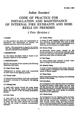
7.11 Jockey Pump
For bigger buildings or major installations, where
chance of such leakage is very considerable, it is
desirable to install a small pump ( using a small
motor and 200/300 l/min pump ) with pressure
switches for automatic start and stop.
7.12 Using Wet-Riser System Pump for Partial
Sprinkler System
In main high rise buildings, the basement is used
for car parking/housing transformers/or storages
and other floors may be used as shopping areas,
16
19. departmental stores, etc, the total area used for
such purpose being small, in such cases, the same
wet-riser pump may be used for feeding the
sprinkler system provided that:
a)
b)
4
4
the total area of the basement to be pro-
tected is less than 500 m2.
the total area utilized as shops depart-
mental stores is less than 1 000 m”.
the pump has a capacity of at least 2 850
l/min with suitable motor.
a separate stand-by pump of equal capacity
is installed, either diesel driven, or by a
generator of appropriate capacity - as
indicated in 4.2.1.
8 INITIAL TESTING
8.1 The system should be tested before use by
charging with water to a pressure of 700 kPa
( 7 kgf/cm2 ) measured at the inlet for a period
of at least 30 minutes. During this period, an
inspection of the system should be done to check
that no leakage of water is taking place at any of
the joints or landing valves and the pressure in
the system does not drop by more than 50 kPa
( 0’5 kgf/cm’ ).
8.2 After the test in accordance with 8.1 is com-
pleted, a flow test should be carried out.
9 MAINTENANCE
9.1Periodic inspections of the vicinity of all
hydrants should also be done to ensure that there
are no obstructions impeding accessibility and that
hydrant indicator plates are in position.
9.2 Periodic inspection should be done to ensure
that all isolating valves for systems are kept
locked in an ‘open’ position. Also flow and
pressure should be checked to ensure that sup-
plies have not deteriorated, leakage does not exist
and that the entire system is in satisfactory
condition.
9.3 Inlets, landing valves, drain valves, door
hinges and locking arrangements to the inlet and
landing valve boxes should be inspected every six
months. Special attention should be given to all.~
IS 3844 : 1989
that they are in satisfactory condition, so that all
equipment is ready for immediate use. Also
following checks should be done:
a) Check on the cleanliness of storage tanks,
and
b) Thorough check of the jockey pumps and
their associated mechanical and electrical
equipment.
9.4 Where any outlet on the rising mains is found
to be defective and no replacement is immediately
available, the whole valve assembly should be
removed from the main and be replaced with a
blanking off plate or plug, in order that the system
remains operative.
9.5 Hose reels should be subjected to regular
inspection to ensure that the inlet valve, the auto-
matic on/off valve, if any, glands, tubing and shut
off nozzle are sound and free from leaks, and also
to ensure that the outlet of the nozzle is not
choaked.
9.6 If jockey pumps have been installed, such
pumps and the associated mechanical and electri-
cal equipments should also be checked.
9.7 Once a year the hose reels should be com-
pletely run out and subjected to operational
water pressure to ensure that the hose is in good
condition and that the coupling joints are water-
tight. A flow test should be carried out to ensure
that discharge of at least 0’5 I/s ( 30 l/mitt ) is
achieved. If it is not possible to test every hose
reel, at least the highest reel on each rising main
should be tested.
9.8 It is essential that all defects are rectified in
the shortest possible time, to ensure that the fixed
fire-flghting equipment is restored to a satisfactory
condition in as short a time as possible.
9.9 Where, due to unforeseen dim&ties it is
necessary to leave an installation not available
for use, the fire service should be informed
immediately in order that alternative arrange-
ments may be made to cover this deficiency should
the need arise. In addition, a suitable notice to
indicate that the installation is not available for
valves, spindles, glands and washers to ensure use should be placed in a prominent position.
17
20. ANNEX A
( %lm.k.ve2.1 )
LIST’OF REFERRED INDIAN STANqARDS
IS No. Title IS No. zwe
IS 5 : 1978 Colours for ready mixed Is 1536 : 1976 Centrifugally cast ( spun )
paints and euamels ( third kon pressure pipes for
revfsion ) waters, gas and sewage
IS 636 : 1988 Non-percoiating flexible IS 1641 _ 1g88
f secmd w&ion )
fire fighting delivery hose . Code of practice for fire
( third revision ) safety of buildinga ( gene-
Is884:1%5 First-aid hose-reel for fire
ral ) : General principles
fighting (first r~k&ur )
?dgti.gradmg (;r$
IS 1239 ( Part I ) : 1979 Mild steel tubes, tubulars
revision )
and other wrought &eel IS 1726 ( Part 1) : 1974 Cast Iron manhole covers
fittings : Part 1 Wd steel and frames : Part 1
tubes (f-d revisian ) General requirements
revision 1
IS 1239(Part2): 1982 Mild steel tubes, tubulars
and other wrought steel
a 2.g71 _ 1983
.
fittings : Part 2 Mild steel
tub&us and other wrought
steel pipe fittings ( third I;s 53po ‘:1983
revision )
18
21. Standard Mark
The use of the Standard Mark is governed by the provisions of the Bureau of Indian
Standards Act, 1986 and the Rules and Regulations made thereunder. The Standard Mark on
products covered by an lndian Standard conveys the assurance that they have been produced
to comply with the requirements of that standard under a well detined system of inspection,
testing and quality control which is devised and supervised by BIS and operated by the
producer. Standard marked products are also continuously checked by BIS for conformity
to that standard as a further safeguard. Details of conditions under which a licence for the
use of the Standard Mark may be granted to manufacturers or producers may be obtained
from the Bureau of Indian Standards.
22. Bureau of xmdianstandards
BIS is a statutory institution established under the fiureau of Zndian Standards Act, 1986 to promote
harmonious development of the activities of standardization, marking and quality certification of goods
and attending to connected matters in the country.
Copyright
BIS has the copyright of all its publications. No part of these publications may be reproduced in
any form without the prior permission in writing of BIS. This does not preclude the free use, in the
course of implementing the standard, of necessary details, such as symbols and sizes, type or grade
designations. Enquiries relating to copyright be addressed to the Director ( Publications ), BIS.
Revision of IndianStandards
Indian Standards are reviewed periodically and revised, when necessary and amendments, if any, are
issued from time to time. Users of Indian Standards should ascertain that they are in possession of
the latest amendments or edition Comments on this Indian Standard may be sent to BIS giving the
following reference:
Doe : No. BDC 22 (4454)
Amendments Issaed Slice Publication
Amend No. Date of Issue Text Affected
BUREAU OF INDIAN STANDARDS
Headquarters :
Manak Bhavan, 9 Bahadur Shah Zafar Marg, New Delhi 110002
Telephones : 331 01 31, 331 13 75 Telegrams : Manaksanstha
( Common to all Offices )
Regional Offices :
Central : Manak Bhavan, 9 Bahadur Shah Zafar Marg
NEW DELHI 110002
Eastem : l/14 C. I. T. Scheme VII M, V. I. P. Road, Maniktola
CALCUTTA 700054
Telephone
331 01 31
331 13 75
37 86 62
Northern : SC0 445-446, Sector 35-C, CHANDIGARH 160036 2 1843
Southern : C. I. T. campus, IV Cross Road, MADRAS 600113 .; 41 29 16
Western : Manakalaya, E9 MIDC, Marol, Ahdheri ( East )
BOMBAY 400093
L’.
6 32 92 95
Branches : AHMADABAD. BANGALORE. BHOPAL. -BHUBANESHWARF- COIMBATORR __
FARIDABAD. GHAZIABAD. GUWAHATI. HYDERABAD. JAIPUR. KANPUR.
PATNA. TRIVANDRUM.
Printed at Printwell Printer;, Delhi, India