Downloaded 282 times

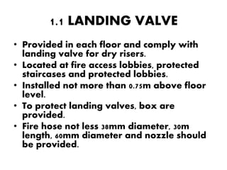


The document discusses the design standards and components for three types of firefighting water supply systems - dry riser systems, wet riser systems, and downcomer systems. For each system, it describes the requirements for landing valves on each floor, breeching inlets for fire brigade access, pipe sizing and layout, pumps and control panels, and water storage tanks. The systems are designed to provide pressurized water to fire hoses on all floors through permanently installed vertical risers.


![Final literature commercial_kus2030174979[2]](https://cdn.slidesharecdn.com/ss_thumbnails/finalliteraturecommercialkus20301749792-191123052237-thumbnail.jpg?width=640&height=640&fit=bounds)


![508602711-Fire-Protection-System-case-Study_(1)[1].pdf](https://cdn.slidesharecdn.com/ss_thumbnails/508602711-fire-protection-system-case-study11-250122132828-7e82b876-thumbnail.jpg?width=640&height=640&fit=bounds)