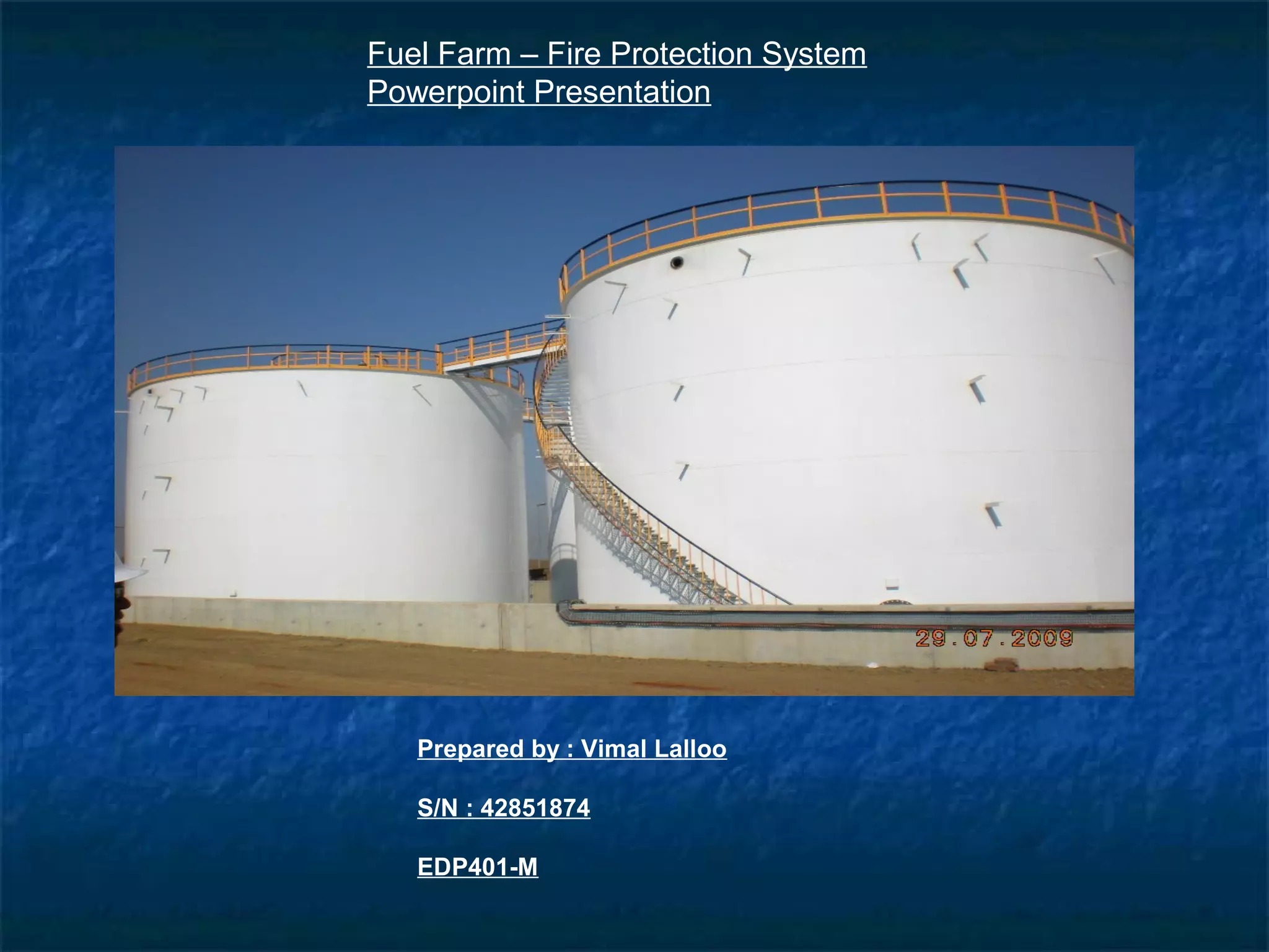
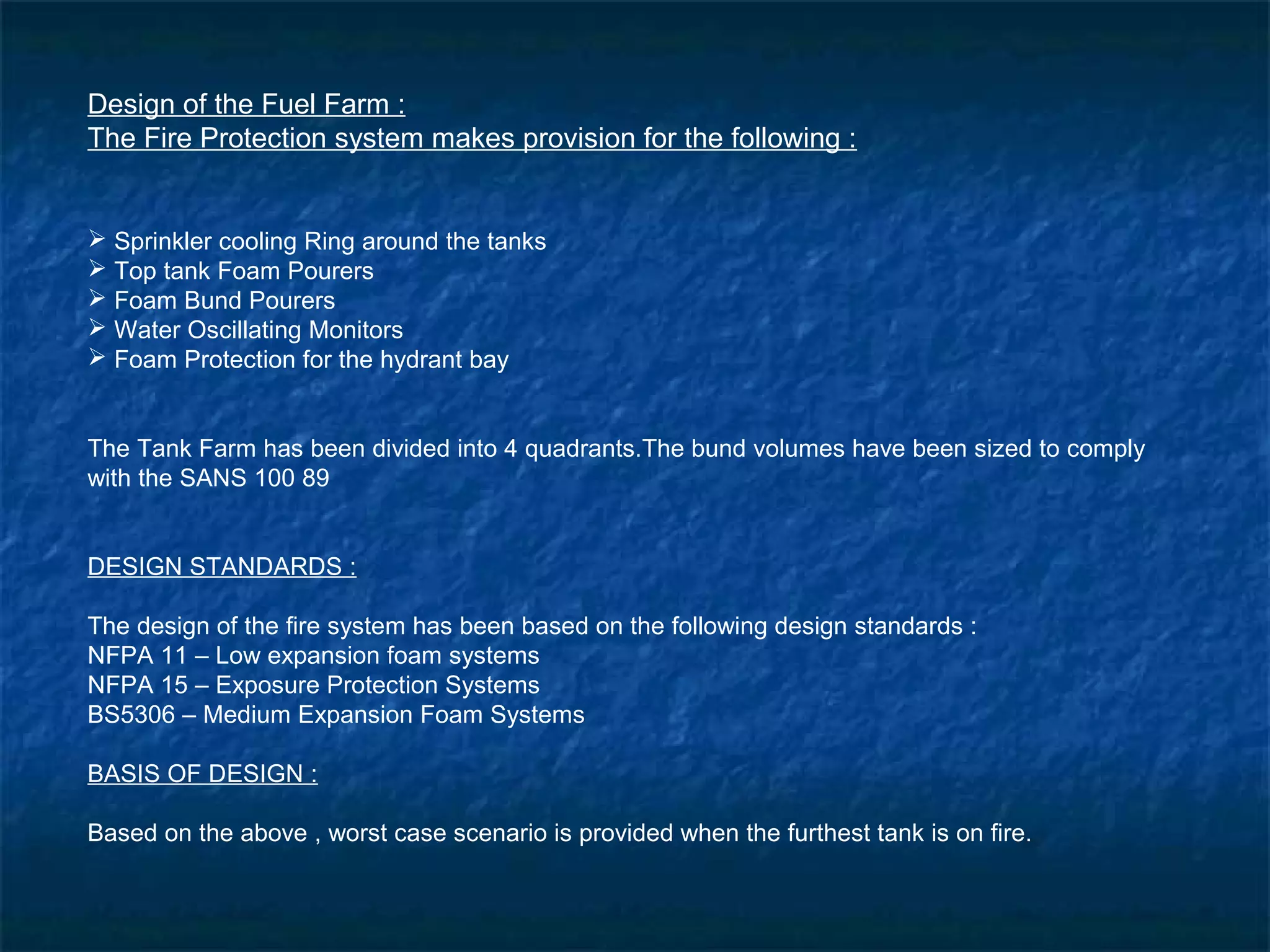
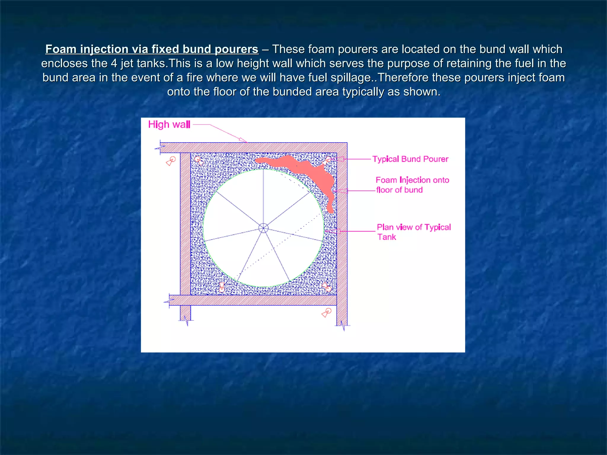
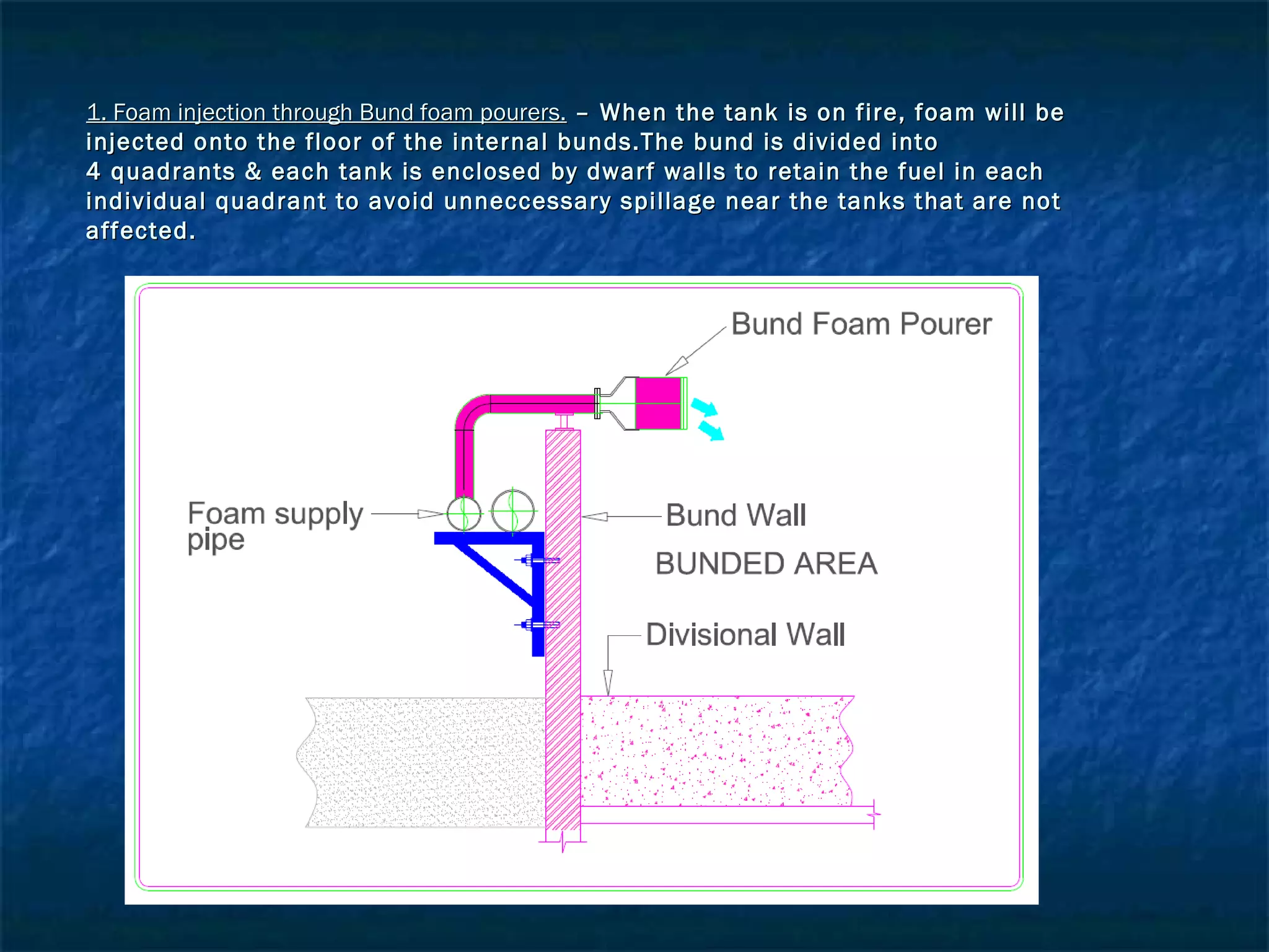
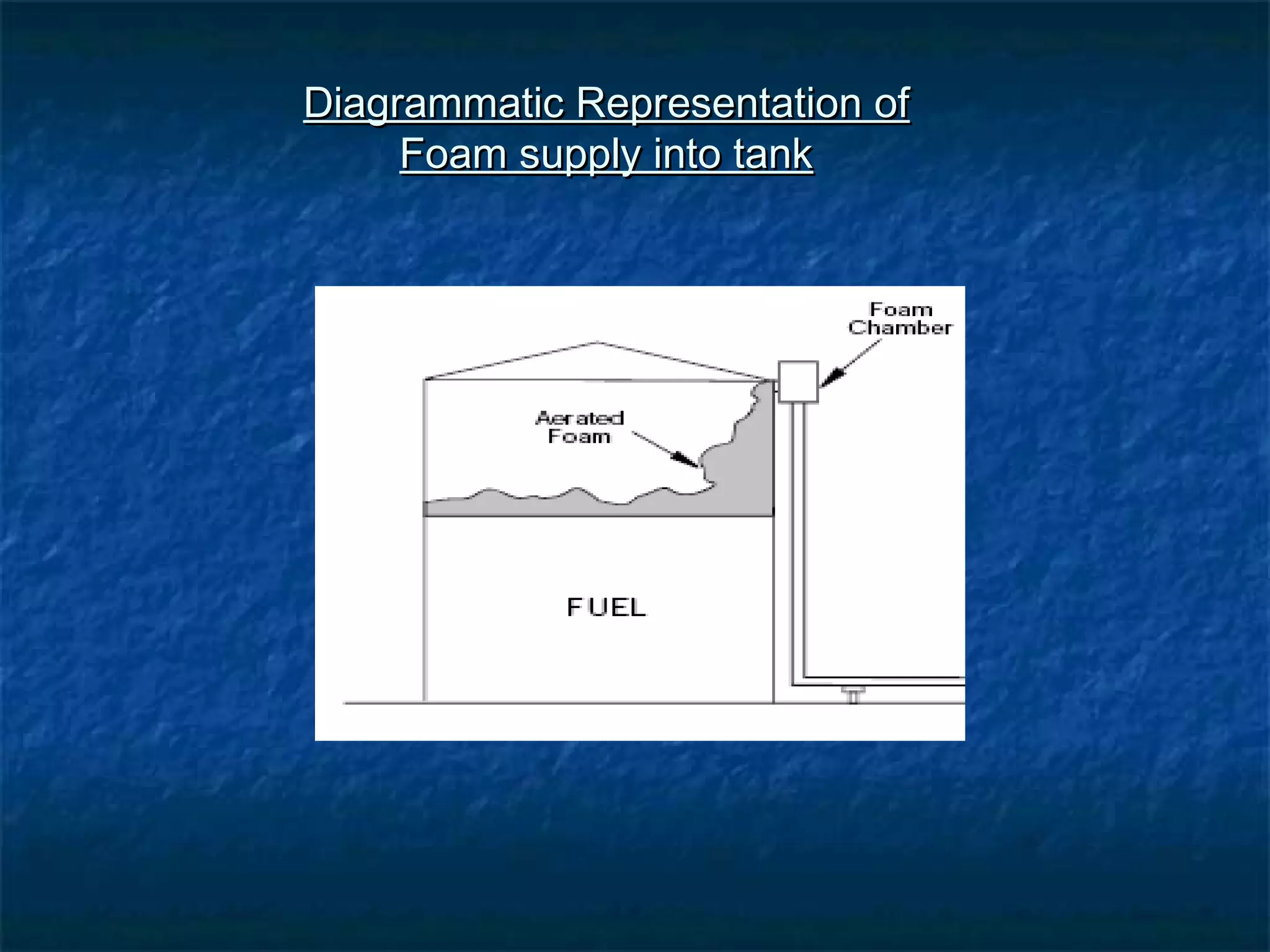
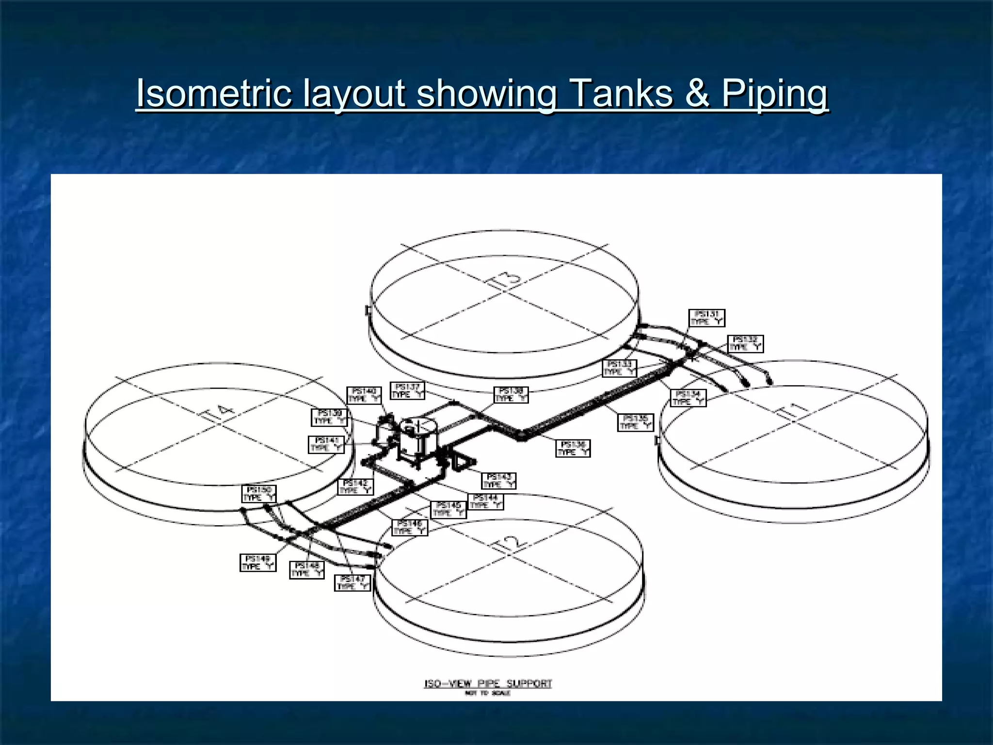
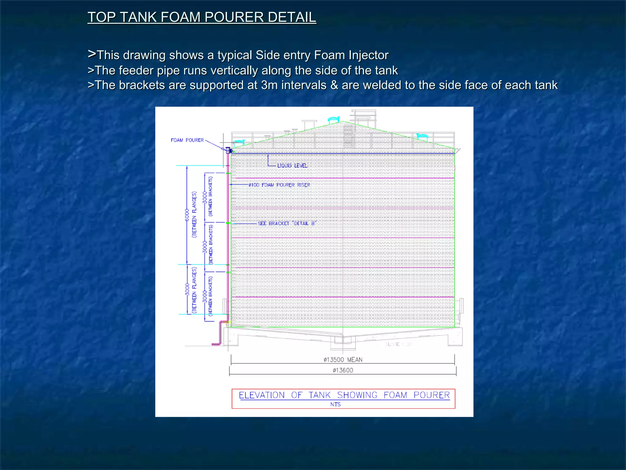
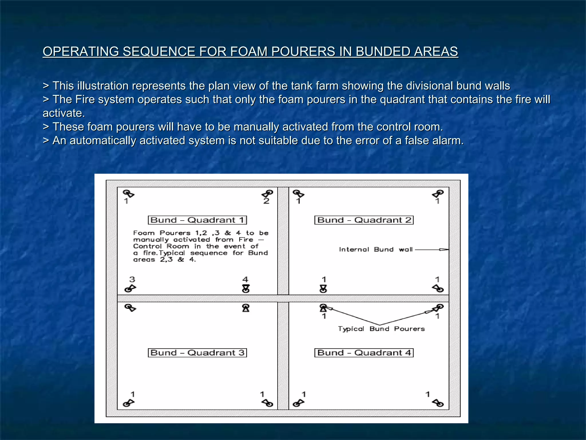
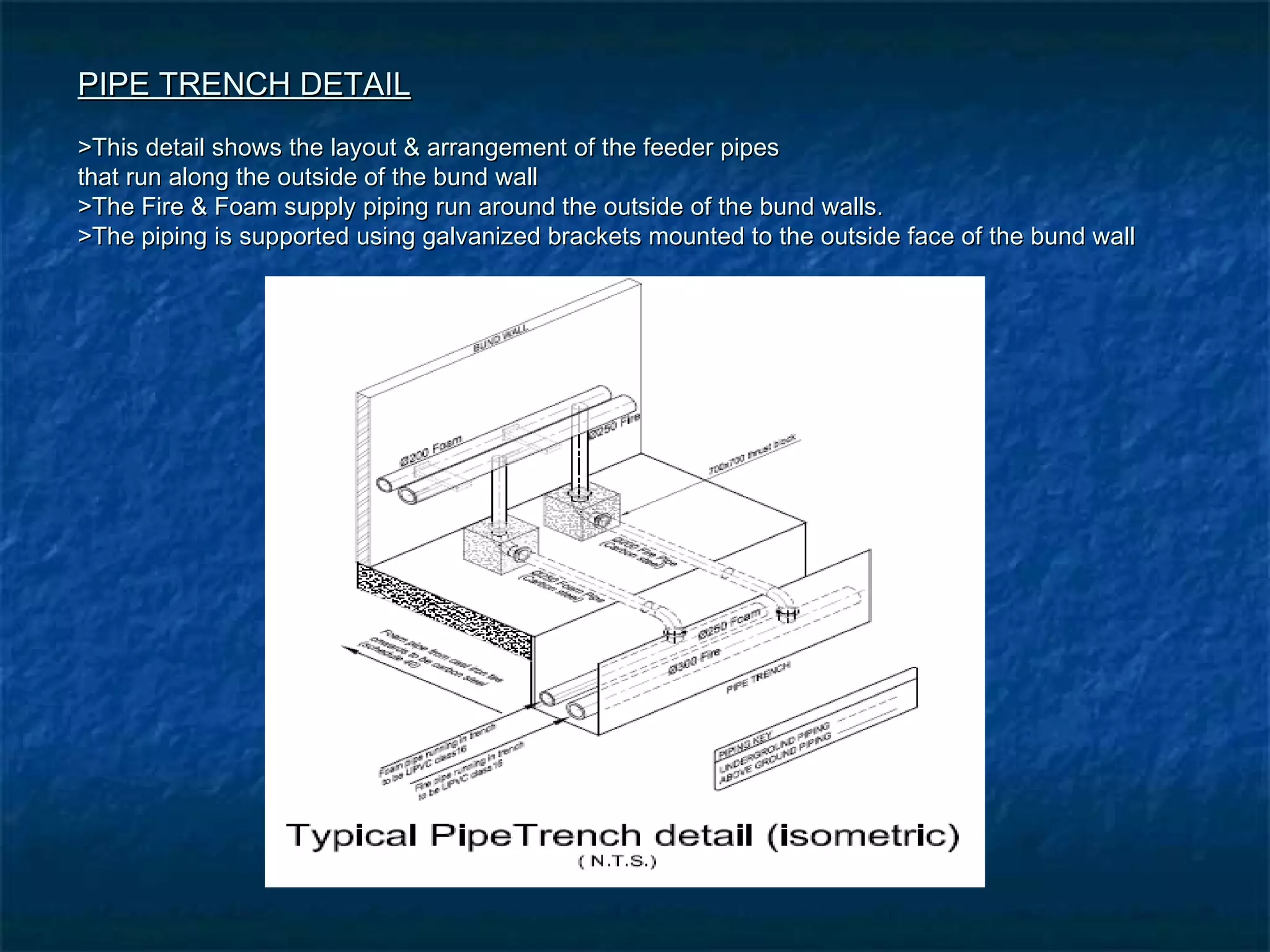
SlideShare a Scribd company logo
Fuel Farm – Fire Protection System
Powerpoint Presentation
Prepared by : Vimal Lalloo
S/N : 42851874
EDP401-M
Design of the Fuel Farm :
The Fire Protection system makes provision for the following :
 Sprinkler cooling Ring around the tanks
 Top tank Foam Pourers
 Foam Bund Pourers
 Water Oscillating Monitors
 Foam Protection for the hydrant bay
The Tank Farm has been divided into 4 quadrants.The bund volumes have been sized to comply
with the SANS 100 89
DESIGN STANDARDS :
The design of the fire system has been based on the following design standards :
NFPA 11 – Low expansion foam systems
NFPA 15 – Exposure Protection Systems
BS5306 – Medium Expansion Foam Systems
BASIS OF DESIGN :
Based on the above , worst case scenario is provided when the furthest tank is on fire.
Detail of the side entry Top Tank Foam Injector
SPRINKLER COOLING RING & SPRAY NOZZLE DETAIL
The Details below depict the sprinkler spray nozzles as well as the detail of the bracket that is welded
onto the outer tank face to support the cooling ring on which these nozzles are mounted on.
SYSTEM OPERATION IN THE EVENT OF A FIRE
 The jockey pump automatically keeps the fire water system pressurized at 1230 Kpa at all timesThe jockey pump automatically keeps the fire water system pressurized at 1230 Kpa at all times
– both water and foam mains are pressurized with water fed from the jockey pump– both water and foam mains are pressurized with water fed from the jockey pump
 All valves except the remotely controlled inbal valves in the foam and water ring mains aroundAll valves except the remotely controlled inbal valves in the foam and water ring mains around
the tank farm are normally openthe tank farm are normally open
 All application valves delivering water and foam from the ring mains into the tank farm areAll application valves delivering water and foam from the ring mains into the tank farm are
normally closednormally closed
 Water and foam pump suction and discharge valves are normally openWater and foam pump suction and discharge valves are normally open
 The following valves must be remotely opened from the fire control panel in the control room forThe following valves must be remotely opened from the fire control panel in the control room for
the bund area and the specific tank where foam is required for fire fighting:the bund area and the specific tank where foam is required for fire fighting:
 1. Foam valve for bund foam supply for fighting bund fire1. Foam valve for bund foam supply for fighting bund fire
 2. Foam valve for tank foam supply for fighting tank fire2. Foam valve for tank foam supply for fighting tank fire
 3. The water valves for tank exposure protection (cooling) must be opened remotely /manually for3. The water valves for tank exposure protection (cooling) must be opened remotely /manually for
tanks adjacent to the tank fire and all tanks in bund in case of a bund firetanks adjacent to the tank fire and all tanks in bund in case of a bund fire
 A pressure switch on the discharge manifold in the pump house will start water pumps whenA pressure switch on the discharge manifold in the pump house will start water pumps when
water main loses pressure and jockey pumps cannot sustain full pressure anymore.water main loses pressure and jockey pumps cannot sustain full pressure anymore.
 The activation of the foam bund protection or the top foam pourer control valves will relay aThe activation of the foam bund protection or the top foam pourer control valves will relay a
signal to the foam pump control panel to start the foam pumps and open the control valvesignal to the foam pump control panel to start the foam pumps and open the control valve
allowing water to flow into the foam proportioning system.allowing water to flow into the foam proportioning system.
 The Water Oscillating Monitors are used for additional tank cooling.The Water Oscillating Monitors are used for additional tank cooling.
 This procedure can be followed for any tank / bund fire scenarioThis procedure can be followed for any tank / bund fire scenario
 FIRE INSTALLATIONFIRE INSTALLATION
 Main and standby fire pump -diesel driven – KSB centrifugal pump – heat exchanger – 23000Main and standby fire pump -diesel driven – KSB centrifugal pump – heat exchanger – 23000
L/min @ 1000kpa.L/min @ 1000kpa.
 Jockey pump – 50L/min @ 1000KpaJockey pump – 50L/min @ 1000Kpa
 2 000 000L water tank2 000 000L water tank
 GMS suction and delivery pipesGMS suction and delivery pipes
 Valves, gauges and strainersValves, gauges and strainers
 Fire water test pipeFire water test pipe
 Pump Control panels with 3 leg auto startPump Control panels with 3 leg auto start
 300mm uPVC class 16 underground fire water reticulation pipes300mm uPVC class 16 underground fire water reticulation pipes
 Triple head 65 mm hydrantsTriple head 65 mm hydrants
 Tank cooling nozzles and ringTank cooling nozzles and ring
 Angus Water monitorsAngus Water monitors
 Inbal solenoid activating control valves – remotely activatedInbal solenoid activating control valves – remotely activated
 Carbon steel reticulation pipes (These pipes are designed to withstand high pressures)Carbon steel reticulation pipes (These pipes are designed to withstand high pressures)
 Isolation valves, orifice plates and gaugesIsolation valves, orifice plates and gauges
 uPVC class 16 underground reticulation pipes. (These are the supply pipes from theuPVC class 16 underground reticulation pipes. (These are the supply pipes from the
pumphouse.)pumphouse.)
 Control panel for fire system activationControl panel for fire system activation
PLAN LAYOUT OF FUEL FARMPLAN LAYOUT OF FUEL FARM
 Water oscillating monitorsWater oscillating monitors – These monitors are linked to the control panel & activate in the event of a fire.They– These monitors are linked to the control panel & activate in the event of a fire.They
are placed at suitable positions around the bund wall.In most cases, they are situated close to the bundare placed at suitable positions around the bund wall.In most cases, they are situated close to the bund
pourers.The layout & design accommodates for 8 water oscillating monitors with a maximum discharge ofpourers.The layout & design accommodates for 8 water oscillating monitors with a maximum discharge of
3600L/minute.Depending on the direction of the wind, only 2 monitors will be used at any given time.3600L/minute.Depending on the direction of the wind, only 2 monitors will be used at any given time.
Typical Plan layout of Water oscillating monitor placed internally in the bund area
1. Foam injection through top tank foam pourers.1. Foam injection through top tank foam pourers. – When the tank is on fire, foam will be– When the tank is on fire, foam will be
injected onto the surface of the fuel inside each tank.The foam supply to this foaminjected onto the surface of the fuel inside each tank.The foam supply to this foam
pourer is from a vertical feeder pipe which is run vertically from the bottom of the tankpourer is from a vertical feeder pipe which is run vertically from the bottom of the tank
to the top of the tank.This will be at side entry to the tank as shown in this illustration.to the top of the tank.This will be at side entry to the tank as shown in this illustration.
Foam injection via fixed bund pourersFoam injection via fixed bund pourers – These foam pourers are located on the bund wall which– These foam pourers are located on the bund wall which
encloses the 4 jet tanks.This is a low height wall which serves the purpose of retaining the fuel in theencloses the 4 jet tanks.This is a low height wall which serves the purpose of retaining the fuel in the
bund area in the event of a fire where we will have fuel spillage..Therefore these pourers inject foambund area in the event of a fire where we will have fuel spillage..Therefore these pourers inject foam
onto the floor of the bunded area typically as shown.onto the floor of the bunded area typically as shown.
1. Foam injection through Bund foam pourers.1. Foam injection through Bund foam pourers. – When the tank is on fire, foam will be– When the tank is on fire, foam will be
injected onto the floor of the internal bunds.The bund is divided intoinjected onto the floor of the internal bunds.The bund is divided into
4 quadrants & each tank is enclosed by dwarf walls to retain the fuel in each4 quadrants & each tank is enclosed by dwarf walls to retain the fuel in each
individual quadrant to avoid unneccessary spillage near the tanks that are notindividual quadrant to avoid unneccessary spillage near the tanks that are not
affected.affected.
Diagrammatic Representation ofDiagrammatic Representation of
Foam supply into tankFoam supply into tank
Isometric layout showing Tanks & PipingIsometric layout showing Tanks & Piping
TOP TANK FOAM POURER DETAILTOP TANK FOAM POURER DETAIL
>>This drawing shows a typical Side entry Foam InjectorThis drawing shows a typical Side entry Foam Injector
>The feeder pipe runs vertically along the side of the tank>The feeder pipe runs vertically along the side of the tank
>The brackets are supported at 3m intervals & are welded to the side face of each tank>The brackets are supported at 3m intervals & are welded to the side face of each tank
OPERATING SEQUENCE FOR FOAM POURERS IN BUNDED AREASOPERATING SEQUENCE FOR FOAM POURERS IN BUNDED AREAS
> This illustration represents the plan view of the tank farm showing the divisional bund walls> This illustration represents the plan view of the tank farm showing the divisional bund walls
> The Fire system operates such that only the foam pourers in the quadrant that contains the fire will> The Fire system operates such that only the foam pourers in the quadrant that contains the fire will
activate.activate.
> These foam pourers will have to be manually activated from the control room.> These foam pourers will have to be manually activated from the control room.
> An automatically activated system is not suitable due to the error of a false alarm.> An automatically activated system is not suitable due to the error of a false alarm.
PIPE TRENCH DETAILPIPE TRENCH DETAIL
>This detail shows the layout & arrangement of the feeder pipes>This detail shows the layout & arrangement of the feeder pipes
that run along the outside of the bund wallthat run along the outside of the bund wall
>The Fire & Foam supply piping run around the outside of the bund walls.>The Fire & Foam supply piping run around the outside of the bund walls.
>The piping is supported using galvanized brackets mounted to the outside face of the bund wall>The piping is supported using galvanized brackets mounted to the outside face of the bund wall
Objective of DesignObjective of Design
 1.1. To create a working model of a fire protection system that is specifically designedTo create a working model of a fire protection system that is specifically designed
 to accommodate for the highest possible Fire Protection coverage for a fuel farm.to accommodate for the highest possible Fire Protection coverage for a fuel farm.
 2.2. This design proposal was intended to be highly effective without compromising the feasibiltyThis design proposal was intended to be highly effective without compromising the feasibilty
 & cost factors that were involved.& cost factors that were involved.
 3.3. To provide the client with a meaningful design that could be logically & clearly understood withTo provide the client with a meaningful design that could be logically & clearly understood with
regards to cost, maintenance & reliability.regards to cost, maintenance & reliability.
 4.4. To provide a design proposal that will be accepted with regards to standards & regulations.To provide a design proposal that will be accepted with regards to standards & regulations.
 55. To keep the design as simple as possible & yet still being as effective & reliable as possible.. To keep the design as simple as possible & yet still being as effective & reliable as possible.
 ConclusionConclusion
 >The fire protection design is in accordance with international standards. The>The fire protection design is in accordance with international standards. The
equipment that has been installed for the fire protection system is UL and Lloydsequipment that has been installed for the fire protection system is UL and Lloyds
listed. All pumps are Automatic Sprinkler Inspection Bureau (ASIB) approved.listed. All pumps are Automatic Sprinkler Inspection Bureau (ASIB) approved.
 >The design of the fire protection system includes for future expansion provided that>The design of the fire protection system includes for future expansion provided that
the flow and pressure demand is not greater.the flow and pressure demand is not greater.
 >Regular maintenance and testing must be scheduled to ensure that the systems>Regular maintenance and testing must be scheduled to ensure that the systems
capabilities are not compromised. A register must be maintained for testing andcapabilities are not compromised. A register must be maintained for testing and
maintenance purposes.maintenance purposes.
 >The operator of the facility must be trained in the operation of the fire protection>The operator of the facility must be trained in the operation of the fire protection
system. The systems capabilities and limitations must be communicated to staffsystem. The systems capabilities and limitations must be communicated to staff
responsible for operating them.responsible for operating them.
 >If the type of product stored changes, the system design must be revised to>If the type of product stored changes, the system design must be revised to
accommodate the product based on the information provided on the Material Safetyaccommodate the product based on the information provided on the Material Safety
Data Sheet (MSDS).Data Sheet (MSDS).

More Related Content

What's hot

Api 653 study guide
Api 653 study guideApi 653 study guide
Api 653 study guide
JayJay Makinano
 
Tank design - word
Tank design - wordTank design - word
Tank design - word
moamen mohamed
 
Storage tank inspection presentation
Storage tank inspection presentationStorage tank inspection presentation
Storage tank inspection presentation
Ian Moore
 
Introduction to Storage Tanks
Introduction to Storage TanksIntroduction to Storage Tanks
Introduction to Storage Tanks
Ankur Sharma
 
Api 650 & 653 questions closed book with answers
Api 650 & 653 questions closed book with answersApi 650 & 653 questions closed book with answers
Api 650 & 653 questions closed book with answers
Jasminder singh
 
Summary of pressure vessel 1
Summary of pressure vessel 1Summary of pressure vessel 1
Summary of pressure vessel 1
Mohamed Basyoni
 
API 653 - Material preparado.ppt
API 653 - Material preparado.pptAPI 653 - Material preparado.ppt
API 653 - Material preparado.ppt
ClaudiaPatriciaMagaa1
 
Tank design - powerpoint slides
Tank design - powerpoint slidesTank design - powerpoint slides
Tank design - powerpoint slides
moamen mohamed
 
Inspection of Heat exchanger .pdf
Inspection of Heat exchanger .pdfInspection of Heat exchanger .pdf
Inspection of Heat exchanger .pdf
TusharNayak32
 
FIRE WATER DEMAND CALCULATION.pdf
FIRE WATER DEMAND CALCULATION.pdfFIRE WATER DEMAND CALCULATION.pdf
FIRE WATER DEMAND CALCULATION.pdf
rhamset
 
38785106 api-tank-design
38785106 api-tank-design38785106 api-tank-design
38785106 api-tank-design
141jdf
 
A comprehensive approach to tank design and tank equipment selection
A comprehensive approach to tank design and tank equipment selectionA comprehensive approach to tank design and tank equipment selection
A comprehensive approach to tank design and tank equipment selection
Mohieddin Hadidi
 
Carbon dioxide fire suppression
Carbon dioxide fire suppressionCarbon dioxide fire suppression
Carbon dioxide fire suppression
tasander
 
pipe stress analysis for piping engineering
pipe stress analysis for piping engineeringpipe stress analysis for piping engineering
pipe stress analysis for piping engineering
Yoga Sathish
 
Chris brooks storage tanks inspection, maintenance and failure
Chris brooks   storage tanks inspection, maintenance and failureChris brooks   storage tanks inspection, maintenance and failure
Chris brooks storage tanks inspection, maintenance and failure
Sreekumar K S
 
ASME Section VIII Div 1. design training
ASME Section VIII Div 1.  design trainingASME Section VIII Div 1.  design training
ASME Section VIII Div 1. design training
Sam Jose
 
Design Calculation of Venting for Atmospheric & Low Pressure Storage Tanks
Design Calculation of Venting for Atmospheric & Low Pressure Storage TanksDesign Calculation of Venting for Atmospheric & Low Pressure Storage Tanks
Design Calculation of Venting for Atmospheric & Low Pressure Storage Tanks
Kushagra Saxena
 
343312365 mt-ppt
343312365 mt-ppt343312365 mt-ppt
343312365 mt-ppt
MohamedAwad197
 

What's hot (20)

Api 653 study guide
Api 653 study guideApi 653 study guide
Api 653 study guide
 
Tank design - word
Tank design - wordTank design - word
Tank design - word
 
Storage tank inspection presentation
Storage tank inspection presentationStorage tank inspection presentation
Storage tank inspection presentation
 
Introduction to Storage Tanks
Introduction to Storage TanksIntroduction to Storage Tanks
Introduction to Storage Tanks
 
Api 650 & 653 questions closed book with answers
Api 650 & 653 questions closed book with answersApi 650 & 653 questions closed book with answers
Api 650 & 653 questions closed book with answers
 
Summary of pressure vessel 1
Summary of pressure vessel 1Summary of pressure vessel 1
Summary of pressure vessel 1
 
API 653 - Material preparado.ppt
API 653 - Material preparado.pptAPI 653 - Material preparado.ppt
API 653 - Material preparado.ppt
 
Tank design - powerpoint slides
Tank design - powerpoint slidesTank design - powerpoint slides
Tank design - powerpoint slides
 
Inspection of Heat exchanger .pdf
Inspection of Heat exchanger .pdfInspection of Heat exchanger .pdf
Inspection of Heat exchanger .pdf
 
FIRE WATER DEMAND CALCULATION.pdf
FIRE WATER DEMAND CALCULATION.pdfFIRE WATER DEMAND CALCULATION.pdf
FIRE WATER DEMAND CALCULATION.pdf
 
38785106 api-tank-design
38785106 api-tank-design38785106 api-tank-design
38785106 api-tank-design
 
A comprehensive approach to tank design and tank equipment selection
A comprehensive approach to tank design and tank equipment selectionA comprehensive approach to tank design and tank equipment selection
A comprehensive approach to tank design and tank equipment selection
 
Wellhead basics
Wellhead basicsWellhead basics
Wellhead basics
 
Carbon dioxide fire suppression
Carbon dioxide fire suppressionCarbon dioxide fire suppression
Carbon dioxide fire suppression
 
pipe stress analysis for piping engineering
pipe stress analysis for piping engineeringpipe stress analysis for piping engineering
pipe stress analysis for piping engineering
 
Chris brooks storage tanks inspection, maintenance and failure
Chris brooks   storage tanks inspection, maintenance and failureChris brooks   storage tanks inspection, maintenance and failure
Chris brooks storage tanks inspection, maintenance and failure
 
Ppt
PptPpt
Ppt
 
ASME Section VIII Div 1. design training
ASME Section VIII Div 1.  design trainingASME Section VIII Div 1.  design training
ASME Section VIII Div 1. design training
 
Design Calculation of Venting for Atmospheric & Low Pressure Storage Tanks
Design Calculation of Venting for Atmospheric & Low Pressure Storage TanksDesign Calculation of Venting for Atmospheric & Low Pressure Storage Tanks
Design Calculation of Venting for Atmospheric & Low Pressure Storage Tanks
 
343312365 mt-ppt
343312365 mt-ppt343312365 mt-ppt
343312365 mt-ppt
 

Viewers also liked

Fire Fighting
Fire FightingFire Fighting
Fire Fighting
Kerim ÇELİK
 
Fire fighting presentation
Fire  fighting presentationFire  fighting presentation
Fire fighting presentationRaghunath Patil
 
40-13041-A1-104-R08-Detail Drawing - Tank & Nozzle Orientation - AFC-TK-1255S...
40-13041-A1-104-R08-Detail Drawing - Tank & Nozzle Orientation - AFC-TK-1255S...40-13041-A1-104-R08-Detail Drawing - Tank & Nozzle Orientation - AFC-TK-1255S...
40-13041-A1-104-R08-Detail Drawing - Tank & Nozzle Orientation - AFC-TK-1255S...Shafairan Ramly
 
60-13041-A1-103-R00-Piping Plan at-TK1255S-Layout1 (2)
60-13041-A1-103-R00-Piping Plan at-TK1255S-Layout1 (2)60-13041-A1-103-R00-Piping Plan at-TK1255S-Layout1 (2)
60-13041-A1-103-R00-Piping Plan at-TK1255S-Layout1 (2)Shafairan Ramly
 
10-13041-A3-U08-R03-P&ID FOR UTILITIES LINE
10-13041-A3-U08-R03-P&ID FOR UTILITIES LINE10-13041-A3-U08-R03-P&ID FOR UTILITIES LINE
10-13041-A3-U08-R03-P&ID FOR UTILITIES LINEShafairan Ramly
 
60-13041-A1-104-R02 - Piping Plan - Stage 4 - Plan View EL. 0.590mm (2 of 10)
60-13041-A1-104-R02 - Piping Plan - Stage 4 - Plan View EL. 0.590mm  (2 of 10)60-13041-A1-104-R02 - Piping Plan - Stage 4 - Plan View EL. 0.590mm  (2 of 10)
60-13041-A1-104-R02 - Piping Plan - Stage 4 - Plan View EL. 0.590mm (2 of 10)Shafairan Ramly
 
Tank gauging-presentation-2016
Tank gauging-presentation-2016Tank gauging-presentation-2016
Tank gauging-presentation-2016
John M. Williams
 
radar tank gauging and dcs
radar tank gauging and dcsradar tank gauging and dcs
radar tank gauging and dcs
Saravana Kumar
 
Working of DCS systems
Working of DCS systemsWorking of DCS systems
Working of DCS systems
hameedakhtar155
 
Dcs operator training
Dcs operator trainingDcs operator training
Basics of Fire fighting
Basics of Fire fightingBasics of Fire fighting
Basics of Fire fighting
GAW Consultants
 
Fire Protection Systems Unit-I
Fire Protection Systems Unit-IFire Protection Systems Unit-I
Fire Protection Systems Unit-I
GAURAV. H .TANDON
 

Viewers also liked (14)

Fire Fighting
Fire FightingFire Fighting
Fire Fighting
 
Fire fighting presentation
Fire  fighting presentationFire  fighting presentation
Fire fighting presentation
 
40-13041-A1-104-R08-Detail Drawing - Tank & Nozzle Orientation - AFC-TK-1255S...
40-13041-A1-104-R08-Detail Drawing - Tank & Nozzle Orientation - AFC-TK-1255S...40-13041-A1-104-R08-Detail Drawing - Tank & Nozzle Orientation - AFC-TK-1255S...
40-13041-A1-104-R08-Detail Drawing - Tank & Nozzle Orientation - AFC-TK-1255S...
 
60-13041-A1-103-R00-Piping Plan at-TK1255S-Layout1 (2)
60-13041-A1-103-R00-Piping Plan at-TK1255S-Layout1 (2)60-13041-A1-103-R00-Piping Plan at-TK1255S-Layout1 (2)
60-13041-A1-103-R00-Piping Plan at-TK1255S-Layout1 (2)
 
10-13041-A3-U08-R03-P&ID FOR UTILITIES LINE
10-13041-A3-U08-R03-P&ID FOR UTILITIES LINE10-13041-A3-U08-R03-P&ID FOR UTILITIES LINE
10-13041-A3-U08-R03-P&ID FOR UTILITIES LINE
 
60-13041-A1-104-R02 - Piping Plan - Stage 4 - Plan View EL. 0.590mm (2 of 10)
60-13041-A1-104-R02 - Piping Plan - Stage 4 - Plan View EL. 0.590mm  (2 of 10)60-13041-A1-104-R02 - Piping Plan - Stage 4 - Plan View EL. 0.590mm  (2 of 10)
60-13041-A1-104-R02 - Piping Plan - Stage 4 - Plan View EL. 0.590mm (2 of 10)
 
Tank gauging-presentation-2016
Tank gauging-presentation-2016Tank gauging-presentation-2016
Tank gauging-presentation-2016
 
radar tank gauging and dcs
radar tank gauging and dcsradar tank gauging and dcs
radar tank gauging and dcs
 
Fire pumps
Fire pumpsFire pumps
Fire pumps
 
Working of DCS systems
Working of DCS systemsWorking of DCS systems
Working of DCS systems
 
Dcs operator training
Dcs operator trainingDcs operator training
Dcs operator training
 
DCS Or PLC
DCS Or PLCDCS Or PLC
DCS Or PLC
 
Basics of Fire fighting
Basics of Fire fightingBasics of Fire fighting
Basics of Fire fighting
 
Fire Protection Systems Unit-I
Fire Protection Systems Unit-IFire Protection Systems Unit-I
Fire Protection Systems Unit-I
 

Similar to EDP401-M - Presentation - 07.02.2010

AMMONIA storage
AMMONIA storageAMMONIA storage
AMMONIA storage
Rohit choudhary
 
Steam boiler
Steam boilerSteam boiler
Steam boiler
Milan vaghani
 
Boiler safety
Boiler safetyBoiler safety
Boiler safety
Santosh Kumar
 
Cochran Boiler
Cochran Boiler Cochran Boiler
Cochran Boiler
Asaye Dessie
 
Boiler mountings
Boiler mountingsBoiler mountings
Boiler mountings
jitendra kumar
 
Steam boiler
Steam boilerSteam boiler
Steam boiler
Haseeb Butt
 
FIRE FIGHTING NOTES PART 02 BY ER. EZAZUL HAQUE SIDDIQUE .PPT
FIRE FIGHTING NOTES PART 02 BY ER. EZAZUL HAQUE SIDDIQUE .PPTFIRE FIGHTING NOTES PART 02 BY ER. EZAZUL HAQUE SIDDIQUE .PPT
FIRE FIGHTING NOTES PART 02 BY ER. EZAZUL HAQUE SIDDIQUE .PPT
MEP ENGINEER'S SERVICES
 
SandBlasting Products
SandBlasting ProductsSandBlasting Products
SandBlasting ProductsNestor Aponte
 
FF DESIGN BASIS REPORT.pdf
FF DESIGN BASIS REPORT.pdfFF DESIGN BASIS REPORT.pdf
FF DESIGN BASIS REPORT.pdf
ssuser0aa2d5
 
Thermal Power Plant - Emergency situations
Thermal Power Plant   -   Emergency situations Thermal Power Plant   -   Emergency situations
Thermal Power Plant - Emergency situations
Ashish Kumar Jain
 
Deep well pumps in USA
Deep well pumps in USADeep well pumps in USA
Deep well pumps in USA
Jennifer Morrison
 
Basic training water based fire protection
Basic training  water based fire protectionBasic training  water based fire protection
Basic training water based fire protection
Sabrul Jamil
 
Floating Roof Operation.pptx
Floating Roof Operation.pptxFloating Roof Operation.pptx
Floating Roof Operation.pptx
RobinRohit2
 
BS2 Fire protection 1
BS2 Fire protection 1BS2 Fire protection 1
BS2 Fire protection 1
Est
 
Fs sprinkler systems
Fs sprinkler systemsFs sprinkler systems
Fs sprinkler systems
Aamir Farhan Sheikh
 
Keraflo Aylesbury KB Type Float Valve - Spec Sheet
Keraflo Aylesbury KB Type Float Valve - Spec SheetKeraflo Aylesbury KB Type Float Valve - Spec Sheet
Keraflo Aylesbury KB Type Float Valve - Spec Sheet
Thorne & Derrick UK
 
Sabardairy Training Report
Sabardairy Training ReportSabardairy Training Report
Sabardairy Training Report
NiravDesai66
 
Comfortable KODigital cwmf portables plant
Comfortable KODigital cwmf portables plantComfortable KODigital cwmf portables plant
Comfortable KODigital cwmf portables plant
kobelco2567
 

Similar to EDP401-M - Presentation - 07.02.2010 (20)

Sprinkler system
Sprinkler systemSprinkler system
Sprinkler system
 
AMMONIA storage
AMMONIA storageAMMONIA storage
AMMONIA storage
 
Steam boiler
Steam boilerSteam boiler
Steam boiler
 
Boiler safety
Boiler safetyBoiler safety
Boiler safety
 
Cochran Boiler
Cochran Boiler Cochran Boiler
Cochran Boiler
 
Boiler mountings
Boiler mountingsBoiler mountings
Boiler mountings
 
Steam boiler
Steam boilerSteam boiler
Steam boiler
 
Boiler Mountings
Boiler MountingsBoiler Mountings
Boiler Mountings
 
FIRE FIGHTING NOTES PART 02 BY ER. EZAZUL HAQUE SIDDIQUE .PPT
FIRE FIGHTING NOTES PART 02 BY ER. EZAZUL HAQUE SIDDIQUE .PPTFIRE FIGHTING NOTES PART 02 BY ER. EZAZUL HAQUE SIDDIQUE .PPT
FIRE FIGHTING NOTES PART 02 BY ER. EZAZUL HAQUE SIDDIQUE .PPT
 
SandBlasting Products
SandBlasting ProductsSandBlasting Products
SandBlasting Products
 
FF DESIGN BASIS REPORT.pdf
FF DESIGN BASIS REPORT.pdfFF DESIGN BASIS REPORT.pdf
FF DESIGN BASIS REPORT.pdf
 
Thermal Power Plant - Emergency situations
Thermal Power Plant   -   Emergency situations Thermal Power Plant   -   Emergency situations
Thermal Power Plant - Emergency situations
 
Deep well pumps in USA
Deep well pumps in USADeep well pumps in USA
Deep well pumps in USA
 
Basic training water based fire protection
Basic training  water based fire protectionBasic training  water based fire protection
Basic training water based fire protection
 
Floating Roof Operation.pptx
Floating Roof Operation.pptxFloating Roof Operation.pptx
Floating Roof Operation.pptx
 
BS2 Fire protection 1
BS2 Fire protection 1BS2 Fire protection 1
BS2 Fire protection 1
 
Fs sprinkler systems
Fs sprinkler systemsFs sprinkler systems
Fs sprinkler systems
 
Keraflo Aylesbury KB Type Float Valve - Spec Sheet
Keraflo Aylesbury KB Type Float Valve - Spec SheetKeraflo Aylesbury KB Type Float Valve - Spec Sheet
Keraflo Aylesbury KB Type Float Valve - Spec Sheet
 
Sabardairy Training Report
Sabardairy Training ReportSabardairy Training Report
Sabardairy Training Report
 
Comfortable KODigital cwmf portables plant
Comfortable KODigital cwmf portables plantComfortable KODigital cwmf portables plant
Comfortable KODigital cwmf portables plant
 

EDP401-M - Presentation - 07.02.2010

  • 1. Fuel Farm – Fire Protection System Powerpoint Presentation Prepared by : Vimal Lalloo S/N : 42851874 EDP401-M
  • 2. Design of the Fuel Farm : The Fire Protection system makes provision for the following :  Sprinkler cooling Ring around the tanks  Top tank Foam Pourers  Foam Bund Pourers  Water Oscillating Monitors  Foam Protection for the hydrant bay The Tank Farm has been divided into 4 quadrants.The bund volumes have been sized to comply with the SANS 100 89 DESIGN STANDARDS : The design of the fire system has been based on the following design standards : NFPA 11 – Low expansion foam systems NFPA 15 – Exposure Protection Systems BS5306 – Medium Expansion Foam Systems BASIS OF DESIGN : Based on the above , worst case scenario is provided when the furthest tank is on fire.
  • 3. Detail of the side entry Top Tank Foam Injector
  • 4. SPRINKLER COOLING RING & SPRAY NOZZLE DETAIL The Details below depict the sprinkler spray nozzles as well as the detail of the bracket that is welded onto the outer tank face to support the cooling ring on which these nozzles are mounted on.
  • 5. SYSTEM OPERATION IN THE EVENT OF A FIRE  The jockey pump automatically keeps the fire water system pressurized at 1230 Kpa at all timesThe jockey pump automatically keeps the fire water system pressurized at 1230 Kpa at all times – both water and foam mains are pressurized with water fed from the jockey pump– both water and foam mains are pressurized with water fed from the jockey pump  All valves except the remotely controlled inbal valves in the foam and water ring mains aroundAll valves except the remotely controlled inbal valves in the foam and water ring mains around the tank farm are normally openthe tank farm are normally open  All application valves delivering water and foam from the ring mains into the tank farm areAll application valves delivering water and foam from the ring mains into the tank farm are normally closednormally closed  Water and foam pump suction and discharge valves are normally openWater and foam pump suction and discharge valves are normally open  The following valves must be remotely opened from the fire control panel in the control room forThe following valves must be remotely opened from the fire control panel in the control room for the bund area and the specific tank where foam is required for fire fighting:the bund area and the specific tank where foam is required for fire fighting:  1. Foam valve for bund foam supply for fighting bund fire1. Foam valve for bund foam supply for fighting bund fire  2. Foam valve for tank foam supply for fighting tank fire2. Foam valve for tank foam supply for fighting tank fire  3. The water valves for tank exposure protection (cooling) must be opened remotely /manually for3. The water valves for tank exposure protection (cooling) must be opened remotely /manually for tanks adjacent to the tank fire and all tanks in bund in case of a bund firetanks adjacent to the tank fire and all tanks in bund in case of a bund fire  A pressure switch on the discharge manifold in the pump house will start water pumps whenA pressure switch on the discharge manifold in the pump house will start water pumps when water main loses pressure and jockey pumps cannot sustain full pressure anymore.water main loses pressure and jockey pumps cannot sustain full pressure anymore.  The activation of the foam bund protection or the top foam pourer control valves will relay aThe activation of the foam bund protection or the top foam pourer control valves will relay a signal to the foam pump control panel to start the foam pumps and open the control valvesignal to the foam pump control panel to start the foam pumps and open the control valve allowing water to flow into the foam proportioning system.allowing water to flow into the foam proportioning system.  The Water Oscillating Monitors are used for additional tank cooling.The Water Oscillating Monitors are used for additional tank cooling.  This procedure can be followed for any tank / bund fire scenarioThis procedure can be followed for any tank / bund fire scenario
  • 6.  FIRE INSTALLATIONFIRE INSTALLATION  Main and standby fire pump -diesel driven – KSB centrifugal pump – heat exchanger – 23000Main and standby fire pump -diesel driven – KSB centrifugal pump – heat exchanger – 23000 L/min @ 1000kpa.L/min @ 1000kpa.  Jockey pump – 50L/min @ 1000KpaJockey pump – 50L/min @ 1000Kpa  2 000 000L water tank2 000 000L water tank  GMS suction and delivery pipesGMS suction and delivery pipes  Valves, gauges and strainersValves, gauges and strainers  Fire water test pipeFire water test pipe  Pump Control panels with 3 leg auto startPump Control panels with 3 leg auto start  300mm uPVC class 16 underground fire water reticulation pipes300mm uPVC class 16 underground fire water reticulation pipes  Triple head 65 mm hydrantsTriple head 65 mm hydrants  Tank cooling nozzles and ringTank cooling nozzles and ring  Angus Water monitorsAngus Water monitors  Inbal solenoid activating control valves – remotely activatedInbal solenoid activating control valves – remotely activated  Carbon steel reticulation pipes (These pipes are designed to withstand high pressures)Carbon steel reticulation pipes (These pipes are designed to withstand high pressures)  Isolation valves, orifice plates and gaugesIsolation valves, orifice plates and gauges  uPVC class 16 underground reticulation pipes. (These are the supply pipes from theuPVC class 16 underground reticulation pipes. (These are the supply pipes from the pumphouse.)pumphouse.)  Control panel for fire system activationControl panel for fire system activation
  • 7. PLAN LAYOUT OF FUEL FARMPLAN LAYOUT OF FUEL FARM
  • 8.  Water oscillating monitorsWater oscillating monitors – These monitors are linked to the control panel & activate in the event of a fire.They– These monitors are linked to the control panel & activate in the event of a fire.They are placed at suitable positions around the bund wall.In most cases, they are situated close to the bundare placed at suitable positions around the bund wall.In most cases, they are situated close to the bund pourers.The layout & design accommodates for 8 water oscillating monitors with a maximum discharge ofpourers.The layout & design accommodates for 8 water oscillating monitors with a maximum discharge of 3600L/minute.Depending on the direction of the wind, only 2 monitors will be used at any given time.3600L/minute.Depending on the direction of the wind, only 2 monitors will be used at any given time. Typical Plan layout of Water oscillating monitor placed internally in the bund area
  • 9. 1. Foam injection through top tank foam pourers.1. Foam injection through top tank foam pourers. – When the tank is on fire, foam will be– When the tank is on fire, foam will be injected onto the surface of the fuel inside each tank.The foam supply to this foaminjected onto the surface of the fuel inside each tank.The foam supply to this foam pourer is from a vertical feeder pipe which is run vertically from the bottom of the tankpourer is from a vertical feeder pipe which is run vertically from the bottom of the tank to the top of the tank.This will be at side entry to the tank as shown in this illustration.to the top of the tank.This will be at side entry to the tank as shown in this illustration.
  • 10. Foam injection via fixed bund pourersFoam injection via fixed bund pourers – These foam pourers are located on the bund wall which– These foam pourers are located on the bund wall which encloses the 4 jet tanks.This is a low height wall which serves the purpose of retaining the fuel in theencloses the 4 jet tanks.This is a low height wall which serves the purpose of retaining the fuel in the bund area in the event of a fire where we will have fuel spillage..Therefore these pourers inject foambund area in the event of a fire where we will have fuel spillage..Therefore these pourers inject foam onto the floor of the bunded area typically as shown.onto the floor of the bunded area typically as shown.
  • 11. 1. Foam injection through Bund foam pourers.1. Foam injection through Bund foam pourers. – When the tank is on fire, foam will be– When the tank is on fire, foam will be injected onto the floor of the internal bunds.The bund is divided intoinjected onto the floor of the internal bunds.The bund is divided into 4 quadrants & each tank is enclosed by dwarf walls to retain the fuel in each4 quadrants & each tank is enclosed by dwarf walls to retain the fuel in each individual quadrant to avoid unneccessary spillage near the tanks that are notindividual quadrant to avoid unneccessary spillage near the tanks that are not affected.affected.
  • 12. Diagrammatic Representation ofDiagrammatic Representation of Foam supply into tankFoam supply into tank
  • 13. Isometric layout showing Tanks & PipingIsometric layout showing Tanks & Piping
  • 14. TOP TANK FOAM POURER DETAILTOP TANK FOAM POURER DETAIL >>This drawing shows a typical Side entry Foam InjectorThis drawing shows a typical Side entry Foam Injector >The feeder pipe runs vertically along the side of the tank>The feeder pipe runs vertically along the side of the tank >The brackets are supported at 3m intervals & are welded to the side face of each tank>The brackets are supported at 3m intervals & are welded to the side face of each tank
  • 15. OPERATING SEQUENCE FOR FOAM POURERS IN BUNDED AREASOPERATING SEQUENCE FOR FOAM POURERS IN BUNDED AREAS > This illustration represents the plan view of the tank farm showing the divisional bund walls> This illustration represents the plan view of the tank farm showing the divisional bund walls > The Fire system operates such that only the foam pourers in the quadrant that contains the fire will> The Fire system operates such that only the foam pourers in the quadrant that contains the fire will activate.activate. > These foam pourers will have to be manually activated from the control room.> These foam pourers will have to be manually activated from the control room. > An automatically activated system is not suitable due to the error of a false alarm.> An automatically activated system is not suitable due to the error of a false alarm.
  • 16. PIPE TRENCH DETAILPIPE TRENCH DETAIL >This detail shows the layout & arrangement of the feeder pipes>This detail shows the layout & arrangement of the feeder pipes that run along the outside of the bund wallthat run along the outside of the bund wall >The Fire & Foam supply piping run around the outside of the bund walls.>The Fire & Foam supply piping run around the outside of the bund walls. >The piping is supported using galvanized brackets mounted to the outside face of the bund wall>The piping is supported using galvanized brackets mounted to the outside face of the bund wall
  • 17. Objective of DesignObjective of Design  1.1. To create a working model of a fire protection system that is specifically designedTo create a working model of a fire protection system that is specifically designed  to accommodate for the highest possible Fire Protection coverage for a fuel farm.to accommodate for the highest possible Fire Protection coverage for a fuel farm.  2.2. This design proposal was intended to be highly effective without compromising the feasibiltyThis design proposal was intended to be highly effective without compromising the feasibilty  & cost factors that were involved.& cost factors that were involved.  3.3. To provide the client with a meaningful design that could be logically & clearly understood withTo provide the client with a meaningful design that could be logically & clearly understood with regards to cost, maintenance & reliability.regards to cost, maintenance & reliability.  4.4. To provide a design proposal that will be accepted with regards to standards & regulations.To provide a design proposal that will be accepted with regards to standards & regulations.  55. To keep the design as simple as possible & yet still being as effective & reliable as possible.. To keep the design as simple as possible & yet still being as effective & reliable as possible.
  • 18.  ConclusionConclusion  >The fire protection design is in accordance with international standards. The>The fire protection design is in accordance with international standards. The equipment that has been installed for the fire protection system is UL and Lloydsequipment that has been installed for the fire protection system is UL and Lloyds listed. All pumps are Automatic Sprinkler Inspection Bureau (ASIB) approved.listed. All pumps are Automatic Sprinkler Inspection Bureau (ASIB) approved.  >The design of the fire protection system includes for future expansion provided that>The design of the fire protection system includes for future expansion provided that the flow and pressure demand is not greater.the flow and pressure demand is not greater.  >Regular maintenance and testing must be scheduled to ensure that the systems>Regular maintenance and testing must be scheduled to ensure that the systems capabilities are not compromised. A register must be maintained for testing andcapabilities are not compromised. A register must be maintained for testing and maintenance purposes.maintenance purposes.  >The operator of the facility must be trained in the operation of the fire protection>The operator of the facility must be trained in the operation of the fire protection system. The systems capabilities and limitations must be communicated to staffsystem. The systems capabilities and limitations must be communicated to staff responsible for operating them.responsible for operating them.  >If the type of product stored changes, the system design must be revised to>If the type of product stored changes, the system design must be revised to accommodate the product based on the information provided on the Material Safetyaccommodate the product based on the information provided on the Material Safety Data Sheet (MSDS).Data Sheet (MSDS).