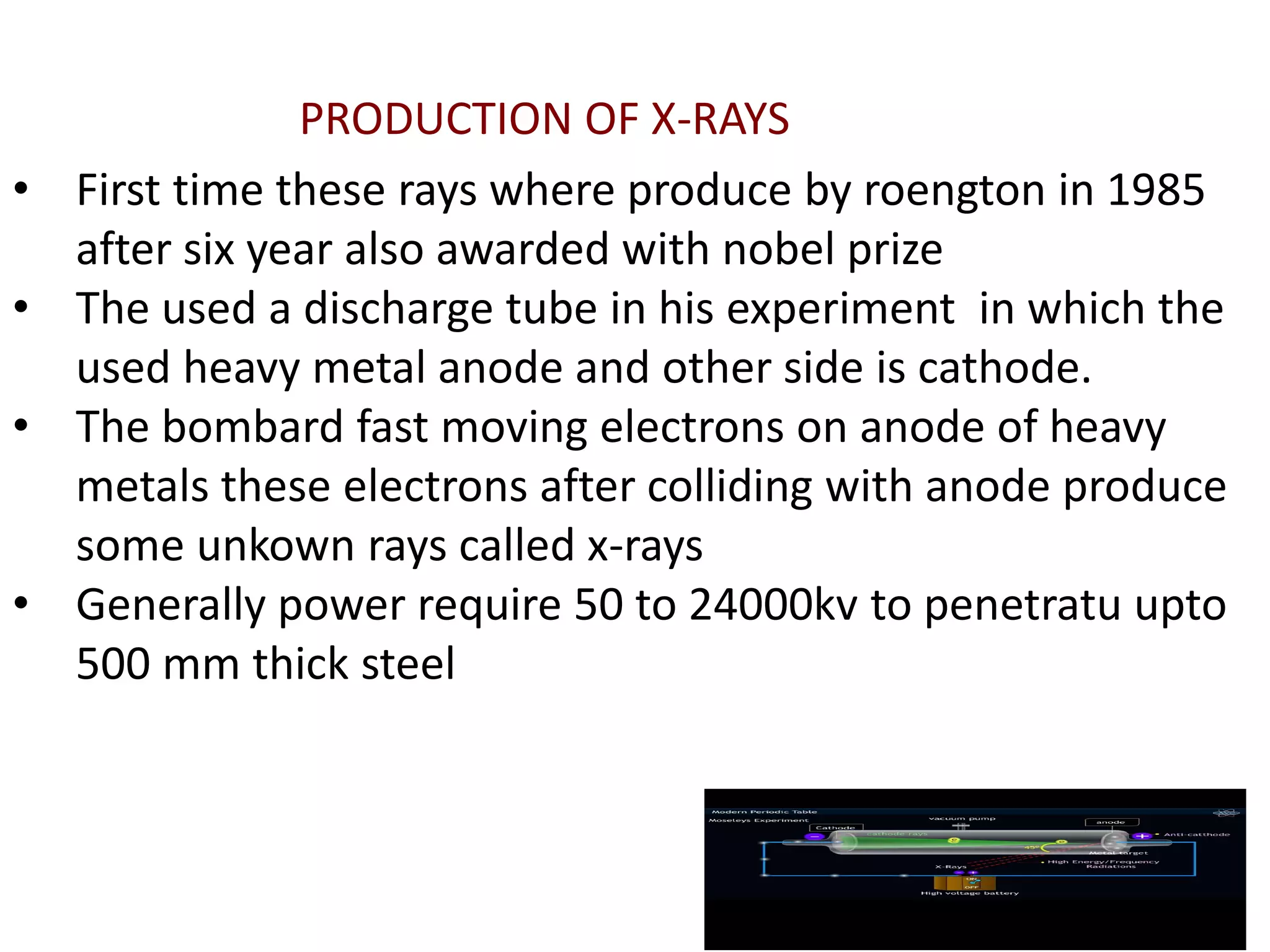
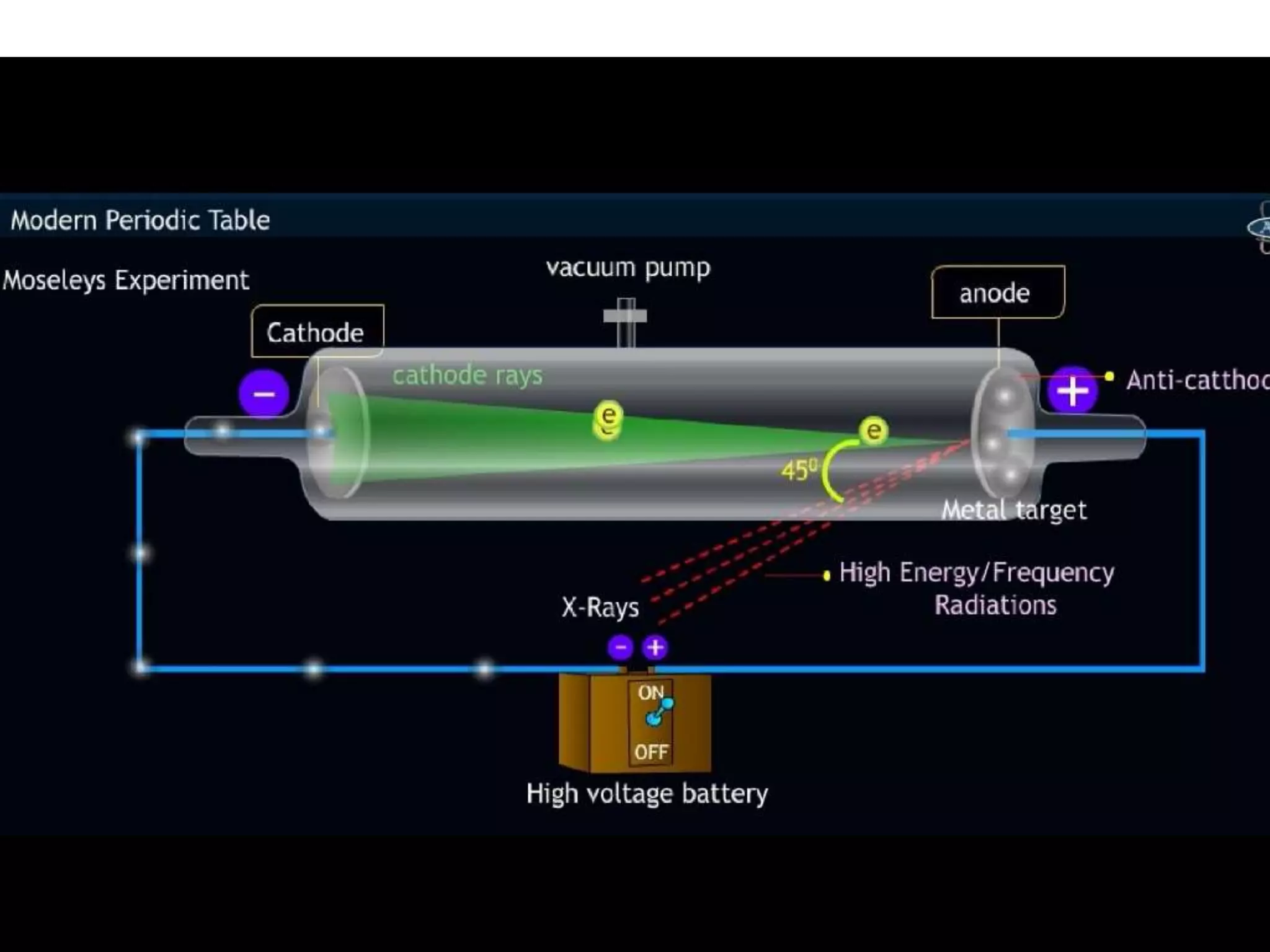
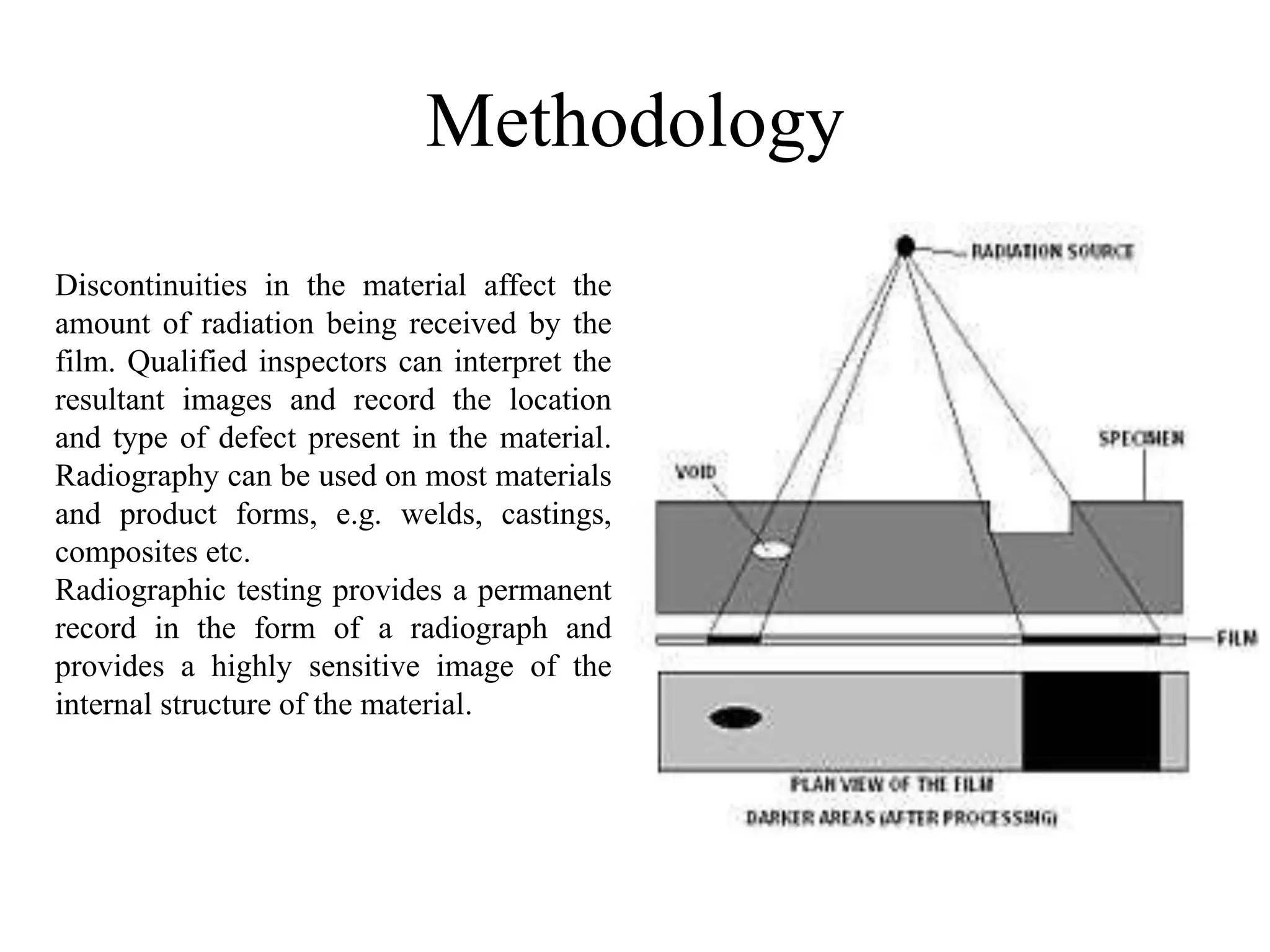
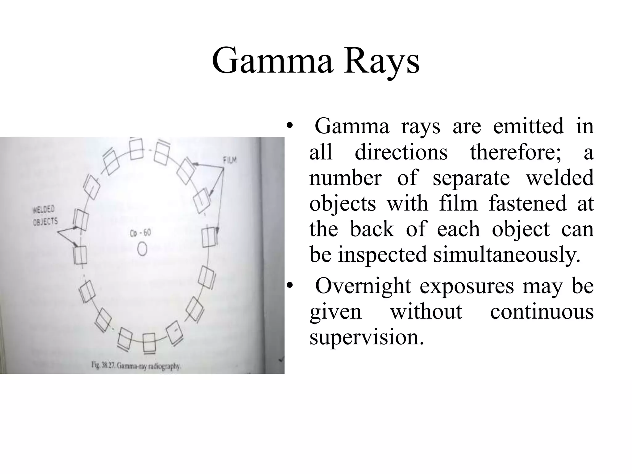
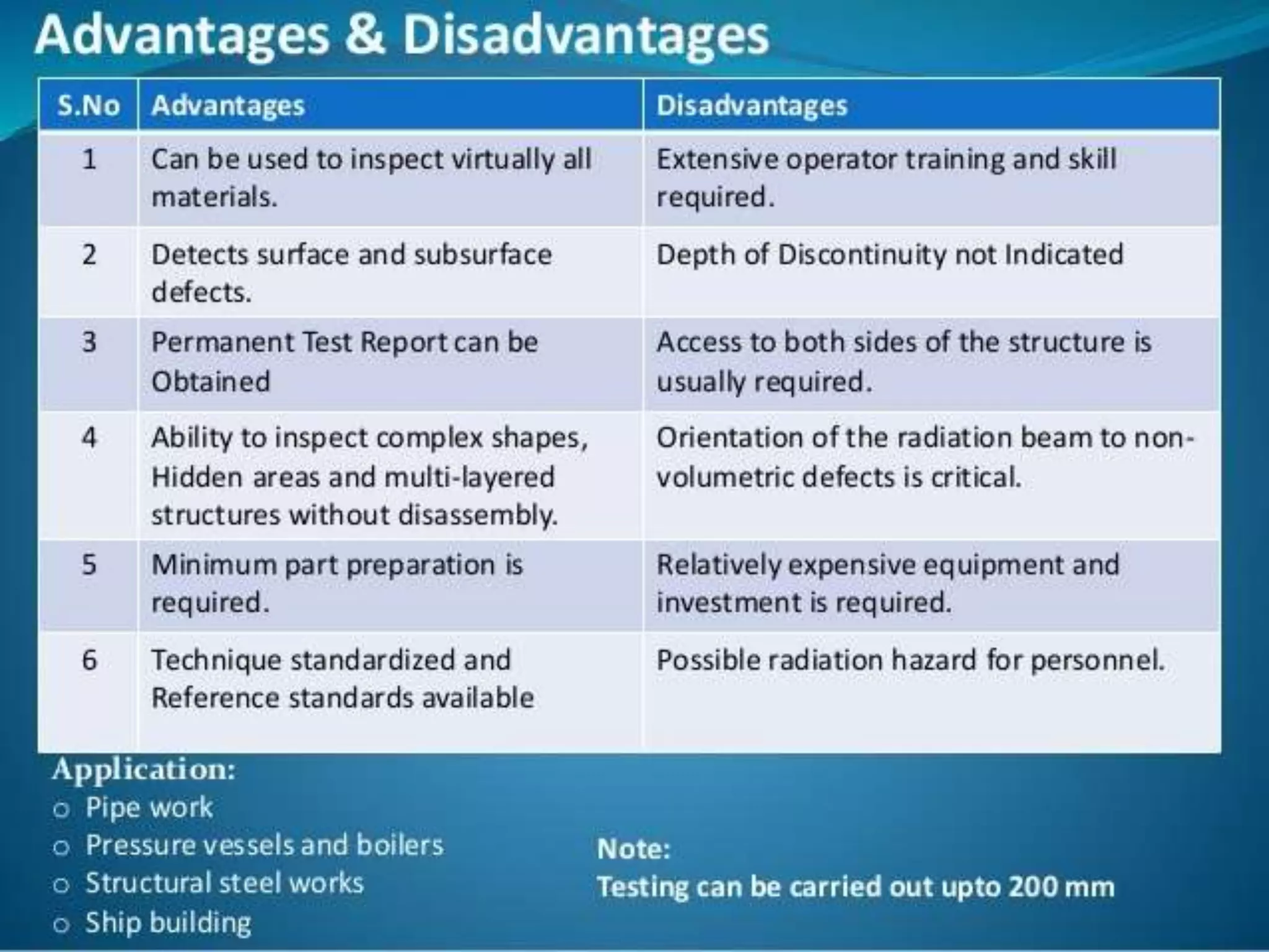
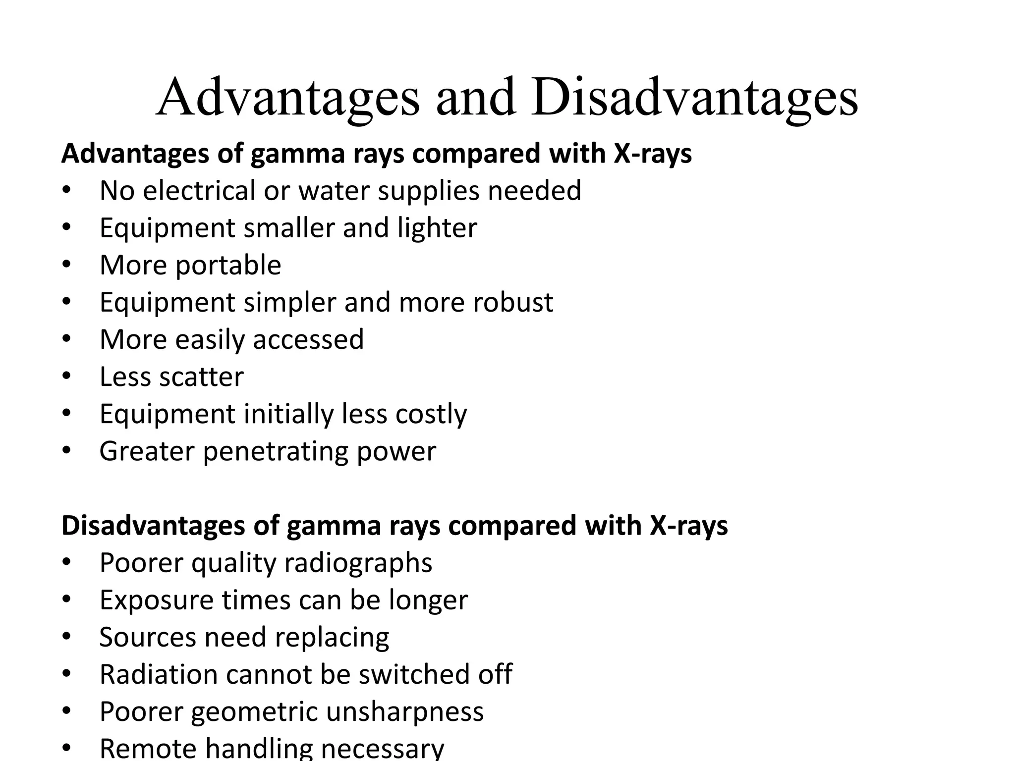
Radiographic Testing of welds
By -PAWAN KUMAR
PGWLF2150056
Radiography
• Radiography is one of the most useful non-
destructive tests which can be applied for
assessing the quality of the welds.
• It can be employed from minute electronic
welds to welds up to half meter thick in heavy
fabrications.
• It can detect cracks, porosity, blow holes, slag,
flux inclusions, lack of fusion and incomplete
penetration.
Characteristics of X and Gamma
Rays
• They penetrate matter depending on the radiation energy, material
density, and material thickness.
• They travel in straight lines.
• They travel at the velocity of light (186,262 miles per second,
344,472 km/sec).
• They cause fluorescence in some materials.
• They ionize matter and they expose film by ionization.
• Their energy is inversely proportional to their wavelength.
• They are invisible and undetectable by human senses. • They are not
particulate.
• They have no electrical charge.
• They have no rest mass or weight.
• Wave like properties expect refraction.
• Also not efected by electric or magnetic field.
• First time these rays where produce by roengton in 1985
after six year also awarded with nobel prize
• The used a discharge tube in his experiment in which the
used heavy metal anode and other side is cathode.
• The bombard fast moving electrons on anode of heavy
metals these electrons after colliding with anode produce
some unkown rays called x-rays
• Generally power require 50 to 24000kv to penetratu upto
500 mm thick steel
PRODUCTION OF X-RAYS
X-Rays
• Principle – Radiography by x-rays technique is
based upon exposing the components to short
wavelength X-rays (less than 0.001X 10⁻⁸ to
about 40X 10-8cm) from a suitable source such
as X- ray tube.
• These rays have high penetrating power, X-rays
operating at 400,000 volts can inspect steel
objects having thickness up to 62 mm.
X-Rays and Gamma Rays Radiations
X-Rays Generation
• X-rays are produced when electrons, traveling at high speed, collide
with matter. In the tube of a conventional static x-ray machine, an
incandescent filament supplies the electrons and forms the cathode
(negative electrode). The tube target is made the anode (positive
electrode). A high voltage potential is applied across the cathode and
anode providing an accelerating force to the electrons produced by
the filament. The sudden stopping of these fast moving electrons
near the surface of the target anode results in the generation of x-
rays. The higher the temperature of the filament, the greater is its
emission of electrons and the larger the resulting tube current. Other
conditions remaining the same, the x-ray output is proportional to
the tube current. Most of the energy applied to the tube is
transformed into heat at the focal spot on the target anode, with only
a small portion being transformed into x-rays.
X-Ray Tube
K - cathode (electron
source)
A - anode (target electrons)
C - cooling Water
UH - heating voltage
UA - accelerating voltage
X - X-radiation (X-rays)
ANIMATION
Methodology
• The method is based on the same principle as medical
radiography in a hospital. A piece of radiographic film is
placed on the remote side of the material under inspection and
radiation is then transmitted through from one side of the
material to the remote side where the radiographic film is
placed.
• The radiographic film detects the radiation and measures the
various quantities of radiation received over the entire surface
of the film. This film is then processed under dark room
conditions and the various degrees of radiation received by the
film are imaged by the display of different degrees of black
and white, this is termed the film density and is viewed on a
special light emitting device.
Methodology
Discontinuities in the material affect the
amount of radiation being received by the
film. Qualified inspectors can interpret the
resultant images and record the location
and type of defect present in the material.
Radiography can be used on most materials
and product forms, e.g. welds, castings,
composites etc.
Radiographic testing provides a permanent
record in the form of a radiograph and
provides a highly sensitive image of the
internal structure of the material.
Methodology
• The amount of energy absorbed by the object depends
on its thickness and density. Energy not absorbed by the
object causes exposure of the radiographic film. These
areas will be dark when the film is developed. Areas of
the film exposed to less energy remain lighter.
Therefore, areas of the object where the thickness has
been changed by discontinuities, such as porosity or
cracks, will appear as dark outlines on the film.
Inclusions of low density, such as slag, will appear as
dark areas on the film, while inclusions of high density,
such as tungsten, will appear as light areas.
Methodology
• All discontinuities are detected by viewing the
variations in the density of the processed film.
This permanent film record of weld quality is
relatively easy to interpret if personnel are
properly trained. Only qualified personnel should
conduct radiography and radiographic
interpretation because false readings can be
expensive for productivity, and also because
invisible X-ray and gamma radiation can be
hazardous.
Gamma Rays
• Gamma rays are emitted from the disintegrating nuclei of
radioactive substances of which the quality and intensity
of the radiation cannot be controlled by the user.
• Radium and its salts decomposes at a constant rate, giving
out gamma rays which are of much shorter wavelength
and have more penetrating power than ordinary x-rays.
• Cobalt 60 an isotope is more convenient and economical
as compare to Radium is also used.
• Most cobalt 60 sources are cylindrical, with dimensions
of 3X3 to 6 mm and sealed in an appropriate container or
capsule.
Gamma Rays
• Gamma rays are emitted in
all directions therefore; a
number of separate welded
objects with film fastened at
the back of each object can
be inspected simultaneously.
• Overnight exposures may be
given without continuous
supervision.
Advantages and Disadvantages
Advantages of gamma rays compared with X-rays
• No electrical or water supplies needed
• Equipment smaller and lighter
• More portable
• Equipment simpler and more robust
• More easily accessed
• Less scatter
• Equipment initially less costly
• Greater penetrating power
Disadvantages of gamma rays compared with X-rays
• Poorer quality radiographs
• Exposure times can be longer
• Sources need replacing
• Radiation cannot be switched off
• Poorer geometric unsharpness
• Remote handling necessary
THANKS

Radiographic testing of welds

  • 1.
    Radiographic Testing ofwelds By -PAWAN KUMAR PGWLF2150056
  • 2.
    Radiography • Radiography isone of the most useful non- destructive tests which can be applied for assessing the quality of the welds. • It can be employed from minute electronic welds to welds up to half meter thick in heavy fabrications. • It can detect cracks, porosity, blow holes, slag, flux inclusions, lack of fusion and incomplete penetration.
  • 3.
    Characteristics of Xand Gamma Rays • They penetrate matter depending on the radiation energy, material density, and material thickness. • They travel in straight lines. • They travel at the velocity of light (186,262 miles per second, 344,472 km/sec). • They cause fluorescence in some materials. • They ionize matter and they expose film by ionization. • Their energy is inversely proportional to their wavelength. • They are invisible and undetectable by human senses. • They are not particulate. • They have no electrical charge. • They have no rest mass or weight. • Wave like properties expect refraction. • Also not efected by electric or magnetic field.
  • 4.
    • First timethese rays where produce by roengton in 1985 after six year also awarded with nobel prize • The used a discharge tube in his experiment in which the used heavy metal anode and other side is cathode. • The bombard fast moving electrons on anode of heavy metals these electrons after colliding with anode produce some unkown rays called x-rays • Generally power require 50 to 24000kv to penetratu upto 500 mm thick steel PRODUCTION OF X-RAYS
  • 6.
    X-Rays • Principle –Radiography by x-rays technique is based upon exposing the components to short wavelength X-rays (less than 0.001X 10⁻⁸ to about 40X 10-8cm) from a suitable source such as X- ray tube. • These rays have high penetrating power, X-rays operating at 400,000 volts can inspect steel objects having thickness up to 62 mm.
  • 8.
    X-Rays and GammaRays Radiations
  • 9.
    X-Rays Generation • X-raysare produced when electrons, traveling at high speed, collide with matter. In the tube of a conventional static x-ray machine, an incandescent filament supplies the electrons and forms the cathode (negative electrode). The tube target is made the anode (positive electrode). A high voltage potential is applied across the cathode and anode providing an accelerating force to the electrons produced by the filament. The sudden stopping of these fast moving electrons near the surface of the target anode results in the generation of x- rays. The higher the temperature of the filament, the greater is its emission of electrons and the larger the resulting tube current. Other conditions remaining the same, the x-ray output is proportional to the tube current. Most of the energy applied to the tube is transformed into heat at the focal spot on the target anode, with only a small portion being transformed into x-rays.
  • 10.
    X-Ray Tube K -cathode (electron source) A - anode (target electrons) C - cooling Water UH - heating voltage UA - accelerating voltage X - X-radiation (X-rays)
  • 11.
  • 12.
    Methodology • The methodis based on the same principle as medical radiography in a hospital. A piece of radiographic film is placed on the remote side of the material under inspection and radiation is then transmitted through from one side of the material to the remote side where the radiographic film is placed. • The radiographic film detects the radiation and measures the various quantities of radiation received over the entire surface of the film. This film is then processed under dark room conditions and the various degrees of radiation received by the film are imaged by the display of different degrees of black and white, this is termed the film density and is viewed on a special light emitting device.
  • 13.
    Methodology Discontinuities in thematerial affect the amount of radiation being received by the film. Qualified inspectors can interpret the resultant images and record the location and type of defect present in the material. Radiography can be used on most materials and product forms, e.g. welds, castings, composites etc. Radiographic testing provides a permanent record in the form of a radiograph and provides a highly sensitive image of the internal structure of the material.
  • 14.
    Methodology • The amountof energy absorbed by the object depends on its thickness and density. Energy not absorbed by the object causes exposure of the radiographic film. These areas will be dark when the film is developed. Areas of the film exposed to less energy remain lighter. Therefore, areas of the object where the thickness has been changed by discontinuities, such as porosity or cracks, will appear as dark outlines on the film. Inclusions of low density, such as slag, will appear as dark areas on the film, while inclusions of high density, such as tungsten, will appear as light areas.
  • 15.
    Methodology • All discontinuitiesare detected by viewing the variations in the density of the processed film. This permanent film record of weld quality is relatively easy to interpret if personnel are properly trained. Only qualified personnel should conduct radiography and radiographic interpretation because false readings can be expensive for productivity, and also because invisible X-ray and gamma radiation can be hazardous.
  • 16.
    Gamma Rays • Gammarays are emitted from the disintegrating nuclei of radioactive substances of which the quality and intensity of the radiation cannot be controlled by the user. • Radium and its salts decomposes at a constant rate, giving out gamma rays which are of much shorter wavelength and have more penetrating power than ordinary x-rays. • Cobalt 60 an isotope is more convenient and economical as compare to Radium is also used. • Most cobalt 60 sources are cylindrical, with dimensions of 3X3 to 6 mm and sealed in an appropriate container or capsule.
  • 17.
    Gamma Rays • Gammarays are emitted in all directions therefore; a number of separate welded objects with film fastened at the back of each object can be inspected simultaneously. • Overnight exposures may be given without continuous supervision.
  • 27.
    Advantages and Disadvantages Advantagesof gamma rays compared with X-rays • No electrical or water supplies needed • Equipment smaller and lighter • More portable • Equipment simpler and more robust • More easily accessed • Less scatter • Equipment initially less costly • Greater penetrating power Disadvantages of gamma rays compared with X-rays • Poorer quality radiographs • Exposure times can be longer • Sources need replacing • Radiation cannot be switched off • Poorer geometric unsharpness • Remote handling necessary
  • 28.