COURSE OBJECTIVES
•This Course Presents The Fundamental Knowledge & Skills In The
Theory, Design & Implementation Of RF & Microwave Systems.
• Upon completion of this course, Students Will Be Able To
Understand:
• The Basics Of Microwave Engineering;
• Key Aspects Of Microwave Circuits, TX’ssion Lines, Antennas &
Propagation Of Radio Waves;
• The Techniques To Solve Real Problems In Microwave System
Design & Implementation.
4.
TABLE OF CONTENTS
CHAPTER ONE: OVERVIEW OF RF AND MICROWAVE TECHNOLOGY
• Development history of RF & microwave Technology,
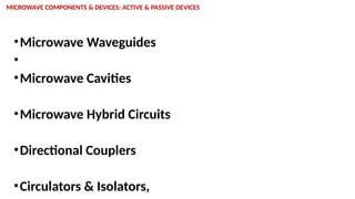
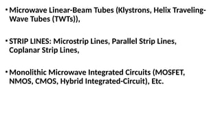
• Microwave components & devices: active & passive devices.
CHAPTER TWO: MICROWAVE DIODES AND MICROWAVE BIPOLAR
TRANSISTOR
• 2.1 p-i-n Diodes, Schottky Diodes, Varactor Diodes & Tunnel Diodes
Components & Their Applications in microwave circuits.
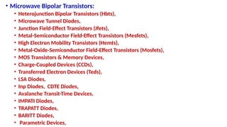
• Bipolar Transistors & Heterojunction Bipolar Transistors Components &
• Their Applications in microwave circuits
CHAPTER ONE: OVERVIEWOF RF & MICROWAVE TECHNOLOGY
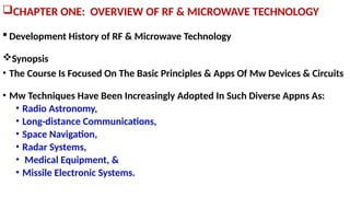
Development History of RF & Microwave Technology
Synopsis
• The Course Is Focused On The Basic Principles & Apps Of Mw Devices & Circuits
• Mw Techniques Have Been Increasingly Adopted In Such Diverse Appns As:
• Radio Astronomy,
• Long-distance Communications,
• Space Navigation,
• Radar Systems,
• Medical Equipment, &
• Missile Electronic Systems.
17.
Synopsis Cont’d
•As AResult Of The Accelerating Rate Of Growth Of Mw
Technology In Research & Industry:
•Students Who Are Preparing Themselves For, &
Electronics Engineers Who Are Working In, The Mw
Area,
•Are Faced With The Need To Understand The
Theoretical, Experimental Design & Analysis Of
Microwave Devices & Circuits.
18.
MICROWAVE FREQUENCIES
• TheTerm Mw Freqs Is Generally Used For Those Wavelengths Measured In
Centimeters, Roughly From 30 cm To 1 mm (1 To 300 Ghz).
• However, Microwave Really Indicates The Wavelengths In The Micron Ranges.
• This Means Mw Freqs Are Up To Infrared & Visible-light Regions.
• Mw Freqs Refer To Those From 1 Ghz Up To 106 Ghz.
• The Microwave Band Designation Was Derived From World War II Radar
Security Considerations.
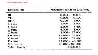
• The IEEE recommended new microwave band designations shown Below
MICROWAVE DEVICES
• InThe Late 1930s It Became Evident That As The Wavelength Approached
The Physical
• Dimensions Of The Vacuum Tubes, The Electron Transit Angle,
Interelectrode Capacitance & Inductance Appeared To Limit The Operation
Of Vacuum Tubes In Mw Freqs.
• In 1935 A. A. Heil & 0. Heil Suggested That Me Voltages Be Generated By
Using Transit-time Effects Together With Lumped Tuned Circuits.
• In 1939 W. C. Hahn And G. F. Metcalf Proposed A Theory Of Velocity
Modulation For Microwave Tubes.
21.
•Four Months LaterR. H. Varian And S. F. Varian Described
A Two-cavity Klystron Amplifier & Oscillator By Using
Velocity Modulation.
•In 1944 R. Kompfner Invented The Helix-type Traveling-
wave Tube (TWT).
•Ever Since Then, The Concept Of Mw Tubes Has Deviated
From That Of Conventional Vacuum Tubes;
•As A Result Of The Appn Of New Principles In The
Amplification & Generation Of Microwave Energy.
22.
•Historically Mw Generation& Amplification Were
Accomplished By Means Of Velocity-modulation Theory.
•In The Past 3 Decades, However,
• Microwave Solid-state Devices-such As Tunnel Diodes, Gunn
Diodes, Transferred Electron Devices (Teds), And Avalanche
Transit-time Devices Have Been Developed To Perform These
Functions.
•The Conception & Subsequent Development Of Teds &
Avalanche Transit-time Devices Were Among The
Outstanding Technical Achievements.
23.
• B. K.Ridley And T. B. Watkins In 1961 And C. Hilsum In 1962
Independently Predicted That;
• “The Transferred Electron Effect Would Occur In GaAs” (Gallium
Arsenide).
• In 1963 J. B. Gunn Reported His "Gunn Effect."
• The Common Characteristic Of All Mw Solid State Devices Is The Negative
Resistance That Can Be Used For Mw Oscillation & Amplification.
• The Progress Of Avalanche Transit-time Devices Has Been So Swift
That:
• Today, They Are Firmly Established As One Of The Most Important Classes
Of Mw Solid-state Devices.
24.
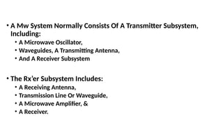
• A MwSystem Normally Consists Of A Transmitter Subsystem,
Including:
• A Microwave Oscillator,
• Waveguides, A Transmitting Antenna,
• And A Receiver Subsystem
• The Rx’er Subsystem Includes:
• A Receiving Antenna,
• Transmission Line Or Waveguide,
• A Microwave Amplifier, &
• A Receiver.
•In Order ToDesign A Mw System & Conduct A Proper Test
Of It, An Adequate Knowledge Of The Components Involved
Is Essential.
•Besides Mw Devices, This Course Thus Describes Mw
Components, Such As:
• Resonators,
• Cavities,
• Microstrip Lines, Hybrids, And
• Microwave Integrated Circuits.