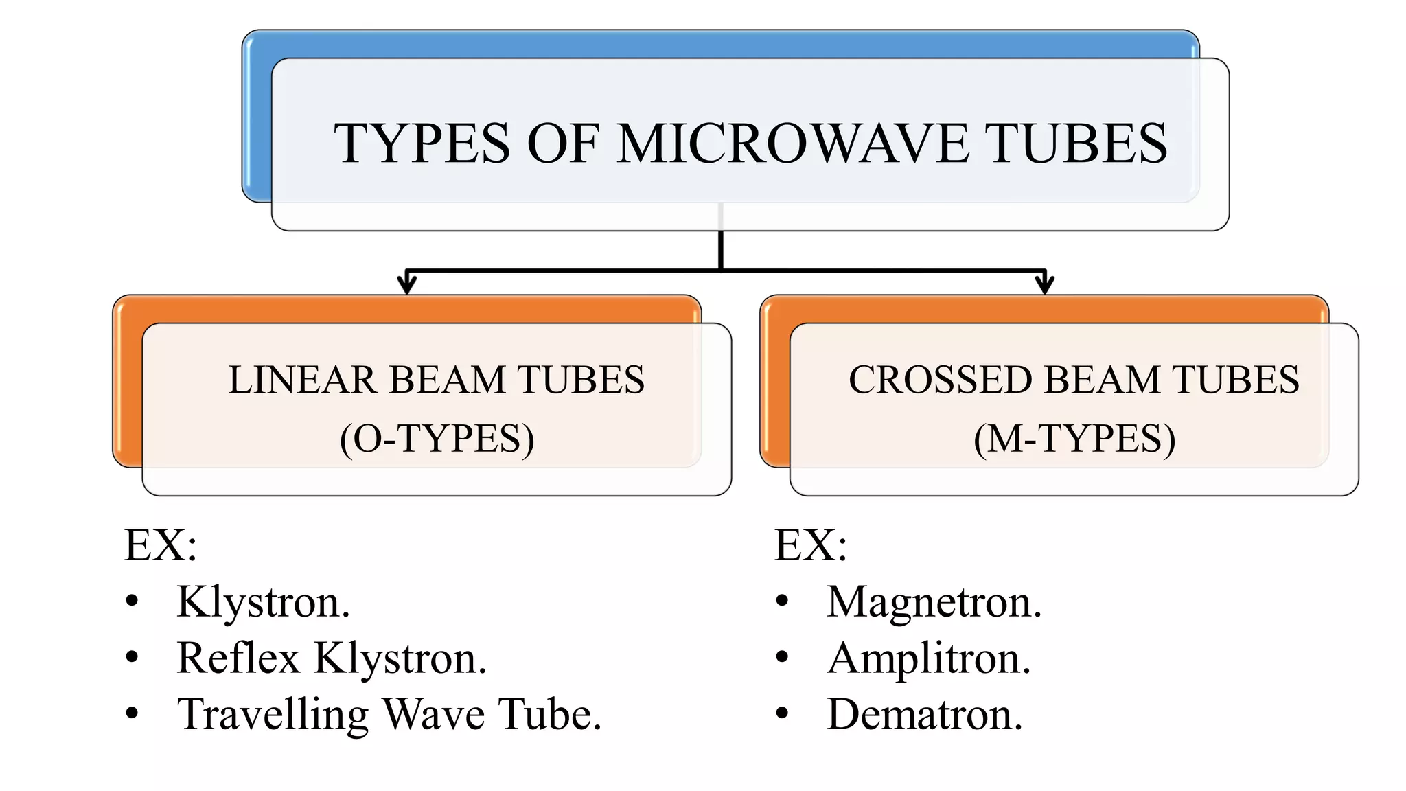
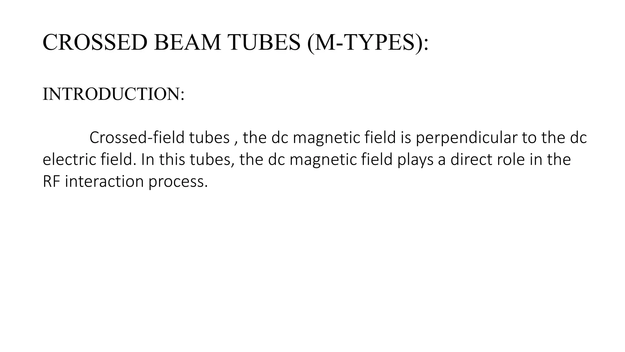
CONTENTS
Introduction.
Types of Micro Wave Tubes.
Micro Wave Tubes.
Nature of Propagation Constants.
Gain Considerations of TWT.
M-type Tubes Introduction.
• Magnetrons.
Cross-field Effect.
• Microwave tubes are electron guns for generating beam tubes. It produce
microwaves.
• A microwave tube generates and amplifies higher frequencies in
the microwave range(300MHz-300GHz) of frequency spectrum.
INTRODUCTION
• A microwave tube works on the principle of
velocity modulation. A velocity modulation
principle generally avoids, the problem of
frequency limitation, that often occurs in
microwave tubes.
TYPES OF MICROWAVE TUBES
LINEAR BEAM TUBES
(O-TYPES)
CROSSED BEAM TUBES
(M-TYPES)
EX:
• Klystron.
• Reflex Klystron.
• Travelling Wave Tube.
EX:
• Magnetron.
• Amplitron.
• Dematron.
MICROWAVE TUBES:
• In linear beam tubes like “Klystron (or) Travelling wave
tube (TWT)”, the dc Magnetic field parallel to the dc
Electric field is used to focus the electron beam.
• Crossed-field tubes , the dc magnetic field is perpendicular
to the dc electric field. In this tubes, the dc magnetic field
plays a direct role in the RF interaction process.
FIG: TRAVELLING WAVE TUBE WITH
POWER SUPPLY
NATURE OF 4 PROPAGATION CONSTANTS:
By solving the electronic and circuit equations at the same time the
wave modes of the helix TWT are determined. Thus the values of four
propagation constants g are given by
𝜸 𝟏 = −𝜷 𝒆 𝑪
𝟑
𝟐
+ 𝒋𝜷 𝒆 𝟏 +
𝑪
𝟐
; 𝜸 𝟐 = 𝜷 𝒆 𝑪
𝟑
𝟐
+ 𝒋𝜷 𝒆 𝟏 +
𝑪
𝟐
𝜸 𝟑 = 𝒋𝜷 𝒆 𝟏 − 𝑪 ; 𝜸 𝟒 = −𝒋𝜷 𝒆 𝟏 −
𝑪 𝟑
𝟒
These 4 propagation constants represent four different modes.
Where γ1 = Forward wave and its Amplitude grows exponentially.
γ2= Forward wave and its Amplitude decays exponentially.
γ3= Forward wave and its Amplitude remains constant.
γ4 = Backward wave and No change in amplitude.
• Above the structure is perfectly matched ,so that there is no Backward
traveling wave.
• Even though there is a Reflected wave from the output end of the tube
traveling, Backward travelling wave is toward the input end, the attenuator
placed around the centre of the tube. It is used to set the reflected wave is
minimum or zero level.
• Thus the total circuit voltage is the sum of three forward voltages
corresponding to the three forward traveling waves. This is equivalent to
GAIN CONSIDERATION:
V(z)=𝑽 𝟏 𝒆−𝜸 𝟏 𝒛
+ 𝑽 𝟐 𝒆−𝜸 𝟐 𝒛
+𝑽 𝟑 𝒆−𝜸 𝟑 𝒛
= σ 𝒏=𝟏
𝟑
𝑽 𝒏 𝒆−γ 𝒏 𝒁 1
The input current can be given by,
𝒊(𝒛) = − ෍
𝒏=𝟏
𝟑
𝑰 𝟎
𝟐𝑽 𝟎 𝑪 𝟐
𝑽 𝒏
𝜹 𝒏
𝟐
𝒆−𝜸 𝒏 𝒛
To determine the amplification of the growing wave, the input reference
point is set at z = 0 and the output reference point is taken at z = l.
𝒗 𝟏(𝒛) = ෍
𝒏=𝟏
𝟑
𝒋
𝒗 𝟎
𝟐𝑽 𝟎 𝑪
𝑽 𝒏
δ 𝒏
𝒆−𝜸 𝒏 𝒛
The input fluctuating component of velocity of the total wave
2
3
It follows that at z = 0 the voltage, current, and velocity at the input point are
given by
𝒗 𝟏 𝟎 = −𝒋
𝑰 𝟎
𝟐𝑽 𝟎 𝑪
𝑽 𝟏
𝜹 𝟏
𝟐
+
𝑽 𝟐
𝜹 𝟐
𝟐
+
𝑽 𝟑
𝜹 𝟑
𝟐
V(0) = 𝑽 𝟏 + 𝑽 𝟐+𝑽 𝟑
𝒊(𝟎) = − ෍
𝒏=𝟏
𝟑
𝑰 𝟎
𝟐𝑽 𝟎 𝑪 𝟐
𝑽 𝒏
𝜹 𝒏
𝟐 =
−𝑰 𝟎
𝟐𝑽 𝟎 𝑪 𝟐
𝑽 𝟏
𝜹 𝟏
𝟐 +
𝑽 𝟐
𝜹 𝟐
𝟐 +
𝑽 𝟑
𝜹 𝟑
𝟐
Eq (2):-
Eq (3):-
The simultaneous solution of Eqs.1,2 & 3 with 𝒊(0) = 0 and 𝒗 𝟏(0) = 0 is
𝑽 𝟏 = 𝑽 𝟐= 𝑽 𝟑=
𝑽(𝟎)
𝟑
The amplitude of the output voltage is then given by
V(l)=
𝑉(0)
3
𝑒( 3  𝑁𝐶)
The output power gain in decibels is defined as
𝐴 𝑝=10𝑙𝑜𝑔
𝑉(l)
𝑉(0)
2
= −9.54 + 47.3𝑁𝐶 𝑑𝐵
where NC is a numerical number.
4
5
The output power gain shown in Eq. (5) indicates an initial loss at the
circuit input of 9.54 dB .
This loss results from the fact that the input voltage splits into three
waves of equal magnitude and the growing wave voltage is only one-third the
total input voltage.
CROSSED BEAM TUBES (M-TYPES):
INTRODUCTION:
Crossed-field tubes , the dc magnetic field is perpendicular to the dc
electric field. In this tubes, the dc magnetic field plays a direct role in the
RF interaction process.
Re-entrant
Magnetron
Forward wave Backward wave
Crossed-field tubes
(M-types)
Maser effectNon-resonantResonant
Standing wave
Re-entrant Re-entrantNon-Reentrant Non-Reentrant
FWCFA Dematron Amplitron Carsinotron
CROSS-FIELD EFFECT:
• In a Crossed-field tube , the electrons emitted by the cathode are
accelerated by the electric field and gain velocity , but the greater their
velocity , the more their path is bent by the magnetic field.
• If an RF field is applied to the anode circuit, those electrons entering the
circuit during retarding field are decelerated and give up some of their
kinetic energy to the RF field.
• Consequently , their velocity is decreased and these slower electrons will
then travel the dc electric field far enough to regain essentially the same
velocity as before.
• Those electrons entering the circuit during the accelerating field are
accelerated by means of receiving enough energy from the RF field and are
returned back towards the cathode. This back bombardment of the
cathode produces heat in the cathode and decreases the operational
efficiency.
MAGNETRON:
The magnetron is a high-powered vacuum tube that works as a self-
excited microwave oscillator. Crossed electron and magnetic fields are used
in the magnetron to produce the high-power output required in radar
equipment.
Fig: Magnetron (2M291-M32QVL) for
Microwave for Model DMY-OTHERS
IMP Panasonic
CROSSED-FIELD AMPLIFIER (CFA):
A crossed-field amplifier (CFA) is a specialized vacuum tube, first
introduced in the mid-1950s and frequently used as a microwave amplifier in
very-high-power transmitters.
Fig: CROSSED-FIELD
AMPLIFIER (CFA)
It can be used as broadband
amplifier and as oscillator. It solves the
low efficiency problem of TWT without
comprising on the bandwidth.
The efficiencies of up to 80% can
be achieved using CFA device.
REFERENCE BOOKS
Microwave-devices-and-circuits-samuel-liao
Introduction of travelling wave & magnetrons

Introduction of travelling wave & magnetrons

  • 2.
    CONTENTS Introduction. Types of MicroWave Tubes. Micro Wave Tubes. Nature of Propagation Constants. Gain Considerations of TWT. M-type Tubes Introduction. • Magnetrons. Cross-field Effect.
  • 3.
    • Microwave tubesare electron guns for generating beam tubes. It produce microwaves. • A microwave tube generates and amplifies higher frequencies in the microwave range(300MHz-300GHz) of frequency spectrum. INTRODUCTION • A microwave tube works on the principle of velocity modulation. A velocity modulation principle generally avoids, the problem of frequency limitation, that often occurs in microwave tubes.
  • 4.
    TYPES OF MICROWAVETUBES LINEAR BEAM TUBES (O-TYPES) CROSSED BEAM TUBES (M-TYPES) EX: • Klystron. • Reflex Klystron. • Travelling Wave Tube. EX: • Magnetron. • Amplitron. • Dematron.
  • 5.
    MICROWAVE TUBES: • Inlinear beam tubes like “Klystron (or) Travelling wave tube (TWT)”, the dc Magnetic field parallel to the dc Electric field is used to focus the electron beam. • Crossed-field tubes , the dc magnetic field is perpendicular to the dc electric field. In this tubes, the dc magnetic field plays a direct role in the RF interaction process.
  • 6.
    FIG: TRAVELLING WAVETUBE WITH POWER SUPPLY
  • 7.
    NATURE OF 4PROPAGATION CONSTANTS: By solving the electronic and circuit equations at the same time the wave modes of the helix TWT are determined. Thus the values of four propagation constants g are given by 𝜸 𝟏 = −𝜷 𝒆 𝑪 𝟑 𝟐 + 𝒋𝜷 𝒆 𝟏 + 𝑪 𝟐 ; 𝜸 𝟐 = 𝜷 𝒆 𝑪 𝟑 𝟐 + 𝒋𝜷 𝒆 𝟏 + 𝑪 𝟐 𝜸 𝟑 = 𝒋𝜷 𝒆 𝟏 − 𝑪 ; 𝜸 𝟒 = −𝒋𝜷 𝒆 𝟏 − 𝑪 𝟑 𝟒
  • 8.
    These 4 propagationconstants represent four different modes. Where γ1 = Forward wave and its Amplitude grows exponentially. γ2= Forward wave and its Amplitude decays exponentially. γ3= Forward wave and its Amplitude remains constant. γ4 = Backward wave and No change in amplitude.
  • 9.
    • Above thestructure is perfectly matched ,so that there is no Backward traveling wave. • Even though there is a Reflected wave from the output end of the tube traveling, Backward travelling wave is toward the input end, the attenuator placed around the centre of the tube. It is used to set the reflected wave is minimum or zero level. • Thus the total circuit voltage is the sum of three forward voltages corresponding to the three forward traveling waves. This is equivalent to GAIN CONSIDERATION: V(z)=𝑽 𝟏 𝒆−𝜸 𝟏 𝒛 + 𝑽 𝟐 𝒆−𝜸 𝟐 𝒛 +𝑽 𝟑 𝒆−𝜸 𝟑 𝒛 = σ 𝒏=𝟏 𝟑 𝑽 𝒏 𝒆−γ 𝒏 𝒁 1
  • 10.
    The input currentcan be given by, 𝒊(𝒛) = − ෍ 𝒏=𝟏 𝟑 𝑰 𝟎 𝟐𝑽 𝟎 𝑪 𝟐 𝑽 𝒏 𝜹 𝒏 𝟐 𝒆−𝜸 𝒏 𝒛 To determine the amplification of the growing wave, the input reference point is set at z = 0 and the output reference point is taken at z = l. 𝒗 𝟏(𝒛) = ෍ 𝒏=𝟏 𝟑 𝒋 𝒗 𝟎 𝟐𝑽 𝟎 𝑪 𝑽 𝒏 δ 𝒏 𝒆−𝜸 𝒏 𝒛 The input fluctuating component of velocity of the total wave 2 3
  • 11.
    It follows thatat z = 0 the voltage, current, and velocity at the input point are given by 𝒗 𝟏 𝟎 = −𝒋 𝑰 𝟎 𝟐𝑽 𝟎 𝑪 𝑽 𝟏 𝜹 𝟏 𝟐 + 𝑽 𝟐 𝜹 𝟐 𝟐 + 𝑽 𝟑 𝜹 𝟑 𝟐 V(0) = 𝑽 𝟏 + 𝑽 𝟐+𝑽 𝟑 𝒊(𝟎) = − ෍ 𝒏=𝟏 𝟑 𝑰 𝟎 𝟐𝑽 𝟎 𝑪 𝟐 𝑽 𝒏 𝜹 𝒏 𝟐 = −𝑰 𝟎 𝟐𝑽 𝟎 𝑪 𝟐 𝑽 𝟏 𝜹 𝟏 𝟐 + 𝑽 𝟐 𝜹 𝟐 𝟐 + 𝑽 𝟑 𝜹 𝟑 𝟐 Eq (2):- Eq (3):-
  • 12.
    The simultaneous solutionof Eqs.1,2 & 3 with 𝒊(0) = 0 and 𝒗 𝟏(0) = 0 is 𝑽 𝟏 = 𝑽 𝟐= 𝑽 𝟑= 𝑽(𝟎) 𝟑 The amplitude of the output voltage is then given by V(l)= 𝑉(0) 3 𝑒( 3  𝑁𝐶) The output power gain in decibels is defined as 𝐴 𝑝=10𝑙𝑜𝑔 𝑉(l) 𝑉(0) 2 = −9.54 + 47.3𝑁𝐶 𝑑𝐵 where NC is a numerical number. 4 5
  • 13.
    The output powergain shown in Eq. (5) indicates an initial loss at the circuit input of 9.54 dB . This loss results from the fact that the input voltage splits into three waves of equal magnitude and the growing wave voltage is only one-third the total input voltage.
  • 14.
    CROSSED BEAM TUBES(M-TYPES): INTRODUCTION: Crossed-field tubes , the dc magnetic field is perpendicular to the dc electric field. In this tubes, the dc magnetic field plays a direct role in the RF interaction process.
  • 15.
    Re-entrant Magnetron Forward wave Backwardwave Crossed-field tubes (M-types) Maser effectNon-resonantResonant Standing wave Re-entrant Re-entrantNon-Reentrant Non-Reentrant FWCFA Dematron Amplitron Carsinotron
  • 16.
    CROSS-FIELD EFFECT: • Ina Crossed-field tube , the electrons emitted by the cathode are accelerated by the electric field and gain velocity , but the greater their velocity , the more their path is bent by the magnetic field. • If an RF field is applied to the anode circuit, those electrons entering the circuit during retarding field are decelerated and give up some of their kinetic energy to the RF field. • Consequently , their velocity is decreased and these slower electrons will then travel the dc electric field far enough to regain essentially the same velocity as before.
  • 17.
    • Those electronsentering the circuit during the accelerating field are accelerated by means of receiving enough energy from the RF field and are returned back towards the cathode. This back bombardment of the cathode produces heat in the cathode and decreases the operational efficiency.
  • 18.
    MAGNETRON: The magnetron isa high-powered vacuum tube that works as a self- excited microwave oscillator. Crossed electron and magnetic fields are used in the magnetron to produce the high-power output required in radar equipment. Fig: Magnetron (2M291-M32QVL) for Microwave for Model DMY-OTHERS IMP Panasonic
  • 19.
    CROSSED-FIELD AMPLIFIER (CFA): Acrossed-field amplifier (CFA) is a specialized vacuum tube, first introduced in the mid-1950s and frequently used as a microwave amplifier in very-high-power transmitters. Fig: CROSSED-FIELD AMPLIFIER (CFA) It can be used as broadband amplifier and as oscillator. It solves the low efficiency problem of TWT without comprising on the bandwidth. The efficiencies of up to 80% can be achieved using CFA device.
  • 20.