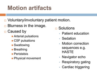
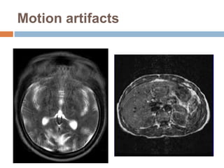
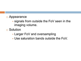
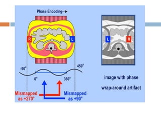
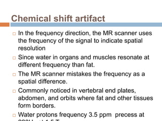
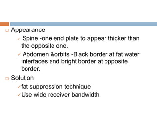
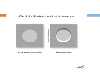
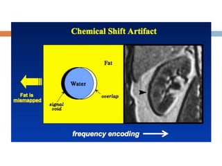
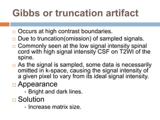
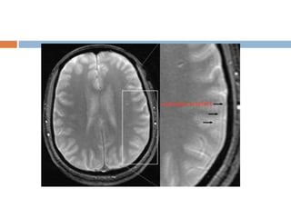
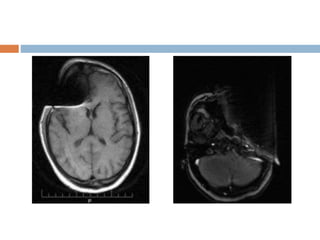
MRI ARTIFACTS
 What is an artifact??
 An image artifact is a structure not normally
present.
 But visible as a result of a limitation or
malfunction in the hardware or software in the
MRI device.
 Some affect the quality of the MRI exam while
others do not affect the diagnostic quality but
may be confused with pathology.
 The knowledge of MRI artifacts and noise
producing factors is important for continuing
maintenance of image quality.
 Sources of artifacts
Hardware issues
Software problems
Physiological phenomena
Physical limitations
 Types of artifacts
 Ghosting/Motion artifacts
 Aliasing
 Chemical shift
Gibbs or truncation
 Magnetic Susceptibility
 Zipper artifact/Straight Lines
 Shading
Cross Excitation and Cross Talk
 Parallel Imaging
 Black boundary
 Entry slice phenomenon
 Field inhomogenity
 Slice overlapping
Magic angle
Moire fringes
RF overflow
Eddy current artifacts
Center point artifact
Motion artifacts
 Voluntary/involuntary patient motion.
 Blurness in the image.
 Caused by
 Arterial pulsations
 CSF pulsations
 Swallowing
 Breathing
 Peristalsis
 Physical movement
 Solutions
 Patient education
 Sedation
 Motion correction
sequences e.g.
HASTE
 Navigator echo
 Respiratory gating
 Cardiac triggering
Motion artifacts
Aliasing artifact or
wraparound
 It occurs when the dimensions of the body part
being imaged exceed the FoV.
 The part beyond the FoV is projected to the
other side of the image.
 It is caused by under sampling in the phase
encoded direction.
 Choosing an FoV that is smaller than the area
imaged leads to wraparound or aliasing
artifacts.
 Appearance
 signals from outside the FoV seen in the
imaging volume.
 Solution
 Larger FoV and oversampling
 Use saturation bands outside the FoV.
Chemical shift artifact
 In the frequency direction, the MR scanner uses
the frequency of the signal to indicate spatial
resolution
 Since water in organs and muscles resonate at
different frequency than fat.
 The MR scanner mistakes the frequency as a
spatial difference.
 Commonly noticed in vertebral end plates,
abdomen, and orbits where fat and other tissues
form borders.
 Water protons frequency 3.5 ppm precess at
 Appearance
 Spine -one end plate to appear thicker than
the opposite one.
 Abdomen &orbits -Black border at fat water
interfaces and bright border at opposite
border.
 Solution
fat suppression technique
Use wide receiver bandwidth
Gibbs or truncation artifact
 Occurs at high contrast boundaries.
 Due to truncation(omission) of sampled signals.
 Commonly seen at the low signal intensity spinal
cord with high signal intensity CSF on T2WI of the
spine.
 As the signal is sampled, some data is necessarily
omitted in k-space, causing the signal intensity of
a given pixel to vary from its ideal signal intensity.
 Appearance
 Bright and dark lines.
 Solution
 Increase matrix size.
Magnetic suscepbility artifact
 Distortion in the MR image especially seen in
while imaging with metallic orthopedic hardware
or dental work.
 Magnetic field inhomogenetics introduced by the
metallic object in to homogeneous magnetic
field.
 Greater at high magnetic field strength.
 Worst with long TE and gradient echo
sequences.
 Appearance
Bright and dark areas
 Solution
Larger receiver bandwidth
Gradient echo and echo planar sequences
should be avoided.
The use of echo spin particularly fast spin
echo sequences should be considered.
Zipper artifact
 Most of them related to hardware or software
problems.
 RF from some radio transmitters will cause
zipper that are oriented perpendicular to
frequency direction.
 Occur in either frequency or phase encoding
directions.
 Solutions
MR scanner room is shut down.
Remove all electric devices from patient.
Field inhomogenity
 Contribute to signal non uniformity.
 May arise from RF coil construction or standing
wave effects.
 When the RF is shorter than the dimensions of
the anatomic structures examined standing
waves may result.
 Leads to inhomogeneous fat suppression.
 Solution
 Shimming –allow precise control of overall
homogeneity of RF field.
 Use STIR for Fat Sat.
 Coil- use volume coils, allow space between body
and coil.
 Dielectric –use phased array coils.
RF overflow/Shading artifact
 Non uniform, washed out appearance in an
image.
 Occurs when the signal received from the patient
is too intense to be digitized by analog to digital
converter.
 Auto prescanning usually adjusts the receiver
gain.
 Post processing methods also existing but may
be time consuming.
Central Point/Parallel Imaging
Artifact
 A focal dot of increased or decreased signal in
the center of the image.
 Caused by constant offset of the DC voltage in
the amplifiers.
 Solution
 Requires calibration.
 Maintain a constant temperature.
Black Boundary artifact
 Artificially created black line located at water fat
interfaces.
 This results in sharp delineation of the muscle
fat boundary that is sometimes visually
appealing but not an anatomical structure.
 Occurs at TE when the fat and water spins
located in the same pixel are out of phase,
cancelling each others signal.
 Particularly noticeable in GRE sequences.
 Both in frequency and phase directions.
 Remedy
Use phase TE’s
Fat suppression technique
Increase matrix size and bandwidth.
Entry slice phenomenon
 When unsaturated spins in blood first enter in to
a slice or slices.
 Characterized by bright signal in a blood vessel
at the first slice.
 Confused with thrombosis.
 Gradient echo flow techniques to differentiate.
 Solution
 Use spatial saturation bands before the first and
after the last.
Slice overlapping
 Loss of signal due to multi slice, multi angle
acquisition or imperfect slice profile.
 Mechanism : Spin saturation.
 If slices at different angles cross, then spins that
have previously excited, could be excited again.
 Mostly seen in spine imaging e.g. L4-L5 or L5-
S1.
 Appearance
 Band of signal loss crossing horizontally in the
image, usually posteriorly.
 Solution
 Continuous imaging
 Increase slice gap.
Magic angle artifact
 Seen most frequently in tendons and ligaments that
are oriented at a 55 degree to main magnetic field.
 Normally dipolar interaction between water
molecules in ligaments are strong.
 Which implies that T2 relaxation is very fast leading
to signal loss.
 Dipolar interaction go to zero.
 Solution
 Lengthen TE
 Use T1 weighted sequences since T1 relaxation is
unaffected by this.
Moire fringes
 An interference pattern most commonly when
doing gradient echo images.
 One cause is aliasing of one side of the body to
the other results in superimposition.
 Can also be caused by receiver picking up a
stimulated echo.
 Similar to the effect of looking through two
window screens.
 Solution
 Improve shimming
Eddy current artifact
 Varying magnetic field induces electric current
which distort gradient waveforms.
 When diffusion gradient applied, change in
magnetic field creates electric current .
 Such current creates smaller magnetic field that
Bo.
 Modern gradient coils equipped with active
shielding to avoid these effects of electric
conduction.
 Solution
 Shielding gradients.
 A distorted gradient
waveform is used
Spike artifact
 Caused by one bad data point k-space.
 Shows one data point in k-space, which is out of
ordinary.
 Diagonal lines in the image.
 Solution
Repeat the scan
Annefact artifact
 Due to anatomy within the active volume of the
coil, but outside the Fov.
 Signals from such region give rise to ghost
imaging in the phase encoding direction.
 Most commonly in sagittal spine imaging
especially in T and L spines.
 Always turn off the coils which is not in use.
MRI Artifacts

MRI Artifacts

  • 1.
  • 2.
     What isan artifact??  An image artifact is a structure not normally present.  But visible as a result of a limitation or malfunction in the hardware or software in the MRI device.  Some affect the quality of the MRI exam while others do not affect the diagnostic quality but may be confused with pathology.  The knowledge of MRI artifacts and noise producing factors is important for continuing maintenance of image quality.
  • 3.
     Sources ofartifacts Hardware issues Software problems Physiological phenomena Physical limitations
  • 4.
     Types ofartifacts  Ghosting/Motion artifacts  Aliasing  Chemical shift Gibbs or truncation  Magnetic Susceptibility  Zipper artifact/Straight Lines  Shading Cross Excitation and Cross Talk  Parallel Imaging
  • 5.
     Black boundary Entry slice phenomenon  Field inhomogenity  Slice overlapping Magic angle Moire fringes RF overflow Eddy current artifacts Center point artifact
  • 6.
    Motion artifacts  Voluntary/involuntarypatient motion.  Blurness in the image.  Caused by  Arterial pulsations  CSF pulsations  Swallowing  Breathing  Peristalsis  Physical movement  Solutions  Patient education  Sedation  Motion correction sequences e.g. HASTE  Navigator echo  Respiratory gating  Cardiac triggering
  • 7.
  • 8.
    Aliasing artifact or wraparound It occurs when the dimensions of the body part being imaged exceed the FoV.  The part beyond the FoV is projected to the other side of the image.  It is caused by under sampling in the phase encoded direction.  Choosing an FoV that is smaller than the area imaged leads to wraparound or aliasing artifacts.
  • 9.
     Appearance  signalsfrom outside the FoV seen in the imaging volume.  Solution  Larger FoV and oversampling  Use saturation bands outside the FoV.
  • 12.
    Chemical shift artifact In the frequency direction, the MR scanner uses the frequency of the signal to indicate spatial resolution  Since water in organs and muscles resonate at different frequency than fat.  The MR scanner mistakes the frequency as a spatial difference.  Commonly noticed in vertebral end plates, abdomen, and orbits where fat and other tissues form borders.  Water protons frequency 3.5 ppm precess at
  • 13.
     Appearance  Spine-one end plate to appear thicker than the opposite one.  Abdomen &orbits -Black border at fat water interfaces and bright border at opposite border.  Solution fat suppression technique Use wide receiver bandwidth
  • 16.
    Gibbs or truncationartifact  Occurs at high contrast boundaries.  Due to truncation(omission) of sampled signals.  Commonly seen at the low signal intensity spinal cord with high signal intensity CSF on T2WI of the spine.  As the signal is sampled, some data is necessarily omitted in k-space, causing the signal intensity of a given pixel to vary from its ideal signal intensity.  Appearance  Bright and dark lines.  Solution  Increase matrix size.
  • 18.
    Magnetic suscepbility artifact Distortion in the MR image especially seen in while imaging with metallic orthopedic hardware or dental work.  Magnetic field inhomogenetics introduced by the metallic object in to homogeneous magnetic field.  Greater at high magnetic field strength.  Worst with long TE and gradient echo sequences.
  • 19.
     Appearance Bright anddark areas  Solution Larger receiver bandwidth Gradient echo and echo planar sequences should be avoided. The use of echo spin particularly fast spin echo sequences should be considered.
  • 21.
    Zipper artifact  Mostof them related to hardware or software problems.  RF from some radio transmitters will cause zipper that are oriented perpendicular to frequency direction.  Occur in either frequency or phase encoding directions.  Solutions MR scanner room is shut down. Remove all electric devices from patient.
  • 23.
    Field inhomogenity  Contributeto signal non uniformity.  May arise from RF coil construction or standing wave effects.  When the RF is shorter than the dimensions of the anatomic structures examined standing waves may result.  Leads to inhomogeneous fat suppression.
  • 24.
     Solution  Shimming–allow precise control of overall homogeneity of RF field.  Use STIR for Fat Sat.  Coil- use volume coils, allow space between body and coil.  Dielectric –use phased array coils.
  • 26.
    RF overflow/Shading artifact Non uniform, washed out appearance in an image.  Occurs when the signal received from the patient is too intense to be digitized by analog to digital converter.  Auto prescanning usually adjusts the receiver gain.  Post processing methods also existing but may be time consuming.
  • 28.
    Central Point/Parallel Imaging Artifact A focal dot of increased or decreased signal in the center of the image.  Caused by constant offset of the DC voltage in the amplifiers.  Solution  Requires calibration.  Maintain a constant temperature.
  • 30.
    Black Boundary artifact Artificially created black line located at water fat interfaces.  This results in sharp delineation of the muscle fat boundary that is sometimes visually appealing but not an anatomical structure.  Occurs at TE when the fat and water spins located in the same pixel are out of phase, cancelling each others signal.  Particularly noticeable in GRE sequences.  Both in frequency and phase directions.
  • 31.
     Remedy Use phaseTE’s Fat suppression technique Increase matrix size and bandwidth.
  • 32.
    Entry slice phenomenon When unsaturated spins in blood first enter in to a slice or slices.  Characterized by bright signal in a blood vessel at the first slice.  Confused with thrombosis.  Gradient echo flow techniques to differentiate.  Solution  Use spatial saturation bands before the first and after the last.
  • 34.
    Slice overlapping  Lossof signal due to multi slice, multi angle acquisition or imperfect slice profile.  Mechanism : Spin saturation.  If slices at different angles cross, then spins that have previously excited, could be excited again.  Mostly seen in spine imaging e.g. L4-L5 or L5- S1.
  • 35.
     Appearance  Bandof signal loss crossing horizontally in the image, usually posteriorly.  Solution  Continuous imaging  Increase slice gap.
  • 37.
    Magic angle artifact Seen most frequently in tendons and ligaments that are oriented at a 55 degree to main magnetic field.  Normally dipolar interaction between water molecules in ligaments are strong.  Which implies that T2 relaxation is very fast leading to signal loss.  Dipolar interaction go to zero.  Solution  Lengthen TE  Use T1 weighted sequences since T1 relaxation is unaffected by this.
  • 39.
    Moire fringes  Aninterference pattern most commonly when doing gradient echo images.  One cause is aliasing of one side of the body to the other results in superimposition.  Can also be caused by receiver picking up a stimulated echo.  Similar to the effect of looking through two window screens.
  • 40.
  • 41.
    Eddy current artifact Varying magnetic field induces electric current which distort gradient waveforms.  When diffusion gradient applied, change in magnetic field creates electric current .  Such current creates smaller magnetic field that Bo.  Modern gradient coils equipped with active shielding to avoid these effects of electric conduction.
  • 42.
     Solution  Shieldinggradients.  A distorted gradient waveform is used
  • 43.
    Spike artifact  Causedby one bad data point k-space.  Shows one data point in k-space, which is out of ordinary.  Diagonal lines in the image.  Solution Repeat the scan
  • 45.
    Annefact artifact  Dueto anatomy within the active volume of the coil, but outside the Fov.  Signals from such region give rise to ghost imaging in the phase encoding direction.  Most commonly in sagittal spine imaging especially in T and L spines.  Always turn off the coils which is not in use.