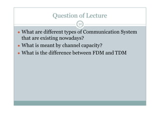
EE344 Communication Systems
Course Outline
5
● Basic definitions
● Modulation and de-modulation techniques: amplitude,
angle, pulse modulation, digital modulation techniques
● Information theory
● Error detection and correction
● Multiplexing techniques
● Noise and its effects on signal transmission
● BER performance of various modulation techniques
under noisy environment.
● Overview of other communication Systems(PSTN, Radio
&TV, Cellular, Satellite, Fiber and Cable transmission)
● Revision and Problem Discussion
Course Contents
6
● Amplitude Modulation Systems: Frequency translation, recovery of base signal, amplitude
modulation, maximum allowable modulation, square law demodulator, spectrum of AM signal
modulators, balanced modulator, single sideband, vestigial sideband and compatible single sideband
system, multiplexing.
● Frequency Modulation Systems: Angle modulation, phase and frequency modulation,
relationship between phase and frequency modulation, spectrum of FM signal effect of modulation
index on bandwidth. EF generation and detection methods, limiters, frequency multiplication.
● Pulse Modulation Systems: Sampling theorem, low pass signals, pulse amplitude pulse width and
pulse position modulation, bandwidth requirements, spectra, cross talk. methods of generation and
detection of PAM, PVVM signals, pulse code modulation, quantization and commanding. PCM
systems, equalization, synchronous and asynchronous PCM systems, delta modulation, phase shift
keying, differential phase shift keying, frequency shiftkeying.
● Noise: Mathematical representation, effect of filtering, response of narrow band filter to noise,
superposition of noise, probability density, noise in am, FM system noise calculations, shot noise,
thermal noise, noise temperature, noise bandwidth, noise figure, noise figure and equivalent noise in
cascaded system, signal to noiseratio.
● Information Theory and Coding: Discrete messages, concept of amount of information, average
information, entropy information rate, Shannon’s theorem, channel capacity, relation between band
width and S/N ration. Coding: Parity check coding, error correction elementary system.
● Digital Modulation: ASK< PSK< FASK< OOK etc
HEC Recommended Books
7
● B. P. Lathi, “Modern Digital and Analog Communication Systems.
● Leon W. Couch, “Digital and Analog Communication Systems.
● John G. Proakis and Masoud Salehi, “Communication Systems.
● Principles of Communication Systems, Taub Schilling McGraw Hill,
Latest edition.
● Communication Systems by Bruce Carlson, Latest edition.
● Analog and Digital Communication, Simon Haykin, Latest edition.
Outline: Lecture 1
8
● Communication Systems its fundamentals and components
● Base band and modulated signal
● Analog and digital transmission.
● Signal, Effectiveness of signal, Information, Data, Sender, Receiver, Noise,
Guided and Unguided medium
● Unidirectional and Bi-directional communication
● Overview of system types: point-point, point-multipoint, broadcast systems;
● Modes of transmitting Information
● Simplex, half & full duplex, baseband & pass band
● Multiplexing
● Modulation
● Mathematical modeling of signals, time and frequency domain concepts,
spectral density, signal to Noise Ratio, Channel Capacity
● Need for modulation Fourier Series and Transforms Review.
9
● Let’s START…
Basic Qs.
10
● What is information?
And
● ‘How information flows from one point to another at
the most basic level?’
information
11
● Information Types: voice, text, images, video, music, digital data.
● Communication Systems: radio/TV broadcasting, PSTN, cellular phones,
computer networks, satellite systems, Bluetooth.
● Communication systems send information electronically over
communication channels.
● Many different types of systems which convey many different types of
information.
● Design challenges include hardware, system and network issues.
● Goal of the communication system is to recreate original information at the
receiver with the highest possible fidelity.
Information Representation
12
● Communication systems convert information into a format
appropriate for the communications channel, typically an
electromagnetic wave.
● Analog communication systems convert (modulate) analog
information signals into modulated signals, which are also
analog.
● Digital communication systems convert information in the
form of bits into digital signals.
● Computers and digital devices generate information as bits.
Analog information signals can be converted to bits by
quantizing and digitizing.
Type of Information
13
● Analog signals: voice, music, temperature readings,
etc.
● Analog or digital signals: video and images
● Bits: text, computer data, etc.
● Analog signals can be converted into bits by
sampling and quantizing.
Basic Communication System
14
● Transmitter
● Channel
● Receiver
Block Diagram
15
Detailed Communication System
16
Block Diagram
17
● Source encoder: converts the source or input message into an analog signal
or bits called the message signal.
• Transmitter: converts the message signal into a modulated signal in a format
suitable for transmission over the channel.
● Channel: Introduces distortion and random noise. Linear channels have
output y(t) =x(t) h(t)+n(t), where x(t) is the transmitted (modulated)
signal, n(t) is the random noise, h(t) is the channel impulse response, and *
denotes convolution.
● Receiver: Receiver extracts the original message signal or bits from the
channel output signal.
● Source Decoder: Converts the message signal or bits back into the format of
the original message.
(contd.)
18
Source, Transducer, baseband signal
19
Noise Addition
20
21
Signal to Noise Ratio
22
Transmitting Station
23
1. Generates a RF carrier
2.Combines it with the baseband signal into a RF signal
through modulation
3. Performs additional operations
» E.g. analog-to-digital conversion, formatting, coding,
spreading, adding additional messages/ characteristics
such as error-control, authentication, or location
information
4.Radiates the resultant signal in the form of a modulated
radio wave
● Shortly - it maps the original message into the radio-
wave signal launched at the transmitting antenna
Propagation process
24
•Transforms, or maps, the radio-wave signal
launched by the transmitter into the incident
radio wave at the receiver antenna
• The propagation mapping involves extra variables
(e.g. distance, latency), additional radio waves (e.g.
reflected wave, waves originated in the
environment), random uncertainty (e.g. noise,
fading) and distortions
Receiver
25
Filters the incident signals : rejects
unwanted signals and extract the
wanted signal
– The receiver’s response defines a
solid “window” in the signal
hyperspace
2. Recovers the original message
through reversing the transmitter
operations (demodulation,
decoding, de-spreading, etc.),
• compensating propagation
transformations, and correcting
transmission distortions
• Shortly: Maps the incident signals
into the recovered message
Analog and Digital Signals
26
• Analog signals: varies over a continuous range. Most
signals occurring in nature are analog.
• Digital signals: value takes on only a finite set of
values (staircase functions).
• Binary signals: value takes on just two values
(corresponding to “0”s and “1”s of bits).
• A bit time T is the amount of time required to send
one bit. Data rate R = 1/T bits per second (bps).
Signal Power
27
Performance Metrics
28
● Performance metric for analog systems is fidelity:
want m(t) = ˆm(t).
● Performance metric for digital systems is data rate
(R bps) and probability of bit error (Pb )
Data Rate Tradeoff
29
● The data rate in digital communications defines the number
of bits per second that are transmitted.
● For a probability of bit error (Pb) of 50%, the data rate canbe
infinite.
● For channels without distortion or noise, the data rate can be
infinite with Pb = 0.
● For a fixed data rate, Pb depends on signal and noise power
and the channel characteristics.
● For a given system, increasing data rate typically increases Pb.
Shannon Capacity
30
● Defines the maximum data rate at which information can be
transferred over a channel without errors.
● For a channel with received signal power S, additive white
noise with received noise power N, and bandwidth B:
● C = B log2(1 + S/N) bps.
● Shannon theory does not tell you how to design real
communication systems.
● Shannon theory predicted a maximum modem speed of 32
Kbps in 1949. Today we have 56 Kbps modems. (Problemwas
accuracy of mathematical models, not the theory itself.)
Classification and representation of signals,
31
● Frequency Domain
● Time Domain
Contd.
● Simplex
● Half & full duplex
● Baseband
● Pass band
Simplex
● Simplex communication is permanent unidirectional communication.
Some of the very first serial connections between computers were
simplex connections. For example, mainframes sent data to a printer
and never checked to see if the printer was available or if the document
printed properly since that was a human job.
● Simplex links are built so that the transmitter (the one talking) sends a
signal and it's up to the receiving device (the listener) to figure out what
was sent and to correctly do what it was told. No traffic is possible in
the other direction across the same connection.
Half Duplex
A half duplex link can communicate in only one direction, at a time.
Two way communication is possible, but not simultaneously. Walkie-
talkies and CB radios sort of mimic this behavior in that you cannot
hear the other person if you are talking.
Half-duplex connections are more common over electrical links. Since
electricity won't flow unless you have a complete loop of wire, you need
two pieces of wire between the two systems to form the loop. The first
wire is used to transmit, the second wire is referred to as a common
ground. Thus, the flow of electricity can be reversed over the
transmitting wire, thereby reversing the path of communication.
Electricity cannot flow in both directions simultaneously, so the link is
half-duplex.
Full Duplex
Full duplex communication is two-way communication achieved over a
physical link that has the ability to communicate in both directions
simultaneously. With most electrical, fiber optic, two-way radio and
satellite links, this is usually achieved with more than one physical
connection. Your telephone line contains two wires, one for transmit,
the other for receive. This means you and your friend can both talk and
listen at the same time.
Baseband
The baseband is defined as a transmission signal that contains more
than just a single frequency from 0 Hz to the highest frequency
component.
In essence, the baseband is the original signal that is intended to be
transmitted. However, this baseband frequency, when transmitted
towards its target, can easily be slowed down or can pick up noise and
distortion, which is why the original baseband signal must be
transmitted into radio frequency. Radio frequency, however, also is at
risk for transmission problems, creating the need for a band-pass filter.
Passband
The passband is the output of a band-pass filter. It is a signal
that corresponds to the settings of the band-pass filter. While
baseband is the original signal, passband is the filtered signal.
Passband is more technically defined as the portion of the
spectrum between limiting frequencies with minimum relative
loss or maximum relative gain. Given the earlier example, a
radio tuner set at 107.5 MHz will allow only 107.5 MHz to pass
through. Anything below or above 107.5 MHz will be blocked
by the filter.
Returning Passband back to Baseband
After filtering, once the passband signal 107.5 MHz is received, the
circuitry of the radio demodulates and demultiplexes it so that a radio
listener receives, in some manner, the original or intended baseband
signal. While baseband is the original signal, passband is the filtered
signal that is eventually converted back to baseband.
Some short-distance systems do not have to modulate baseband to
higher frequencies before transmission. This is more common in lines
that do not require any form of modulation such as Ethernet. Without
the risk of interference or distortion, such systems do not need
baseband to be modulated and filtered to passband before reverting to
baseband.
Multiplexing
40
Multiplexing is the process of combining multiple signals
into one, in such a manner that each individual signal can
be retrieved at thedestination.
why?
Since multiple signals are occupying the channel, they need
to share the resource in some manner.
Types
× FDM
× TDM (Synchronous, Asynchronous)
× WDM
FDM
41
● Frequency-division multiplexing (FDM) is a form of signal multiplexing where multiple
baseband signals are modulated on different frequency carrier waves and added together to
create a composite signal
In many communication systems, a single, large frequency band is assigned to the system and is
shared among a group of users.
Examples of this type of system include:
1. A microwave transmission line connecting two sites over a long distance.
2.AM or FM radio broadcast bands, which are divided among many channels or stations. The
stations are selected with the radio dial.
The deriving of two or more simultaneous, continuous channels from a transmission medium
by assigning a separate portion of the available frequency spectrum to each of the individual
channels. (188)
The simultaneous transmission of multiple separate signals through a shared medium at the
transmitter, the separate signals into separable frequency bands, and adding those results
linearly either before transmission or within the medium. All the signals may be amplified,
conducted, translated in frequency and routed toward a destination as a single signal, resulting
in economies which are the motivation for multiplexing.
TDM
42
Time-Division Multiplexing
Time-Division Multiplexing (TDM) is a type of digital or analog multiplexing in which
two or more signals or bit streams are transferred apparently simultaneously as sub-
channels in one communication channel, but are physically taking turns on the channel.
The time domain is divided into several recurrent timeslots of fixed length, one for each
sub-channel.
Time-division multiplexing (TDM) is a method of putting multiple data streams in a
single signal by separating the signal into many segments, each having a very short
duration. Each individual data stream is reassembled at the receiving end based on the
timing.
Time division multiplexing (TDM) and has many applications, including wireline
telephone systems and some cellular telephone systems. The main reason to use TDM is
to take advantage of existing transmission lines.
TIME DIVISION MULTIPLEXING (TDM) allows multiple conversations to take place by
the sharing of medium or channel in time. A channel is allocated a the whole of the line
bandwidth for a specific period of time. This means that each subscriber is allocated a
time slot.
FDM and TDM
43
WDM
44
In fiber-optic communications, wavelength-
division multiplexing (WDM) is a technology
which multiplexes a number of optical carrier signals
onto a single optical fiber by using different
wavelengths (i.e. colours) of laser light. This
technique enables bidirectional communications
over one strand of fiber, as well as multiplication of
capacity.
Modulation
45
Carrier
46
Types of Modulation
47
● Modulation: Signal is transferred to high frequency for efficient transmission.
e=A sin(ɷt +ɸ)
e= instant value
A= maximum amplitude
ɷ=angular velocity=2*pi*f
t=time
ɸ=phase angle
● Three types of Modulation
 AM
 FM
 PM
● (FM+PM)= Angle Modulation
Note: Two basic types of Modulation i.e. Amplitude and Angle.
Modulation
48
Main Points
49
● There are two main formats of signals, analog and digital. Digital
signals are more robust to noise and interference.
● Analog signals can be converted into bits by sampling/quantizing.
● Communication systems modulate analog signals or bits for
transmission over a communications channel.
● The building blocks of a communication system are meant to
convert information into an electronic format for transmission, then
convert it back to its original format after reception.
● Design goals of transmitter (modulator) and receiver (demodulator)
are to mitigate impairments introduced by channel.
Question of Lecture
50
● What are different types of Communication System
that are existing nowadays?
● What is meant by channel capacity?
● What is the difference between FDM and TDM

Communication system

  • 1.
  • 2.
    Course Outline 5 ● Basicdefinitions ● Modulation and de-modulation techniques: amplitude, angle, pulse modulation, digital modulation techniques ● Information theory ● Error detection and correction ● Multiplexing techniques ● Noise and its effects on signal transmission ● BER performance of various modulation techniques under noisy environment. ● Overview of other communication Systems(PSTN, Radio &TV, Cellular, Satellite, Fiber and Cable transmission) ● Revision and Problem Discussion
  • 3.
    Course Contents 6 ● AmplitudeModulation Systems: Frequency translation, recovery of base signal, amplitude modulation, maximum allowable modulation, square law demodulator, spectrum of AM signal modulators, balanced modulator, single sideband, vestigial sideband and compatible single sideband system, multiplexing. ● Frequency Modulation Systems: Angle modulation, phase and frequency modulation, relationship between phase and frequency modulation, spectrum of FM signal effect of modulation index on bandwidth. EF generation and detection methods, limiters, frequency multiplication. ● Pulse Modulation Systems: Sampling theorem, low pass signals, pulse amplitude pulse width and pulse position modulation, bandwidth requirements, spectra, cross talk. methods of generation and detection of PAM, PVVM signals, pulse code modulation, quantization and commanding. PCM systems, equalization, synchronous and asynchronous PCM systems, delta modulation, phase shift keying, differential phase shift keying, frequency shiftkeying. ● Noise: Mathematical representation, effect of filtering, response of narrow band filter to noise, superposition of noise, probability density, noise in am, FM system noise calculations, shot noise, thermal noise, noise temperature, noise bandwidth, noise figure, noise figure and equivalent noise in cascaded system, signal to noiseratio. ● Information Theory and Coding: Discrete messages, concept of amount of information, average information, entropy information rate, Shannon’s theorem, channel capacity, relation between band width and S/N ration. Coding: Parity check coding, error correction elementary system. ● Digital Modulation: ASK< PSK< FASK< OOK etc
  • 4.
    HEC Recommended Books 7 ●B. P. Lathi, “Modern Digital and Analog Communication Systems. ● Leon W. Couch, “Digital and Analog Communication Systems. ● John G. Proakis and Masoud Salehi, “Communication Systems. ● Principles of Communication Systems, Taub Schilling McGraw Hill, Latest edition. ● Communication Systems by Bruce Carlson, Latest edition. ● Analog and Digital Communication, Simon Haykin, Latest edition.
  • 5.
    Outline: Lecture 1 8 ●Communication Systems its fundamentals and components ● Base band and modulated signal ● Analog and digital transmission. ● Signal, Effectiveness of signal, Information, Data, Sender, Receiver, Noise, Guided and Unguided medium ● Unidirectional and Bi-directional communication ● Overview of system types: point-point, point-multipoint, broadcast systems; ● Modes of transmitting Information ● Simplex, half & full duplex, baseband & pass band ● Multiplexing ● Modulation ● Mathematical modeling of signals, time and frequency domain concepts, spectral density, signal to Noise Ratio, Channel Capacity ● Need for modulation Fourier Series and Transforms Review.
  • 6.
  • 7.
    Basic Qs. 10 ● Whatis information? And ● ‘How information flows from one point to another at the most basic level?’
  • 8.
    information 11 ● Information Types:voice, text, images, video, music, digital data. ● Communication Systems: radio/TV broadcasting, PSTN, cellular phones, computer networks, satellite systems, Bluetooth. ● Communication systems send information electronically over communication channels. ● Many different types of systems which convey many different types of information. ● Design challenges include hardware, system and network issues. ● Goal of the communication system is to recreate original information at the receiver with the highest possible fidelity.
  • 9.
    Information Representation 12 ● Communicationsystems convert information into a format appropriate for the communications channel, typically an electromagnetic wave. ● Analog communication systems convert (modulate) analog information signals into modulated signals, which are also analog. ● Digital communication systems convert information in the form of bits into digital signals. ● Computers and digital devices generate information as bits. Analog information signals can be converted to bits by quantizing and digitizing.
  • 10.
    Type of Information 13 ●Analog signals: voice, music, temperature readings, etc. ● Analog or digital signals: video and images ● Bits: text, computer data, etc. ● Analog signals can be converted into bits by sampling and quantizing.
  • 11.
    Basic Communication System 14 ●Transmitter ● Channel ● Receiver
  • 12.
  • 13.
  • 14.
    Block Diagram 17 ● Sourceencoder: converts the source or input message into an analog signal or bits called the message signal. • Transmitter: converts the message signal into a modulated signal in a format suitable for transmission over the channel. ● Channel: Introduces distortion and random noise. Linear channels have output y(t) =x(t) h(t)+n(t), where x(t) is the transmitted (modulated) signal, n(t) is the random noise, h(t) is the channel impulse response, and * denotes convolution. ● Receiver: Receiver extracts the original message signal or bits from the channel output signal. ● Source Decoder: Converts the message signal or bits back into the format of the original message.
  • 15.
  • 16.
  • 17.
  • 18.
  • 19.
  • 20.
    Transmitting Station 23 1. Generatesa RF carrier 2.Combines it with the baseband signal into a RF signal through modulation 3. Performs additional operations » E.g. analog-to-digital conversion, formatting, coding, spreading, adding additional messages/ characteristics such as error-control, authentication, or location information 4.Radiates the resultant signal in the form of a modulated radio wave ● Shortly - it maps the original message into the radio- wave signal launched at the transmitting antenna
  • 21.
    Propagation process 24 •Transforms, ormaps, the radio-wave signal launched by the transmitter into the incident radio wave at the receiver antenna • The propagation mapping involves extra variables (e.g. distance, latency), additional radio waves (e.g. reflected wave, waves originated in the environment), random uncertainty (e.g. noise, fading) and distortions
  • 22.
    Receiver 25 Filters the incidentsignals : rejects unwanted signals and extract the wanted signal – The receiver’s response defines a solid “window” in the signal hyperspace 2. Recovers the original message through reversing the transmitter operations (demodulation, decoding, de-spreading, etc.), • compensating propagation transformations, and correcting transmission distortions • Shortly: Maps the incident signals into the recovered message
  • 23.
    Analog and DigitalSignals 26 • Analog signals: varies over a continuous range. Most signals occurring in nature are analog. • Digital signals: value takes on only a finite set of values (staircase functions). • Binary signals: value takes on just two values (corresponding to “0”s and “1”s of bits). • A bit time T is the amount of time required to send one bit. Data rate R = 1/T bits per second (bps).
  • 24.
  • 25.
    Performance Metrics 28 ● Performancemetric for analog systems is fidelity: want m(t) = ˆm(t). ● Performance metric for digital systems is data rate (R bps) and probability of bit error (Pb )
  • 26.
    Data Rate Tradeoff 29 ●The data rate in digital communications defines the number of bits per second that are transmitted. ● For a probability of bit error (Pb) of 50%, the data rate canbe infinite. ● For channels without distortion or noise, the data rate can be infinite with Pb = 0. ● For a fixed data rate, Pb depends on signal and noise power and the channel characteristics. ● For a given system, increasing data rate typically increases Pb.
  • 27.
    Shannon Capacity 30 ● Definesthe maximum data rate at which information can be transferred over a channel without errors. ● For a channel with received signal power S, additive white noise with received noise power N, and bandwidth B: ● C = B log2(1 + S/N) bps. ● Shannon theory does not tell you how to design real communication systems. ● Shannon theory predicted a maximum modem speed of 32 Kbps in 1949. Today we have 56 Kbps modems. (Problemwas accuracy of mathematical models, not the theory itself.)
  • 28.
    Classification and representationof signals, 31 ● Frequency Domain ● Time Domain
  • 29.
    Contd. ● Simplex ● Half& full duplex ● Baseband ● Pass band
  • 30.
    Simplex ● Simplex communicationis permanent unidirectional communication. Some of the very first serial connections between computers were simplex connections. For example, mainframes sent data to a printer and never checked to see if the printer was available or if the document printed properly since that was a human job. ● Simplex links are built so that the transmitter (the one talking) sends a signal and it's up to the receiving device (the listener) to figure out what was sent and to correctly do what it was told. No traffic is possible in the other direction across the same connection.
  • 31.
    Half Duplex A halfduplex link can communicate in only one direction, at a time. Two way communication is possible, but not simultaneously. Walkie- talkies and CB radios sort of mimic this behavior in that you cannot hear the other person if you are talking. Half-duplex connections are more common over electrical links. Since electricity won't flow unless you have a complete loop of wire, you need two pieces of wire between the two systems to form the loop. The first wire is used to transmit, the second wire is referred to as a common ground. Thus, the flow of electricity can be reversed over the transmitting wire, thereby reversing the path of communication. Electricity cannot flow in both directions simultaneously, so the link is half-duplex.
  • 32.
    Full Duplex Full duplexcommunication is two-way communication achieved over a physical link that has the ability to communicate in both directions simultaneously. With most electrical, fiber optic, two-way radio and satellite links, this is usually achieved with more than one physical connection. Your telephone line contains two wires, one for transmit, the other for receive. This means you and your friend can both talk and listen at the same time.
  • 34.
    Baseband The baseband isdefined as a transmission signal that contains more than just a single frequency from 0 Hz to the highest frequency component. In essence, the baseband is the original signal that is intended to be transmitted. However, this baseband frequency, when transmitted towards its target, can easily be slowed down or can pick up noise and distortion, which is why the original baseband signal must be transmitted into radio frequency. Radio frequency, however, also is at risk for transmission problems, creating the need for a band-pass filter.
  • 35.
    Passband The passband isthe output of a band-pass filter. It is a signal that corresponds to the settings of the band-pass filter. While baseband is the original signal, passband is the filtered signal. Passband is more technically defined as the portion of the spectrum between limiting frequencies with minimum relative loss or maximum relative gain. Given the earlier example, a radio tuner set at 107.5 MHz will allow only 107.5 MHz to pass through. Anything below or above 107.5 MHz will be blocked by the filter.
  • 36.
    Returning Passband backto Baseband After filtering, once the passband signal 107.5 MHz is received, the circuitry of the radio demodulates and demultiplexes it so that a radio listener receives, in some manner, the original or intended baseband signal. While baseband is the original signal, passband is the filtered signal that is eventually converted back to baseband. Some short-distance systems do not have to modulate baseband to higher frequencies before transmission. This is more common in lines that do not require any form of modulation such as Ethernet. Without the risk of interference or distortion, such systems do not need baseband to be modulated and filtered to passband before reverting to baseband.
  • 37.
    Multiplexing 40 Multiplexing is theprocess of combining multiple signals into one, in such a manner that each individual signal can be retrieved at thedestination. why? Since multiple signals are occupying the channel, they need to share the resource in some manner. Types × FDM × TDM (Synchronous, Asynchronous) × WDM
  • 38.
    FDM 41 ● Frequency-division multiplexing(FDM) is a form of signal multiplexing where multiple baseband signals are modulated on different frequency carrier waves and added together to create a composite signal In many communication systems, a single, large frequency band is assigned to the system and is shared among a group of users. Examples of this type of system include: 1. A microwave transmission line connecting two sites over a long distance. 2.AM or FM radio broadcast bands, which are divided among many channels or stations. The stations are selected with the radio dial. The deriving of two or more simultaneous, continuous channels from a transmission medium by assigning a separate portion of the available frequency spectrum to each of the individual channels. (188) The simultaneous transmission of multiple separate signals through a shared medium at the transmitter, the separate signals into separable frequency bands, and adding those results linearly either before transmission or within the medium. All the signals may be amplified, conducted, translated in frequency and routed toward a destination as a single signal, resulting in economies which are the motivation for multiplexing.
  • 39.
    TDM 42 Time-Division Multiplexing Time-Division Multiplexing(TDM) is a type of digital or analog multiplexing in which two or more signals or bit streams are transferred apparently simultaneously as sub- channels in one communication channel, but are physically taking turns on the channel. The time domain is divided into several recurrent timeslots of fixed length, one for each sub-channel. Time-division multiplexing (TDM) is a method of putting multiple data streams in a single signal by separating the signal into many segments, each having a very short duration. Each individual data stream is reassembled at the receiving end based on the timing. Time division multiplexing (TDM) and has many applications, including wireline telephone systems and some cellular telephone systems. The main reason to use TDM is to take advantage of existing transmission lines. TIME DIVISION MULTIPLEXING (TDM) allows multiple conversations to take place by the sharing of medium or channel in time. A channel is allocated a the whole of the line bandwidth for a specific period of time. This means that each subscriber is allocated a time slot.
  • 40.
  • 41.
    WDM 44 In fiber-optic communications,wavelength- division multiplexing (WDM) is a technology which multiplexes a number of optical carrier signals onto a single optical fiber by using different wavelengths (i.e. colours) of laser light. This technique enables bidirectional communications over one strand of fiber, as well as multiplication of capacity.
  • 42.
  • 43.
  • 44.
    Types of Modulation 47 ●Modulation: Signal is transferred to high frequency for efficient transmission. e=A sin(ɷt +ɸ) e= instant value A= maximum amplitude ɷ=angular velocity=2*pi*f t=time ɸ=phase angle ● Three types of Modulation  AM  FM  PM ● (FM+PM)= Angle Modulation Note: Two basic types of Modulation i.e. Amplitude and Angle.
  • 45.
  • 46.
    Main Points 49 ● Thereare two main formats of signals, analog and digital. Digital signals are more robust to noise and interference. ● Analog signals can be converted into bits by sampling/quantizing. ● Communication systems modulate analog signals or bits for transmission over a communications channel. ● The building blocks of a communication system are meant to convert information into an electronic format for transmission, then convert it back to its original format after reception. ● Design goals of transmitter (modulator) and receiver (demodulator) are to mitigate impairments introduced by channel.
  • 47.
    Question of Lecture 50 ●What are different types of Communication System that are existing nowadays? ● What is meant by channel capacity? ● What is the difference between FDM and TDM