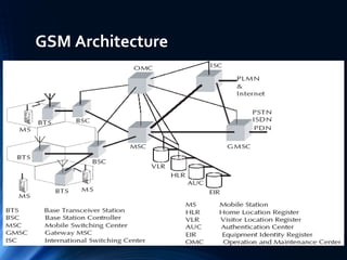
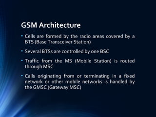
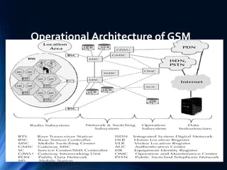
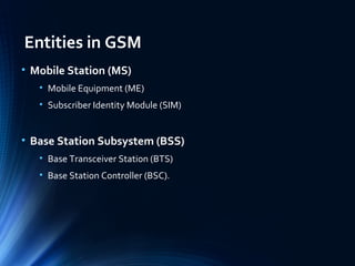
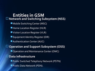
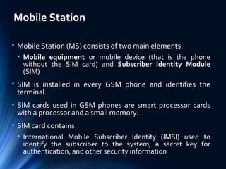
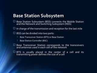
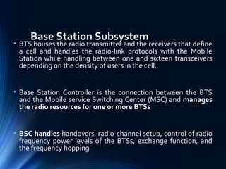
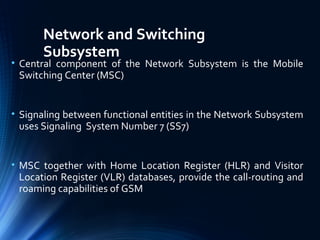
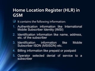
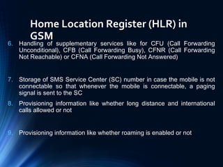
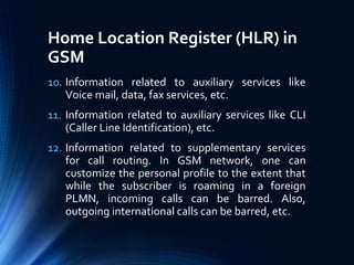
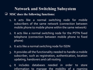
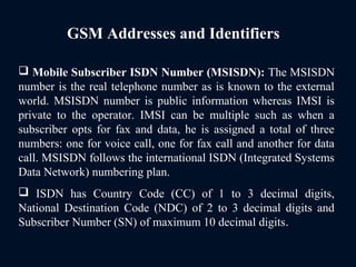
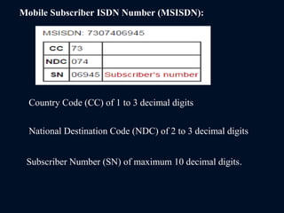
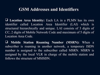
GSMGSM
(Global system for mobile communication)(Global system for mobile communication)
Jay Nagar(Cyber Security Researcher )Jay Nagar(Cyber Security Researcher )
+91-9601957620+91-9601957620
www.jaynagarblog.wordpress.comwww.jaynagarblog.wordpress.com
Outline
 Introduction
 GSM Architecture
 GSM Entities
 SMS Service In GSM
 Call Routing In GSM
 PLMN Interfaces
 GSM Addresses and Identifiers
 Network aspects in GSM
 Handover
 Mobility Management
 GSM Frequency Allocation
 Authentication and Security In GSM
www.jaynagarblog.wordpress.comwww.jaynagarblog.wordpress.com
Introduction
• GSM is second generation cellular standard
develop to voice service and data delivery using
digital modulation.
www.jaynagarblog.wordpress.comwww.jaynagarblog.wordpress.com
Goal Of GSM
• Improve Spectrum Efficiency
• International Roaming
• Low Cost mobile set and base station
• High quality speech
• Support for new service
• QOS
www.jaynagarblog.wordpress.comwww.jaynagarblog.wordpress.com
Use of TDMA and FDMA in GSM
• Uses a combination of FDMA (Frequency Division
Multiple Access) and TDMA (Time Division Multiple
Access)
• Allocation of 50 MHz (890–915 MHz and 935–960
MHz) bandwidth in the 900 MHz frequency band
and using FDMA further divided into 124 (125
channels, 1 not used) channels each with a carrier
bandwidth of 200 KHz
Use of TDMA and FDMA in GSM
• Using TDMA, each of the above mentioned
channels is then further divided into 8 time slots
• So, with the combination of FDMA and TDMA, a
maximum of 992 channels for transmit and receive
can be realized
Channel Allocation In GSM
• GSM used verity of channel which the data is
carried
• Channel are separate in two type
• Physical : Determine the time slot
• Logical
GSM System Hierarchy
• Consists at the minimum one administrative region
assigned to one MSC (Mobile Switching Centre)
• Administrative region is commonly known as
PLMN (Public Land Mobile Network)
• Each administrative region is subdivided into one
or many Location Area (LA)
• One LA consists of many cell groups and each cell
group is assigned to one BSC (Base Station
Controller)
GSM Architecture
GSM Architecture
• Cells are formed by the radio areas covered by a
BTS (Base Transceiver Station)
• Several BTSs are controlled by one BSC
• Traffic from the MS (Mobile Station) is routed
through MSC
• Calls originating from or terminating in a fixed
network or other mobile networks is handled by
the GMSC (Gateway MSC)
Operational Architecture of GSM
Entities in GSM
• Mobile Station (MS)
• Mobile Equipment (ME)
• Subscriber Identity Module (SIM)
• Base Station Subsystem (BSS)
• Base Transceiver Station (BTS)
• Base Station Controller (BSC).
Entities in GSM
 Network and Switching Subsystem (NSS)
Mobile Switching Center (MSC)
Home Location Register (HLR)
Visitor Location Register (VLR)
Equipment Identity Register (EIR)
Authentication Center (AUC)
 Operation and Support Subsystem (OSS)
Operation and Maintenance Center (OMC)
 Data infrastructure
Public Switched Telephony Network (PSTN)
Public Data Network (PDN).
Mobile Station
• Mobile Station (MS) consists of two main elements:
• Mobile equipment or mobile device (that is the phone
without the SIM card) and Subscriber Identity Module
(SIM)
• SIM is installed in every GSM phone and identifies the
terminal.
• SIM cards used in GSM phones are smart processor cards
with a processor and a small memory.
• SIM card contains
• International Mobile Subscriber Identity (IMSI) used to
identify the subscriber to the system, a secret key for
authentication, and other security information
Base Station Subsystem
 Base Station Subsystem (BSS) connects the Mobile Station
and the Network and Switching Subsystem (NSS)
 In charge of the transmission and reception for the last mile
 BSS can be divided into two parts:
 Base Transceiver Station (BTS) or Base Station
 Base Station Controller (BSC)
 Base Transceiver Station corresponds to the transceivers
and antennas used in each cell of the network
 BTS is usually placed in the center of a cell and its
transmitting power defines the size of a cell
Base Station Subsystem
• BTS houses the radio transmitter and the receivers that define
a cell and handles the radio-link protocols with the Mobile
Station while handling between one and sixteen transceivers
depending on the density of users in the cell.
• Base Station Controller is the connection between the BTS
and the Mobile service Switching Center (MSC) and manages
the radio resources for one or more BTSs
• BSC handles handovers, radio-channel setup, control of radio
frequency power levels of the BTSs, exchange function, and
the frequency hopping
Network and Switching
Subsystem
• Central component of the Network Subsystem is the Mobile
Switching Center (MSC)
• Signaling between functional entities in the Network Subsystem
uses Signaling System Number 7 (SS7)
• MSC together with Home Location Register (HLR) and Visitor
Location Register (VLR) databases, provide the call-routing and
roaming capabilities of GSM
Home Location Register (HLR) in
GSM
 It contains the following information:
1. Authentication information like International
Mobile Subscriber Identity (IMSI)
2. Identification information like name, address,
etc. of the subscriber
3. Identification information like Mobile
Subscriber ISDN (MSISDN) etc.
4. Billing information like prepaid or postpaid
5. Operator selected denial of service to a
subscriber
Home Location Register (HLR) in
GSM
6. Handling of supplementary services like for CFU (Call Forwarding
Unconditional), CFB (Call Forwarding Busy), CFNR (Call Forwarding
Not Reachable) or CFNA (Call Forwarding Not Answered)
7. Storage of SMS Service Center (SC) number in case the mobile is not
connectable so that whenever the mobile is connectable, a paging
signal is sent to the SC
8. Provisioning information like whether long distance and international
calls allowed or not
9. Provisioning information like whether roaming is enabled or not
Home Location Register (HLR) in
GSM
10. Information related to auxiliary services like
Voice mail, data, fax services, etc.
11. Information related to auxiliary services like CLI
(Caller Line Identification), etc.
12. Information related to supplementary services
for call routing. In GSM network, one can
customize the personal profile to the extent that
while the subscriber is roaming in a foreign
PLMN, incoming calls can be barred. Also,
outgoing international calls can be barred, etc.
Network and Switching Subsystem
 MSC does the following functions:
1. It acts like a normal switching node for mobile
subscribers of the same network (connection between
mobile phone to mobile phone within the same network)
2. It acts like a normal switching node for the PSTN fixed
telephone (connection between mobile phone to fixed
phone)
2. It acts like a normal switching node for ISDN
3. It provides all the functionality needed to handle a mobile
subscriber, such as registration, authentication, location
updating, handovers and call routing
4. It includes databases needed in order to store
information to manage the mobility of a roaming
Network Switching Subsystem
 MSC together with Home Location Register (HLR) and Visitor
Location Register (VLR) databases, provide the call-routing and
roaming capabilities of GSM
 HLR contains all the administrative information of each
subscriber registered in the corresponding GSM network
 Location of the mobile is typically in the form of the signaling
address of the VLR associated with the mobile station
 HLR is always fixed and stored in the home network, whereas
the VLR logically moves with the subscriber
 VLR is similar to a cache, whereas HLR is the persistent
storage
Network and Switching Subsystem
 VLR contains selected administrative information borrowed
from the HLR, necessary for call control and provisioning of the
subscribed services
 When a subscriber enters the covering area of a new MSC, the
VLR associated with this MSC can request information about the
new subscriber from its corresponding HLR in the home network
 There is a component called Gateway MSC (GMSC) that is
associated with the MSC
Network and Switching Subsystem
 GMSC is the interface between the mobile cellular
network and the PSTN and also is in charge of routing
calls from the fixed network towards a GSM user and
vice versa
 GMSC is often implemented in the same node as the
MSC
 GIWU (GSM Inter Working Unit) corresponds to an
interface to various networks for data communications
Operation and Support Subsystem
 Operations and Support Subsystem (OSS) controls and
monitors the GSM system
 OSS is connected to the different components of the NSS and
to the BSC and also in charge of controlling the traffic load of the
BSS
 Equipment Identity Register (EIR) rests with OSS
 EIR is a database that contains a list of all valid mobile
equipment within the network, where each mobile station is
identified by its International Mobile Equipment Identity (IMEI)
 EIR contains a list of IMEIs of all valid terminals
Operation and Support Subsystem
 An IMEI is marked as invalid if it has been reported
stolen or is not type approved
 The EIR allows the MSC to forbid calls from this
stolen or unauthorized terminals
 Authentication Center (AUC) is responsible for the
authentication of a subscriber
 AUC is a protected database and stores a copy of the
secret key stored in each subscriber’s SIM card
Short Message Service In GSM
 Short Message Service (SMS) is one of the most popular
services within GSM
 SMS is a data service and allows a user to enter text message
up to 160 characters in length when 7 bit English characters are
used
 SMS is a proactive bearer and is an ‘always on’ network
 Message center is referred to as Service Centre (SC) or SMS
Controller (SMSC)
 SMSC is a system within the core GSM network which works
as the store and forward system for SMS messages
SMS
 Two types of SMS:
SMMT (Short Message Mobile Terminated Point-to-Point)
SMMO (Short Message Mobile Originated Point-to-Point)
 SMMT is an incoming short message from the network and is
terminated in the MS (phone or Mobile Station)
 SMMO is an outgoing message originated in the MS, and
forwarded to the network for delivery
 For an outgoing message, the SMS is sent from the phone to
SC via the VLR and the Inter Working MSC (IWMSC)
 For incoming message, the path is from SC to the MS via the
HLR and the Gateway MSC (GMSC)
SMS Transfer
Call Routing In GSM
Call Routing In GSM
• Digitizer and source coding:
• The user speech is digitized at 8 KHz sampling rate using
Regular Pulse Excited–Linear Predictive Coder (RPE–LPC)
with a Long Term Predictor loop where information from
previous samples is used to predict the current sample.
Each sample is then represented in signed 13-bit linear
PCM value.
• This digitized data is passed to the coder with frames of
160 samples where encoder compresses these 160 samples
into 260-bits GSM frames resulting in one second of speech
compressed into 1625 bytes and achieving a rate of 13
Kbits/sec.
Call Routing In GSM
 Channel coding
 This introduces redundancy into the data for error
detection and possible error correction where the gross
bit rate after channel coding is 22.8 kbps (or 456 bits
every 20 ms). These 456 bits are divided into eight 57-
bit blocks and the result is interleaved amongst eight
successive time slot bursts for protection against burst
transmission errors.
 Interleaving
 This step rearranges a group of bits in a particular way to
improve the performance of the error-correction
mechanisms. The interleaving decreases the possibility of
losing whole bursts during the transmission by dispersing
the errors.
Call Routing In GSM Ciphering
 This encrypts blocks of user data using a symmetric key shared
by the mobile station and the BTS.
• Burst formatting
 It adds some binary information to the ciphered block for use in
synchronization and equalization of the received data.
• Modulation
 The modulation technique chosen for the GSM system is the
Gaussian Minimum Shift Keying (GMSK) where binary data is
converted back into analog signal to fit the frequency and time
requirements for the multiple access rules. This signal is then
radiated as radio wave over the air.
Call Routing In GSM
 Multipath and equalization
 An equalizer is in charge of extracting the ‘right’ signal from
the received signal while estimating the channel impulse
response of the GSM system and then it constructs an
inverse filter.
 The received signal is then passed through the inverse filter.
 Synchronization
 For successful operation of a mobile radio system, time and
frequency synchronization are needed. Frequency
synchronization is necessary so that the transmitter and
receiver frequency match (in FDMA) while Time
synchronization is necessary to identify the frame boundary
and the bits within the frame (in TDMA).
Call Routing
 The directory number dialed to reach a mobile subscriber is called the
Mobile Subscriber ISDN (MSISDN) which is defined by the E.164 numbering
plan and includes a country code and a National Destination Code, which
identifies the subscriber’s operator. The first few digits of the remaining
subscriber number may identify the subscriber’s HLR within the home PLMN
 For example, the MSISDN number of a subscriber in Bangalore associated
with Airtel network is +919845XYYYYY which is a unique number and
understood from anywhere in the world.+ means prefix for international
dialing, 91 is the country code for India and 45 is the network operator’s code
(Airtel in this case). X is the level number managed by the network operator
ranging from 0 to 9 while YYYYY is the subscriber code which is managed by
the operator.
Call Routing
Call Routing
 The call first goes to the local PSTN exchange where PSTN
exchange looks at the routing table and determines that it is a
call to a mobile network.
 PSTN forwards the call to the Gateway MSC (GMSC) of the
mobile network.
 MSC enquires the HLR to determine the status of the
subscriber. It will decide whether the call is to be routed or not. If
MSC finds that the call can be processed, it will find out the
address of the VLR where the mobile is expected to be present.
Call Routing
 If VLR is that of a different PLMN, it will forward the call
to the foreign PLMN through the Gateway MSC. If the VLR
is in the home network, it will determine the Location Area
(LA).
 Within the LA, it will page and locate the phone and
connect the call.
PLMN Interfaces
 Basic configuration of a GSM network contains a central
HLR and a central VLR where HLR contains all security,
provisioning and subscriber related information and VLR
stores the location information and other transient data.
 MSC needs subscriber parameter for successful call set-
up.
 Any data related to user call (connection, teardown etc.)
are processed with SS7 protocol for signaling using ISUP
(ISDN User Part) stack between network nodes.
 For mobile specific signaling, a protocol stack called MAP
(Mobile Application Part) is used over the SS7 network
which does all database transactions and handover/roaming
transactions between the MSC.
GSM Addresses and Identifiers
 International Mobile Station Equipment Identity (IMEI):
Every mobile equipment in this world has a unique identifier
which is called IMEI. IMEI is allocated by the equipment
manufacturer and registered by the network operator in the
Equipment Identity Register (EIR).
 International Mobile Subscriber Identity (IMSI): When
registered with a GSM operator, each subscriber is assigned a
unique identifier called IMSI which is stored in the SIM card and
secured by the operator. IMSI consists of several parts: 3 decimal
digits of Mobile Country Code (MCC), 2 decimal digits of
Mobile Network Code (MNC) and a maximum of 10 decimal
digits of Mobile Subscriber Identification Number (MSIN)
which is a unique number of the subscriber within the home
network.
3 decimal digits of Mobile
Country Code (MCC)
2 decimal digits of Mobile
Network Code (MNC)
A maximum of 10 decimal digits
of Mobile Subscriber
Identification Number (MSIN)
International Mobile Subscriber Identity (IMSI):
GSM Addresses and Identifiers
 Mobile Subscriber ISDN Number (MSISDN): The MSISDN
number is the real telephone number as is known to the external
world. MSISDN number is public information whereas IMSI is
private to the operator. IMSI can be multiple such as when a
subscriber opts for fax and data, he is assigned a total of three
numbers: one for voice call, one for fax call and another for data
call. MSISDN follows the international ISDN (Integrated Systems
Data Network) numbering plan.
 ISDN has Country Code (CC) of 1 to 3 decimal digits,
National Destination Code (NDC) of 2 to 3 decimal digits and
Subscriber Number (SN) of maximum 10 decimal digits.
Country Code (CC) of 1 to 3 decimal digits
National Destination Code (NDC) of 2 to 3 decimal digits
Subscriber Number (SN) of maximum 10 decimal digits.
Mobile Subscriber ISDN Number (MSISDN):
GSM Addresses and Identifiers
 Location Area Identity: Each LA in a PLMN has its own
identifier called Location Area Identifier (LAI) which is
structured hierarchically and unique. LAI consists of 3 digits of
CC, 2 digits of Mobile Network Code and maximum of 5 digits of
Location Area Code.
 Mobile Station Roaming Number (MSRN): When a
subscriber is roaming in another network, a temporary ISDN
number is assigned to the subscriber called MSRN. MSRN is
assigned by the local VLR in charge of the mobile station and
follows the structure of MSISDN.
GSM Addresses and Identifiers
 Temporary Mobile Subscriber Identity (TMSI): TMSI is a
temporary identifier assigned by the serving VLR used in place of
the IMSI for identification and addressing of the mobile station.
Together with the current location area, a TMSI allows a
subscriber to be identified uniquely.
 Local Mobile Subscriber Identity (LMSI): LMSI is assigned
by the VLR and stored in the HLR and is used as a searching key
for faster database access within the VLR.
 Cell Identifier: Within a LA, every cell has a unique Cell
Identifier (CI) and together with a LAI, a cell can be identified
uniquely through Global Cell Identity (LAI & CI).
 MSCs and Location Registers (HLR & VLR) are addressed
with ISDN numbers while they may use a Signaling Point Code
(SPC) within a PLMN.
Network aspects in GSM
Signaling protocol structure in GSM
Network aspects in GSM
 Layer 1 is the physical layer which uses the channel structures
over the air interface.
 Layer 2 is the data link layer and across the Um interface, the
data link layer is a modified version of the LAPD protocol used in
ISDN or X.25, called LAPDm.
 Across the A interface, the Message Transfer Part layer 2 of
Signaling System Number 7 is used.
Network aspects in GSM
 Layer 3 of the GSM signaling protocol is itself divided
into three sub-layers:
1. Radio Resources Management: It controls the set-up,
maintenance and termination of radio and fixed channels,
including handovers.
2. Mobility Management: It manages the location updating and
registration procedures as well as security and authentication.
3. Connection Management: It handles general call control and
manages Supplementary Services and the Short Message
Service.
Handover
 The procedure of change of resources is called handover when
the user is mobile while the call is in progress.
 There are four different types of handover in the GSM system,
which involve transferring a call between:
1. Channels (time slots) in the same cell
2. Cells (Base Transceiver Stations) under the control of the
same Base Station Controller (BSC)
3. Cells under the control of different BSCs but belonging to the
same Mobile Switching Center (MSC)
4. Cells under the control of different MSCs
Handover
 First two types of handover, called internal handovers, involve
only one Base Station Controller (BSC). To save signaling
bandwidth, they are managed by the BSC without involving the
Mobile services Switching Center (MSC), except to notify it at
the completion of the handover.
 Last two types of handover, called external handovers, are
handled by the MSC.
Mobility Management
 Mobility Management (MM) function handles the procedures
that arise from the mobility of the subscriber and is in charge of
all the aspects related to the mobility of the user, especially the
roaming, the location management, and the
security/authentication of the subscriber.
 First location update procedure is called the IMSI attach
procedure where the MS indicates its IMSI to the network
whereas when a mobile station is powered off, it performs an
IMSI detach procedure in order to tell the network that it is no
longer connected.
Mobility Management
 A location update message is sent to the new MSC/VLR which
records the location area information and then sends the location
information to the subscriber’s HLR.
 If the mobile station is authenticated and authorized in the new
MSC/VLR, the subscriber’s HLR cancels the registration of the
mobile station with the old MSC/VLR.
 Location update is also performed periodically and if after the
updating time period, the mobile station has not registered, it is
then deregistered.
Mobility Management
 When there is an incoming call for a subscriber, the mobile
phone needs to be located and a channel needs to be allocated and
the call connected.
 A powered-on mobile is informed of an incoming call by a
paging message sent over the paging channel of the cells within
the current location area while location updating procedures and
subsequent call routing use MSC, HLR and VLR.
 If the subscriber is entitled to service, HLR sends a subset of
the subscriber information needed for call control to the new
MSC/VLR and sends a message to the old MSC/VLR to cancel
the old registration.
Mobility Management
 An incoming mobile terminating call is directed to the
Gateway MSC (GMSC) function which, as a switch, interrogates
the subscriber’s HLR to obtain routing information and thus
contains a table linking MSISDNs to their corresponding HLRs.
 The routing information that is returned to the GMSC is the
Mobile Station Roaming Number (MSRN).
 MSRNs are related to the geographical numbering plan and not
visible to subscribers.
Mobility Management
 Generally, GMSC queries the called subscriber’s HLR for an
MSRN.
 HLR stores only the SS7 address of the subscriber’s current
VLR while VLR temporarily allocates an MSRN from its pool for
the call.
 MSRN is returned to the HLR and back to the GMSC, which
can then route the call to the new MSC. At new MSC, IMSI
corresponding to the MSRN is looked up and the mobile station is
paged in its current location area.
 HLR is referred for incoming call whereas VLR is referred for
outgoing call.
GSM Frequency Allocation
 Normally, GSM uses 900 MHz band wherein 890-915 MHz is
allocated for the uplink (mobile station to base station) and 935–
960 MHz is allocated for the downlink (base station to mobile
station). Each way the bandwidth for the GSM system is 25 MHz
which provides 125 carriers uplink/downlink each having a
bandwidth of 200 kHz.
 ARFCN (Absolute Radio Frequency Channel Numbers) denote
a forward and reverse channel pair which is separated in
frequency by 45 MHz.
 Practically, a guard band of 100 kHz is provided at the upper
and lower end of the GSM 900 MHz spectrum and only 124
(duplex) channels are implemented.
GSM Frequency Allocation
 GSM uses a combination of Time Division Multiple Access
(TDMA) and Frequency Division Multiple Access (FDMA)
encoding.
 One or more carrier frequencies are assigned to each base
station and each of these carrier frequencies is then divided in
time using a TDMA scheme where fundamental unit is called a
burst period lasting approximately 0.577 ms.
 Eight burst periods are grouped into a TDMA frame of
approximately 4.615 ms which forms the basic unit for the
definition of logical channels.
 One physical channel is one burst period per TDMA frame
while, normally, channels are defined by the number and position
of their corresponding burst periods.
GSM Frequency Allocation
Carrier frequencies and TDMA frames
Authentication and Security
 Authentication involves two functional entities - the SIM card
in the mobile phone and the Authentication Center (AUC).
 Following authentication by algorithm A3, a key is generated
for encryption.
 An algorithm A8 is used to generate the key while a different
algorithm called A5 is used for both ciphering and deciphering
procedures for signaling, voice and data.
 So, SS7 signal, voice, data, and SMS within GSM networks are
ciphered over the wireless radio interface.
A3 Algorithm
 During authentication, MSC challenges the MS with a random
number (RAND).
 SIM card uses this RAND received from the MSC and a secret
key Kj stored within the SIM as input. Both the RAND and the Kj
secret are 128 bits long. Using the A3 algorithm with RAND and
Kj as input a 32-bit output called signature response (SRES) is
generated in the MS and then sent back to MSC.
 Using the same set of algorithms, the AUC also generates a
SRES. The SRES from MS and the SRES generated by the AUC
are compared.
 If they are the same, the MS is authenticated.
A3 Algorithm
 The idea is that no keys will be transacted over the air.
However, if the SRES values calculated independently by the
SIM and the AUC are the same, then Kj has to be same and if Kj
is same, SIM card is genuine.
A8 Algorithm
 A8 algorithm is the key generation algorithm.
 A8 generates a session key, Kc, from the random challenge
RAND (received from the MSC) and from the secret key Kj.
 Keys are generated at both the MS and the network end. The
session key, Kc, is used for ciphering till the MSC decides to
authenticate the MS once again.
A5 Algorithm
 A5 is the stream cipher algorithm used to encrypt over-the-air
transmissions. The stream cipher is initialized all over again for
every frame sent with the session key, Kc, and the number of the
frame being encrypted or decrypted.
 Same Kc is used throughout the call but the 22-bit frame
number changes during the call, thus, generating a unique key
stream for every frame.

Global system for mobile communication(GSM)

  • 1.
    GSMGSM (Global system formobile communication)(Global system for mobile communication) Jay Nagar(Cyber Security Researcher )Jay Nagar(Cyber Security Researcher ) +91-9601957620+91-9601957620 www.jaynagarblog.wordpress.comwww.jaynagarblog.wordpress.com
  • 2.
    Outline  Introduction  GSMArchitecture  GSM Entities  SMS Service In GSM  Call Routing In GSM  PLMN Interfaces  GSM Addresses and Identifiers  Network aspects in GSM  Handover  Mobility Management  GSM Frequency Allocation  Authentication and Security In GSM www.jaynagarblog.wordpress.comwww.jaynagarblog.wordpress.com
  • 3.
    Introduction • GSM issecond generation cellular standard develop to voice service and data delivery using digital modulation. www.jaynagarblog.wordpress.comwww.jaynagarblog.wordpress.com
  • 4.
    Goal Of GSM •Improve Spectrum Efficiency • International Roaming • Low Cost mobile set and base station • High quality speech • Support for new service • QOS www.jaynagarblog.wordpress.comwww.jaynagarblog.wordpress.com
  • 5.
    Use of TDMAand FDMA in GSM • Uses a combination of FDMA (Frequency Division Multiple Access) and TDMA (Time Division Multiple Access) • Allocation of 50 MHz (890–915 MHz and 935–960 MHz) bandwidth in the 900 MHz frequency band and using FDMA further divided into 124 (125 channels, 1 not used) channels each with a carrier bandwidth of 200 KHz
  • 6.
    Use of TDMAand FDMA in GSM • Using TDMA, each of the above mentioned channels is then further divided into 8 time slots • So, with the combination of FDMA and TDMA, a maximum of 992 channels for transmit and receive can be realized
  • 7.
    Channel Allocation InGSM • GSM used verity of channel which the data is carried • Channel are separate in two type • Physical : Determine the time slot • Logical
  • 8.
  • 9.
    GSM System Hierarchy •Consists at the minimum one administrative region assigned to one MSC (Mobile Switching Centre) • Administrative region is commonly known as PLMN (Public Land Mobile Network) • Each administrative region is subdivided into one or many Location Area (LA) • One LA consists of many cell groups and each cell group is assigned to one BSC (Base Station Controller)
  • 10.
  • 11.
    GSM Architecture • Cellsare formed by the radio areas covered by a BTS (Base Transceiver Station) • Several BTSs are controlled by one BSC • Traffic from the MS (Mobile Station) is routed through MSC • Calls originating from or terminating in a fixed network or other mobile networks is handled by the GMSC (Gateway MSC)
  • 12.
  • 13.
    Entities in GSM •Mobile Station (MS) • Mobile Equipment (ME) • Subscriber Identity Module (SIM) • Base Station Subsystem (BSS) • Base Transceiver Station (BTS) • Base Station Controller (BSC).
  • 14.
    Entities in GSM Network and Switching Subsystem (NSS) Mobile Switching Center (MSC) Home Location Register (HLR) Visitor Location Register (VLR) Equipment Identity Register (EIR) Authentication Center (AUC)  Operation and Support Subsystem (OSS) Operation and Maintenance Center (OMC)  Data infrastructure Public Switched Telephony Network (PSTN) Public Data Network (PDN).
  • 15.
    Mobile Station • MobileStation (MS) consists of two main elements: • Mobile equipment or mobile device (that is the phone without the SIM card) and Subscriber Identity Module (SIM) • SIM is installed in every GSM phone and identifies the terminal. • SIM cards used in GSM phones are smart processor cards with a processor and a small memory. • SIM card contains • International Mobile Subscriber Identity (IMSI) used to identify the subscriber to the system, a secret key for authentication, and other security information
  • 16.
    Base Station Subsystem Base Station Subsystem (BSS) connects the Mobile Station and the Network and Switching Subsystem (NSS)  In charge of the transmission and reception for the last mile  BSS can be divided into two parts:  Base Transceiver Station (BTS) or Base Station  Base Station Controller (BSC)  Base Transceiver Station corresponds to the transceivers and antennas used in each cell of the network  BTS is usually placed in the center of a cell and its transmitting power defines the size of a cell
  • 17.
    Base Station Subsystem •BTS houses the radio transmitter and the receivers that define a cell and handles the radio-link protocols with the Mobile Station while handling between one and sixteen transceivers depending on the density of users in the cell. • Base Station Controller is the connection between the BTS and the Mobile service Switching Center (MSC) and manages the radio resources for one or more BTSs • BSC handles handovers, radio-channel setup, control of radio frequency power levels of the BTSs, exchange function, and the frequency hopping
  • 18.
    Network and Switching Subsystem •Central component of the Network Subsystem is the Mobile Switching Center (MSC) • Signaling between functional entities in the Network Subsystem uses Signaling System Number 7 (SS7) • MSC together with Home Location Register (HLR) and Visitor Location Register (VLR) databases, provide the call-routing and roaming capabilities of GSM
  • 19.
    Home Location Register(HLR) in GSM  It contains the following information: 1. Authentication information like International Mobile Subscriber Identity (IMSI) 2. Identification information like name, address, etc. of the subscriber 3. Identification information like Mobile Subscriber ISDN (MSISDN) etc. 4. Billing information like prepaid or postpaid 5. Operator selected denial of service to a subscriber
  • 20.
    Home Location Register(HLR) in GSM 6. Handling of supplementary services like for CFU (Call Forwarding Unconditional), CFB (Call Forwarding Busy), CFNR (Call Forwarding Not Reachable) or CFNA (Call Forwarding Not Answered) 7. Storage of SMS Service Center (SC) number in case the mobile is not connectable so that whenever the mobile is connectable, a paging signal is sent to the SC 8. Provisioning information like whether long distance and international calls allowed or not 9. Provisioning information like whether roaming is enabled or not
  • 21.
    Home Location Register(HLR) in GSM 10. Information related to auxiliary services like Voice mail, data, fax services, etc. 11. Information related to auxiliary services like CLI (Caller Line Identification), etc. 12. Information related to supplementary services for call routing. In GSM network, one can customize the personal profile to the extent that while the subscriber is roaming in a foreign PLMN, incoming calls can be barred. Also, outgoing international calls can be barred, etc.
  • 22.
    Network and SwitchingSubsystem  MSC does the following functions: 1. It acts like a normal switching node for mobile subscribers of the same network (connection between mobile phone to mobile phone within the same network) 2. It acts like a normal switching node for the PSTN fixed telephone (connection between mobile phone to fixed phone) 2. It acts like a normal switching node for ISDN 3. It provides all the functionality needed to handle a mobile subscriber, such as registration, authentication, location updating, handovers and call routing 4. It includes databases needed in order to store information to manage the mobility of a roaming
  • 23.
    Network Switching Subsystem MSC together with Home Location Register (HLR) and Visitor Location Register (VLR) databases, provide the call-routing and roaming capabilities of GSM  HLR contains all the administrative information of each subscriber registered in the corresponding GSM network  Location of the mobile is typically in the form of the signaling address of the VLR associated with the mobile station  HLR is always fixed and stored in the home network, whereas the VLR logically moves with the subscriber  VLR is similar to a cache, whereas HLR is the persistent storage
  • 24.
    Network and SwitchingSubsystem  VLR contains selected administrative information borrowed from the HLR, necessary for call control and provisioning of the subscribed services  When a subscriber enters the covering area of a new MSC, the VLR associated with this MSC can request information about the new subscriber from its corresponding HLR in the home network  There is a component called Gateway MSC (GMSC) that is associated with the MSC
  • 25.
    Network and SwitchingSubsystem  GMSC is the interface between the mobile cellular network and the PSTN and also is in charge of routing calls from the fixed network towards a GSM user and vice versa  GMSC is often implemented in the same node as the MSC  GIWU (GSM Inter Working Unit) corresponds to an interface to various networks for data communications
  • 26.
    Operation and SupportSubsystem  Operations and Support Subsystem (OSS) controls and monitors the GSM system  OSS is connected to the different components of the NSS and to the BSC and also in charge of controlling the traffic load of the BSS  Equipment Identity Register (EIR) rests with OSS  EIR is a database that contains a list of all valid mobile equipment within the network, where each mobile station is identified by its International Mobile Equipment Identity (IMEI)  EIR contains a list of IMEIs of all valid terminals
  • 27.
    Operation and SupportSubsystem  An IMEI is marked as invalid if it has been reported stolen or is not type approved  The EIR allows the MSC to forbid calls from this stolen or unauthorized terminals  Authentication Center (AUC) is responsible for the authentication of a subscriber  AUC is a protected database and stores a copy of the secret key stored in each subscriber’s SIM card
  • 30.
    Short Message ServiceIn GSM  Short Message Service (SMS) is one of the most popular services within GSM  SMS is a data service and allows a user to enter text message up to 160 characters in length when 7 bit English characters are used  SMS is a proactive bearer and is an ‘always on’ network  Message center is referred to as Service Centre (SC) or SMS Controller (SMSC)  SMSC is a system within the core GSM network which works as the store and forward system for SMS messages
  • 31.
    SMS  Two typesof SMS: SMMT (Short Message Mobile Terminated Point-to-Point) SMMO (Short Message Mobile Originated Point-to-Point)  SMMT is an incoming short message from the network and is terminated in the MS (phone or Mobile Station)  SMMO is an outgoing message originated in the MS, and forwarded to the network for delivery  For an outgoing message, the SMS is sent from the phone to SC via the VLR and the Inter Working MSC (IWMSC)  For incoming message, the path is from SC to the MS via the HLR and the Gateway MSC (GMSC)
  • 32.
  • 33.
  • 34.
    Call Routing InGSM • Digitizer and source coding: • The user speech is digitized at 8 KHz sampling rate using Regular Pulse Excited–Linear Predictive Coder (RPE–LPC) with a Long Term Predictor loop where information from previous samples is used to predict the current sample. Each sample is then represented in signed 13-bit linear PCM value. • This digitized data is passed to the coder with frames of 160 samples where encoder compresses these 160 samples into 260-bits GSM frames resulting in one second of speech compressed into 1625 bytes and achieving a rate of 13 Kbits/sec.
  • 35.
    Call Routing InGSM  Channel coding  This introduces redundancy into the data for error detection and possible error correction where the gross bit rate after channel coding is 22.8 kbps (or 456 bits every 20 ms). These 456 bits are divided into eight 57- bit blocks and the result is interleaved amongst eight successive time slot bursts for protection against burst transmission errors.  Interleaving  This step rearranges a group of bits in a particular way to improve the performance of the error-correction mechanisms. The interleaving decreases the possibility of losing whole bursts during the transmission by dispersing the errors.
  • 36.
    Call Routing InGSM Ciphering  This encrypts blocks of user data using a symmetric key shared by the mobile station and the BTS. • Burst formatting  It adds some binary information to the ciphered block for use in synchronization and equalization of the received data. • Modulation  The modulation technique chosen for the GSM system is the Gaussian Minimum Shift Keying (GMSK) where binary data is converted back into analog signal to fit the frequency and time requirements for the multiple access rules. This signal is then radiated as radio wave over the air.
  • 37.
    Call Routing InGSM  Multipath and equalization  An equalizer is in charge of extracting the ‘right’ signal from the received signal while estimating the channel impulse response of the GSM system and then it constructs an inverse filter.  The received signal is then passed through the inverse filter.  Synchronization  For successful operation of a mobile radio system, time and frequency synchronization are needed. Frequency synchronization is necessary so that the transmitter and receiver frequency match (in FDMA) while Time synchronization is necessary to identify the frame boundary and the bits within the frame (in TDMA).
  • 38.
    Call Routing  Thedirectory number dialed to reach a mobile subscriber is called the Mobile Subscriber ISDN (MSISDN) which is defined by the E.164 numbering plan and includes a country code and a National Destination Code, which identifies the subscriber’s operator. The first few digits of the remaining subscriber number may identify the subscriber’s HLR within the home PLMN  For example, the MSISDN number of a subscriber in Bangalore associated with Airtel network is +919845XYYYYY which is a unique number and understood from anywhere in the world.+ means prefix for international dialing, 91 is the country code for India and 45 is the network operator’s code (Airtel in this case). X is the level number managed by the network operator ranging from 0 to 9 while YYYYY is the subscriber code which is managed by the operator.
  • 39.
  • 40.
    Call Routing  Thecall first goes to the local PSTN exchange where PSTN exchange looks at the routing table and determines that it is a call to a mobile network.  PSTN forwards the call to the Gateway MSC (GMSC) of the mobile network.  MSC enquires the HLR to determine the status of the subscriber. It will decide whether the call is to be routed or not. If MSC finds that the call can be processed, it will find out the address of the VLR where the mobile is expected to be present.
  • 41.
    Call Routing  IfVLR is that of a different PLMN, it will forward the call to the foreign PLMN through the Gateway MSC. If the VLR is in the home network, it will determine the Location Area (LA).  Within the LA, it will page and locate the phone and connect the call.
  • 42.
    PLMN Interfaces  Basicconfiguration of a GSM network contains a central HLR and a central VLR where HLR contains all security, provisioning and subscriber related information and VLR stores the location information and other transient data.  MSC needs subscriber parameter for successful call set- up.  Any data related to user call (connection, teardown etc.) are processed with SS7 protocol for signaling using ISUP (ISDN User Part) stack between network nodes.  For mobile specific signaling, a protocol stack called MAP (Mobile Application Part) is used over the SS7 network which does all database transactions and handover/roaming transactions between the MSC.
  • 43.
    GSM Addresses andIdentifiers  International Mobile Station Equipment Identity (IMEI): Every mobile equipment in this world has a unique identifier which is called IMEI. IMEI is allocated by the equipment manufacturer and registered by the network operator in the Equipment Identity Register (EIR).  International Mobile Subscriber Identity (IMSI): When registered with a GSM operator, each subscriber is assigned a unique identifier called IMSI which is stored in the SIM card and secured by the operator. IMSI consists of several parts: 3 decimal digits of Mobile Country Code (MCC), 2 decimal digits of Mobile Network Code (MNC) and a maximum of 10 decimal digits of Mobile Subscriber Identification Number (MSIN) which is a unique number of the subscriber within the home network.
  • 44.
    3 decimal digitsof Mobile Country Code (MCC) 2 decimal digits of Mobile Network Code (MNC) A maximum of 10 decimal digits of Mobile Subscriber Identification Number (MSIN) International Mobile Subscriber Identity (IMSI):
  • 46.
    GSM Addresses andIdentifiers  Mobile Subscriber ISDN Number (MSISDN): The MSISDN number is the real telephone number as is known to the external world. MSISDN number is public information whereas IMSI is private to the operator. IMSI can be multiple such as when a subscriber opts for fax and data, he is assigned a total of three numbers: one for voice call, one for fax call and another for data call. MSISDN follows the international ISDN (Integrated Systems Data Network) numbering plan.  ISDN has Country Code (CC) of 1 to 3 decimal digits, National Destination Code (NDC) of 2 to 3 decimal digits and Subscriber Number (SN) of maximum 10 decimal digits.
  • 47.
    Country Code (CC)of 1 to 3 decimal digits National Destination Code (NDC) of 2 to 3 decimal digits Subscriber Number (SN) of maximum 10 decimal digits. Mobile Subscriber ISDN Number (MSISDN):
  • 48.
    GSM Addresses andIdentifiers  Location Area Identity: Each LA in a PLMN has its own identifier called Location Area Identifier (LAI) which is structured hierarchically and unique. LAI consists of 3 digits of CC, 2 digits of Mobile Network Code and maximum of 5 digits of Location Area Code.  Mobile Station Roaming Number (MSRN): When a subscriber is roaming in another network, a temporary ISDN number is assigned to the subscriber called MSRN. MSRN is assigned by the local VLR in charge of the mobile station and follows the structure of MSISDN.
  • 49.
    GSM Addresses andIdentifiers  Temporary Mobile Subscriber Identity (TMSI): TMSI is a temporary identifier assigned by the serving VLR used in place of the IMSI for identification and addressing of the mobile station. Together with the current location area, a TMSI allows a subscriber to be identified uniquely.  Local Mobile Subscriber Identity (LMSI): LMSI is assigned by the VLR and stored in the HLR and is used as a searching key for faster database access within the VLR.  Cell Identifier: Within a LA, every cell has a unique Cell Identifier (CI) and together with a LAI, a cell can be identified uniquely through Global Cell Identity (LAI & CI).  MSCs and Location Registers (HLR & VLR) are addressed with ISDN numbers while they may use a Signaling Point Code (SPC) within a PLMN.
  • 50.
    Network aspects inGSM Signaling protocol structure in GSM
  • 51.
    Network aspects inGSM  Layer 1 is the physical layer which uses the channel structures over the air interface.  Layer 2 is the data link layer and across the Um interface, the data link layer is a modified version of the LAPD protocol used in ISDN or X.25, called LAPDm.  Across the A interface, the Message Transfer Part layer 2 of Signaling System Number 7 is used.
  • 52.
    Network aspects inGSM  Layer 3 of the GSM signaling protocol is itself divided into three sub-layers: 1. Radio Resources Management: It controls the set-up, maintenance and termination of radio and fixed channels, including handovers. 2. Mobility Management: It manages the location updating and registration procedures as well as security and authentication. 3. Connection Management: It handles general call control and manages Supplementary Services and the Short Message Service.
  • 53.
    Handover  The procedureof change of resources is called handover when the user is mobile while the call is in progress.  There are four different types of handover in the GSM system, which involve transferring a call between: 1. Channels (time slots) in the same cell 2. Cells (Base Transceiver Stations) under the control of the same Base Station Controller (BSC) 3. Cells under the control of different BSCs but belonging to the same Mobile Switching Center (MSC) 4. Cells under the control of different MSCs
  • 54.
    Handover  First twotypes of handover, called internal handovers, involve only one Base Station Controller (BSC). To save signaling bandwidth, they are managed by the BSC without involving the Mobile services Switching Center (MSC), except to notify it at the completion of the handover.  Last two types of handover, called external handovers, are handled by the MSC.
  • 55.
    Mobility Management  MobilityManagement (MM) function handles the procedures that arise from the mobility of the subscriber and is in charge of all the aspects related to the mobility of the user, especially the roaming, the location management, and the security/authentication of the subscriber.  First location update procedure is called the IMSI attach procedure where the MS indicates its IMSI to the network whereas when a mobile station is powered off, it performs an IMSI detach procedure in order to tell the network that it is no longer connected.
  • 56.
    Mobility Management  Alocation update message is sent to the new MSC/VLR which records the location area information and then sends the location information to the subscriber’s HLR.  If the mobile station is authenticated and authorized in the new MSC/VLR, the subscriber’s HLR cancels the registration of the mobile station with the old MSC/VLR.  Location update is also performed periodically and if after the updating time period, the mobile station has not registered, it is then deregistered.
  • 57.
    Mobility Management  Whenthere is an incoming call for a subscriber, the mobile phone needs to be located and a channel needs to be allocated and the call connected.  A powered-on mobile is informed of an incoming call by a paging message sent over the paging channel of the cells within the current location area while location updating procedures and subsequent call routing use MSC, HLR and VLR.  If the subscriber is entitled to service, HLR sends a subset of the subscriber information needed for call control to the new MSC/VLR and sends a message to the old MSC/VLR to cancel the old registration.
  • 58.
    Mobility Management  Anincoming mobile terminating call is directed to the Gateway MSC (GMSC) function which, as a switch, interrogates the subscriber’s HLR to obtain routing information and thus contains a table linking MSISDNs to their corresponding HLRs.  The routing information that is returned to the GMSC is the Mobile Station Roaming Number (MSRN).  MSRNs are related to the geographical numbering plan and not visible to subscribers.
  • 59.
    Mobility Management  Generally,GMSC queries the called subscriber’s HLR for an MSRN.  HLR stores only the SS7 address of the subscriber’s current VLR while VLR temporarily allocates an MSRN from its pool for the call.  MSRN is returned to the HLR and back to the GMSC, which can then route the call to the new MSC. At new MSC, IMSI corresponding to the MSRN is looked up and the mobile station is paged in its current location area.  HLR is referred for incoming call whereas VLR is referred for outgoing call.
  • 60.
    GSM Frequency Allocation Normally, GSM uses 900 MHz band wherein 890-915 MHz is allocated for the uplink (mobile station to base station) and 935– 960 MHz is allocated for the downlink (base station to mobile station). Each way the bandwidth for the GSM system is 25 MHz which provides 125 carriers uplink/downlink each having a bandwidth of 200 kHz.  ARFCN (Absolute Radio Frequency Channel Numbers) denote a forward and reverse channel pair which is separated in frequency by 45 MHz.  Practically, a guard band of 100 kHz is provided at the upper and lower end of the GSM 900 MHz spectrum and only 124 (duplex) channels are implemented.
  • 61.
    GSM Frequency Allocation GSM uses a combination of Time Division Multiple Access (TDMA) and Frequency Division Multiple Access (FDMA) encoding.  One or more carrier frequencies are assigned to each base station and each of these carrier frequencies is then divided in time using a TDMA scheme where fundamental unit is called a burst period lasting approximately 0.577 ms.  Eight burst periods are grouped into a TDMA frame of approximately 4.615 ms which forms the basic unit for the definition of logical channels.  One physical channel is one burst period per TDMA frame while, normally, channels are defined by the number and position of their corresponding burst periods.
  • 62.
    GSM Frequency Allocation Carrierfrequencies and TDMA frames
  • 63.
    Authentication and Security Authentication involves two functional entities - the SIM card in the mobile phone and the Authentication Center (AUC).  Following authentication by algorithm A3, a key is generated for encryption.  An algorithm A8 is used to generate the key while a different algorithm called A5 is used for both ciphering and deciphering procedures for signaling, voice and data.  So, SS7 signal, voice, data, and SMS within GSM networks are ciphered over the wireless radio interface.
  • 64.
    A3 Algorithm  Duringauthentication, MSC challenges the MS with a random number (RAND).  SIM card uses this RAND received from the MSC and a secret key Kj stored within the SIM as input. Both the RAND and the Kj secret are 128 bits long. Using the A3 algorithm with RAND and Kj as input a 32-bit output called signature response (SRES) is generated in the MS and then sent back to MSC.  Using the same set of algorithms, the AUC also generates a SRES. The SRES from MS and the SRES generated by the AUC are compared.  If they are the same, the MS is authenticated.
  • 65.
    A3 Algorithm  Theidea is that no keys will be transacted over the air. However, if the SRES values calculated independently by the SIM and the AUC are the same, then Kj has to be same and if Kj is same, SIM card is genuine.
  • 66.
    A8 Algorithm  A8algorithm is the key generation algorithm.  A8 generates a session key, Kc, from the random challenge RAND (received from the MSC) and from the secret key Kj.  Keys are generated at both the MS and the network end. The session key, Kc, is used for ciphering till the MSC decides to authenticate the MS once again.
  • 67.
    A5 Algorithm  A5is the stream cipher algorithm used to encrypt over-the-air transmissions. The stream cipher is initialized all over again for every frame sent with the session key, Kc, and the number of the frame being encrypted or decrypted.  Same Kc is used throughout the call but the 22-bit frame number changes during the call, thus, generating a unique key stream for every frame.