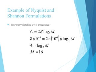
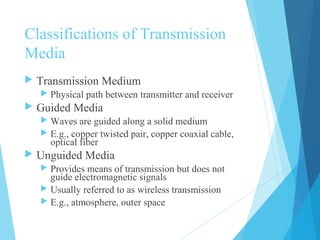
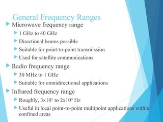
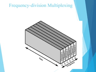
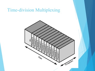
Transmission
Fundamentals
Chapter 2
Electromagnetic Signal
 Function of time
 Can also be expressed as a function of
frequency
 Signal consists of components of different frequencies
 The frequency domain of a signal is far more
important that time domain both are discussed
here
Time-Domain Concepts
 Analog signal - signal intensity varies in a
smooth fashion over time
 No breaks or discontinuities in the signal
 Digital signal - signal intensity maintains a
constant level for some period of time and then
changes to another constant level
 Periodic signal - analog or digital signal
pattern that repeats over time
 s(t +T ) = s(t ) -¥ < t < + ¥
 where T is the period of the signal
Time-Domain Concepts
 Aperiodic signal - analog or digital signal
pattern that doesn't repeat over time
 Peak amplitude (A) - maximum value or
strength of the signal over time; typically
measured in volts
 Frequency (f )
 Rate, in cycles per second, or Hertz (Hz) at which
the signal repeats
Time-Domain Concepts
 Period (T ) - amount of time it takes for one
repetition of the signal
 T = 1/f
 Phase (φ) - measure of the relative position in
time within a single period of a signal
 Wavelength (λ) - distance occupied by a
single cycle of the signal
 Or, the distance between two points of
corresponding phase of two consecutive cycles
Sine Wave Parameters
 General sine wave
 s(t ) = A sin(2πft + φ)
 Figure 2.3 shows the effect of varying each of
the three parameters
 (a) A = 1, f = 1 Hz, φ = 0; thus T = 1s
 (b) Reduced peak amplitude; A=0.5
 (c) Increased frequency; f = 2, thus T = ½
 (d) Phase shift; φ = π/4 radians (45 degrees)
 note: 2π radians = 360° = 1 period
Sine Wave Parameters
Frequency-Domain Concepts
 Fundamental frequency - when all frequency
components of a signal are integer multiples of
one frequency, it’s referred to as the
fundamental frequency
 Spectrum - range of frequencies that a signal
contains
 Absolute bandwidth - width of the spectrum of
a signal
 Effective bandwidth (or just bandwidth) -
narrow band of frequencies that most of the
signal’s energy is contained in
Frequency-Domain Concepts
 Any electromagnetic signal can be shown to
consist of a collection of periodic analog signals
(sine waves) at different amplitudes, frequencies,
and phases
 The period of the total signal is equal to the
period of the fundamental frequency
Relationship between Data Rate
and Bandwidth
 The greater the bandwidth, the higher the
information-carrying capacity
 Conclusions
 Any digital waveform will have infinite
bandwidth
 BUT the transmission system will limit the
bandwidth that can be transmitted
 AND, for any given medium, the greater the
bandwidth transmitted, the greater the cost
 HOWEVER, limiting the bandwidth creates
distortions
Data Communication Terms
 Data - entities that convey meaning, or
information
 Signals - electric or electromagnetic
representations of data
 Transmission - communication of data by the
propagation and processing of signals
Examples of Analog and Digital
Data
 Analog
 Video
 Audio
 Digital
 Text
 Integers
Analog Signals
 A continuously varying electromagnetic wave
that may be propagated over a variety of media,
depending on frequency
 Examples of media:
 Copper wire media (twisted pair and coaxial cable)
 Fiber optic cable
 Atmosphere or space propagation
 Analog signals can propagate analog and digital
data
Digital Signals
 A sequence of voltage pulses that may be transmitted
over a copper wire medium
 Generally cheaper than analog signaling
 Less susceptible to noise interference
 Suffer more from attenuation
 Digital signals can propagate analog and digital data
Analog Signaling
Digital Signaling
Reasons for Choosing Data and
Signal Combinations
 Digital data, digital signal
 Equipment for encoding is less expensive than digital-to-
analog equipment
 Analog data, digital signal
 Conversion permits use of modern digital transmission and
switching equipment
 Digital data, analog signal
 Some transmission media will only propagate analog signals
 Examples include optical fiber and satellite
 Analog data, analog signal
 Analog data easily converted to analog signal
Analog Transmission
 Transmit analog signals without regard
to content
 Attenuation limits length of
transmission link
 Cascaded amplifiers boost signal’s
energy for longer distances but cause
distortion
 Analog data can tolerate distortion
 Introduces errors in digital data
Digital Transmission
 Concerned with the content of the signal
 Attenuation endangers integrity of data
 Digital Signal
 Repeaters achieve greater distance
 Repeaters recover the signal and retransmit
 Analog signal carrying digital data
 Retransmission device recovers the digital
data from analog signal
 Generates new, clean analog signal
About Channel Capacity
 Impairments, such as noise, limit data rate that
can be achieved
 For digital data, to what extent do impairments
limit data rate?
 Channel Capacity – the maximum rate at which
data can be transmitted over a given
communication path, or channel, under given
conditions
Concepts Related to Channel
Capacity
 Data rate - rate at which data can be
communicated (bps)
 Bandwidth - the bandwidth of the
transmitted signal as constrained by the
transmitter and the nature of the
transmission medium (Hertz)
 Noise - average level of noise over the
communications path
 Error rate - rate at which errors occur
 Error = transmit 1 and receive 0; transmit 0 and
receive 1
Nyquist Bandwidth
 For binary signals (two voltage levels)
 C = 2B
 With multilevel signaling
 C = 2B log2
M
 M = number of discrete signal or voltage levels
Signal-to-Noise Ratio
 Ratio of the power in a signal to the power
contained in the noise that’s present at a
particular point in the transmission
 Typically measured at a receiver
 Signal-to-noise ratio (SNR, or S/N)
 A high SNR means a high-quality signal, low
number of required intermediate repeaters
 SNR sets upper bound on achievable data rate
powernoise
powersignal
log10)( 10dB =SNR
Shannon Capacity Formula
 Equation:
 Represents theoretical maximum that can
be achieved
 In practice, only much lower rates achieved
 Formula assumes white noise (thermal noise)
 Impulse noise is not accounted for
 Attenuation distortion or delay distortion not
accounted for
( )SNR1log2 += BC
Example of Nyquist and
Shannon Formulations
 Spectrum of a channel between 3 MHz and 4 MHz ; SNRdB
=
24 dB
 Using Shannon’s formula
( )
251SNR
SNRlog10dB24SNR
MHz1MHz3MHz4
10dB
=
==
=−=B
( ) Mbps88102511log10 6
2
6
=×≈+×=C
Example of Nyquist and
Shannon Formulations
 How many signaling levels are required?
( )
16
log4
log102108
log2
2
2
66
2
=
=
××=×
=
M
M
M
MBC
Classifications of Transmission
Media
 Transmission Medium
 Physical path between transmitter and receiver
 Guided Media
 Waves are guided along a solid medium
 E.g., copper twisted pair, copper coaxial cable,
optical fiber
 Unguided Media
 Provides means of transmission but does not
guide electromagnetic signals
 Usually referred to as wireless transmission
 E.g., atmosphere, outer space
Unguided Media
 Transmission and reception are achieved
by means of an antenna
 Configurations for wireless transmission
 Directional
 Omnidirectional
General Frequency Ranges
 Microwave frequency range
 1 GHz to 40 GHz
 Directional beams possible
 Suitable for point-to-point transmission
 Used for satellite communications
 Radio frequency range
 30 MHz to 1 GHz
 Suitable for omnidirectional applications
 Infrared frequency range
 Roughly, 3x10¹¹
to 2x10¹⁴
Hz
 Useful in local point-to-point multipoint applications within
confined areas
Terrestrial Microwave
 Description of common microwave antenna
 Parabolic "dish", 3 m in diameter
 Fixed rigidly and focuses a narrow beam to achieves
line-of-sight transmission to receiving antenna
 Located at substantial heights above ground level
 Applications
 Long haul telecommunications service
 Short point-to-point links between buildings
Satellite Microwave
 Description of communication satellite
 It is also Microwave relay station
 Used to link two or more ground-based microwave
transmitter/receivers
 Receives transmissions on one frequency band
(uplink), amplifies or repeats the signal, and transmits
it on another frequency (downlink)
 Applications
 Television distribution
 Long-distance telephone transmission
 Private business networks
Broadcast Radio
 Description of broadcast radio antennas
 Omnidirectional
 Antennas not required to be dish-shaped
 Antennas need not be rigidly mounted to a precise
alignment
 Applications
 Broadcast radio
 VHF and part of the UHF band; 30 MHZ to 1GHz
 Covers FM radio and UHF and VHF television
Infrared
 Achieved by transceivers (transmitters/
receivers)
 Transmission must be within the line of sight
of each other
Multiplexing
 Capacity of transmission medium usually
exceeds capacity required for transmission of a
single signal
 Multiplexing - carrying multiple signals on a
single medium
 More efficient use of transmission medium
Multiplexing
Reasons for Widespread Use of
Multiplexing
 Cost per kbps of transmission facility declines
with an increase in the data rate
 Cost of transmission and receiving equipment
declines with increased data rate
 Most individual data communicating devices
require relatively modest data rate support
Multiplexing Techniques
 Frequency-division multiplexing (FDM)
 Takes advantage of the fact that the useful
bandwidth of the medium exceeds the
required bandwidth of a given signal
 Time-division multiplexing (TDM)
 Takes advantage of the fact that the
achievable bit rate of the medium exceeds
the required data rate of a digital signal
Frequency-division Multiplexing
Time-division Multiplexing

Chapter#2

  • 1.
  • 2.
    Electromagnetic Signal  Functionof time  Can also be expressed as a function of frequency  Signal consists of components of different frequencies  The frequency domain of a signal is far more important that time domain both are discussed here
  • 3.
    Time-Domain Concepts  Analogsignal - signal intensity varies in a smooth fashion over time  No breaks or discontinuities in the signal  Digital signal - signal intensity maintains a constant level for some period of time and then changes to another constant level  Periodic signal - analog or digital signal pattern that repeats over time  s(t +T ) = s(t ) -¥ < t < + ¥  where T is the period of the signal
  • 4.
    Time-Domain Concepts  Aperiodicsignal - analog or digital signal pattern that doesn't repeat over time  Peak amplitude (A) - maximum value or strength of the signal over time; typically measured in volts  Frequency (f )  Rate, in cycles per second, or Hertz (Hz) at which the signal repeats
  • 5.
    Time-Domain Concepts  Period(T ) - amount of time it takes for one repetition of the signal  T = 1/f  Phase (φ) - measure of the relative position in time within a single period of a signal  Wavelength (λ) - distance occupied by a single cycle of the signal  Or, the distance between two points of corresponding phase of two consecutive cycles
  • 6.
    Sine Wave Parameters General sine wave  s(t ) = A sin(2πft + φ)  Figure 2.3 shows the effect of varying each of the three parameters  (a) A = 1, f = 1 Hz, φ = 0; thus T = 1s  (b) Reduced peak amplitude; A=0.5  (c) Increased frequency; f = 2, thus T = ½  (d) Phase shift; φ = π/4 radians (45 degrees)  note: 2π radians = 360° = 1 period
  • 7.
  • 8.
    Frequency-Domain Concepts  Fundamentalfrequency - when all frequency components of a signal are integer multiples of one frequency, it’s referred to as the fundamental frequency  Spectrum - range of frequencies that a signal contains  Absolute bandwidth - width of the spectrum of a signal  Effective bandwidth (or just bandwidth) - narrow band of frequencies that most of the signal’s energy is contained in
  • 9.
    Frequency-Domain Concepts  Anyelectromagnetic signal can be shown to consist of a collection of periodic analog signals (sine waves) at different amplitudes, frequencies, and phases  The period of the total signal is equal to the period of the fundamental frequency
  • 10.
    Relationship between DataRate and Bandwidth  The greater the bandwidth, the higher the information-carrying capacity  Conclusions  Any digital waveform will have infinite bandwidth  BUT the transmission system will limit the bandwidth that can be transmitted  AND, for any given medium, the greater the bandwidth transmitted, the greater the cost  HOWEVER, limiting the bandwidth creates distortions
  • 11.
    Data Communication Terms Data - entities that convey meaning, or information  Signals - electric or electromagnetic representations of data  Transmission - communication of data by the propagation and processing of signals
  • 12.
    Examples of Analogand Digital Data  Analog  Video  Audio  Digital  Text  Integers
  • 13.
    Analog Signals  Acontinuously varying electromagnetic wave that may be propagated over a variety of media, depending on frequency  Examples of media:  Copper wire media (twisted pair and coaxial cable)  Fiber optic cable  Atmosphere or space propagation  Analog signals can propagate analog and digital data
  • 14.
    Digital Signals  Asequence of voltage pulses that may be transmitted over a copper wire medium  Generally cheaper than analog signaling  Less susceptible to noise interference  Suffer more from attenuation  Digital signals can propagate analog and digital data
  • 15.
  • 16.
  • 17.
    Reasons for ChoosingData and Signal Combinations  Digital data, digital signal  Equipment for encoding is less expensive than digital-to- analog equipment  Analog data, digital signal  Conversion permits use of modern digital transmission and switching equipment  Digital data, analog signal  Some transmission media will only propagate analog signals  Examples include optical fiber and satellite  Analog data, analog signal  Analog data easily converted to analog signal
  • 18.
    Analog Transmission  Transmitanalog signals without regard to content  Attenuation limits length of transmission link  Cascaded amplifiers boost signal’s energy for longer distances but cause distortion  Analog data can tolerate distortion  Introduces errors in digital data
  • 19.
    Digital Transmission  Concernedwith the content of the signal  Attenuation endangers integrity of data  Digital Signal  Repeaters achieve greater distance  Repeaters recover the signal and retransmit  Analog signal carrying digital data  Retransmission device recovers the digital data from analog signal  Generates new, clean analog signal
  • 20.
    About Channel Capacity Impairments, such as noise, limit data rate that can be achieved  For digital data, to what extent do impairments limit data rate?  Channel Capacity – the maximum rate at which data can be transmitted over a given communication path, or channel, under given conditions
  • 21.
    Concepts Related toChannel Capacity  Data rate - rate at which data can be communicated (bps)  Bandwidth - the bandwidth of the transmitted signal as constrained by the transmitter and the nature of the transmission medium (Hertz)  Noise - average level of noise over the communications path  Error rate - rate at which errors occur  Error = transmit 1 and receive 0; transmit 0 and receive 1
  • 22.
    Nyquist Bandwidth  Forbinary signals (two voltage levels)  C = 2B  With multilevel signaling  C = 2B log2 M  M = number of discrete signal or voltage levels
  • 23.
    Signal-to-Noise Ratio  Ratioof the power in a signal to the power contained in the noise that’s present at a particular point in the transmission  Typically measured at a receiver  Signal-to-noise ratio (SNR, or S/N)  A high SNR means a high-quality signal, low number of required intermediate repeaters  SNR sets upper bound on achievable data rate powernoise powersignal log10)( 10dB =SNR
  • 24.
    Shannon Capacity Formula Equation:  Represents theoretical maximum that can be achieved  In practice, only much lower rates achieved  Formula assumes white noise (thermal noise)  Impulse noise is not accounted for  Attenuation distortion or delay distortion not accounted for ( )SNR1log2 += BC
  • 25.
    Example of Nyquistand Shannon Formulations  Spectrum of a channel between 3 MHz and 4 MHz ; SNRdB = 24 dB  Using Shannon’s formula ( ) 251SNR SNRlog10dB24SNR MHz1MHz3MHz4 10dB = == =−=B ( ) Mbps88102511log10 6 2 6 =×≈+×=C
  • 26.
    Example of Nyquistand Shannon Formulations  How many signaling levels are required? ( ) 16 log4 log102108 log2 2 2 66 2 = = ××=× = M M M MBC
  • 27.
    Classifications of Transmission Media Transmission Medium  Physical path between transmitter and receiver  Guided Media  Waves are guided along a solid medium  E.g., copper twisted pair, copper coaxial cable, optical fiber  Unguided Media  Provides means of transmission but does not guide electromagnetic signals  Usually referred to as wireless transmission  E.g., atmosphere, outer space
  • 28.
    Unguided Media  Transmissionand reception are achieved by means of an antenna  Configurations for wireless transmission  Directional  Omnidirectional
  • 29.
    General Frequency Ranges Microwave frequency range  1 GHz to 40 GHz  Directional beams possible  Suitable for point-to-point transmission  Used for satellite communications  Radio frequency range  30 MHz to 1 GHz  Suitable for omnidirectional applications  Infrared frequency range  Roughly, 3x10¹¹ to 2x10¹⁴ Hz  Useful in local point-to-point multipoint applications within confined areas
  • 30.
    Terrestrial Microwave  Descriptionof common microwave antenna  Parabolic "dish", 3 m in diameter  Fixed rigidly and focuses a narrow beam to achieves line-of-sight transmission to receiving antenna  Located at substantial heights above ground level  Applications  Long haul telecommunications service  Short point-to-point links between buildings
  • 31.
    Satellite Microwave  Descriptionof communication satellite  It is also Microwave relay station  Used to link two or more ground-based microwave transmitter/receivers  Receives transmissions on one frequency band (uplink), amplifies or repeats the signal, and transmits it on another frequency (downlink)  Applications  Television distribution  Long-distance telephone transmission  Private business networks
  • 32.
    Broadcast Radio  Descriptionof broadcast radio antennas  Omnidirectional  Antennas not required to be dish-shaped  Antennas need not be rigidly mounted to a precise alignment  Applications  Broadcast radio  VHF and part of the UHF band; 30 MHZ to 1GHz  Covers FM radio and UHF and VHF television
  • 33.
    Infrared  Achieved bytransceivers (transmitters/ receivers)  Transmission must be within the line of sight of each other
  • 34.
    Multiplexing  Capacity oftransmission medium usually exceeds capacity required for transmission of a single signal  Multiplexing - carrying multiple signals on a single medium  More efficient use of transmission medium
  • 35.
  • 36.
    Reasons for WidespreadUse of Multiplexing  Cost per kbps of transmission facility declines with an increase in the data rate  Cost of transmission and receiving equipment declines with increased data rate  Most individual data communicating devices require relatively modest data rate support
  • 37.
    Multiplexing Techniques  Frequency-divisionmultiplexing (FDM)  Takes advantage of the fact that the useful bandwidth of the medium exceeds the required bandwidth of a given signal  Time-division multiplexing (TDM)  Takes advantage of the fact that the achievable bit rate of the medium exceeds the required data rate of a digital signal
  • 38.
  • 39.

Editor's Notes

  • #16 Codec: A device or program that compresses data to enable faster transmission and decompresses received data.