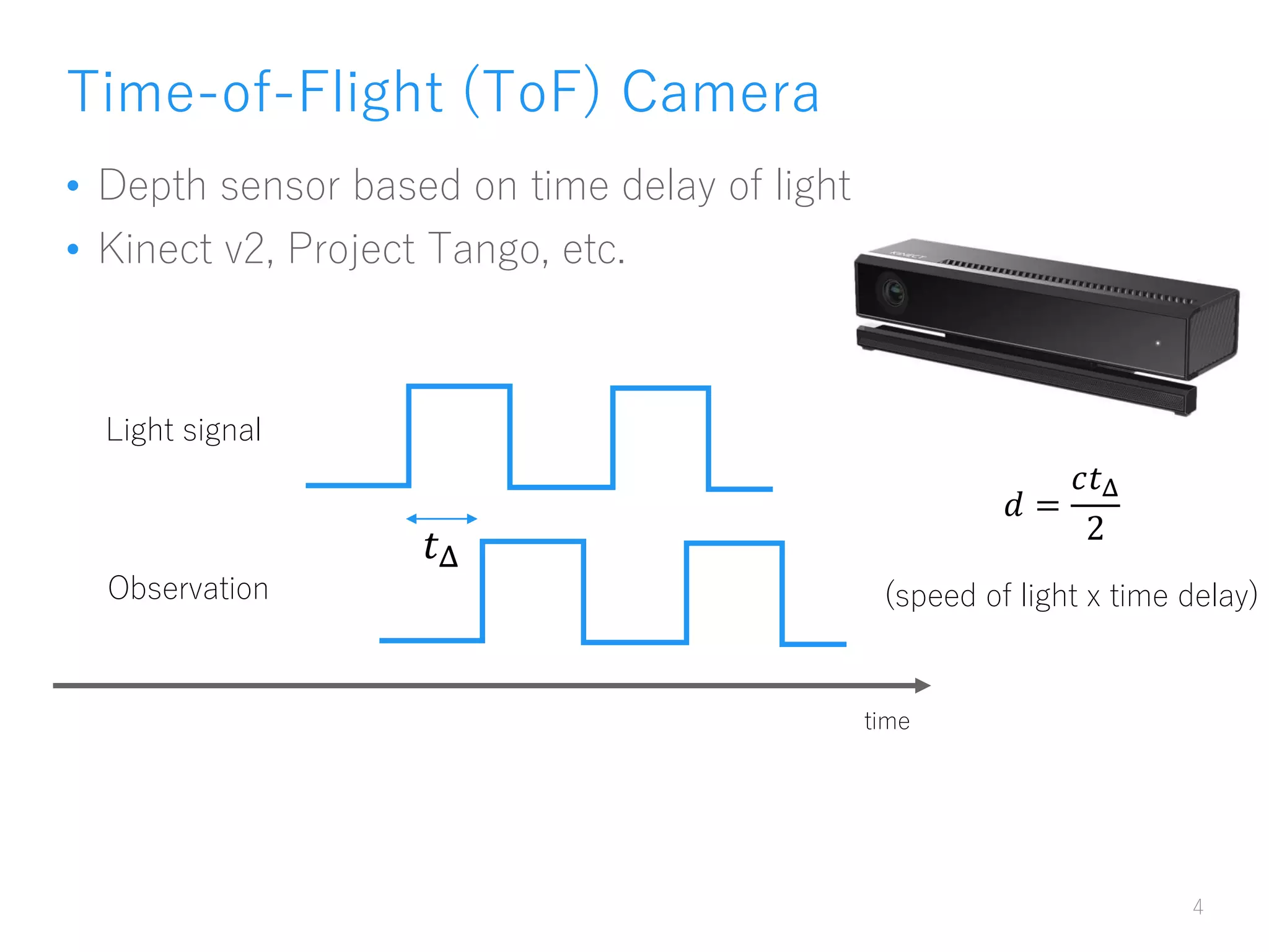
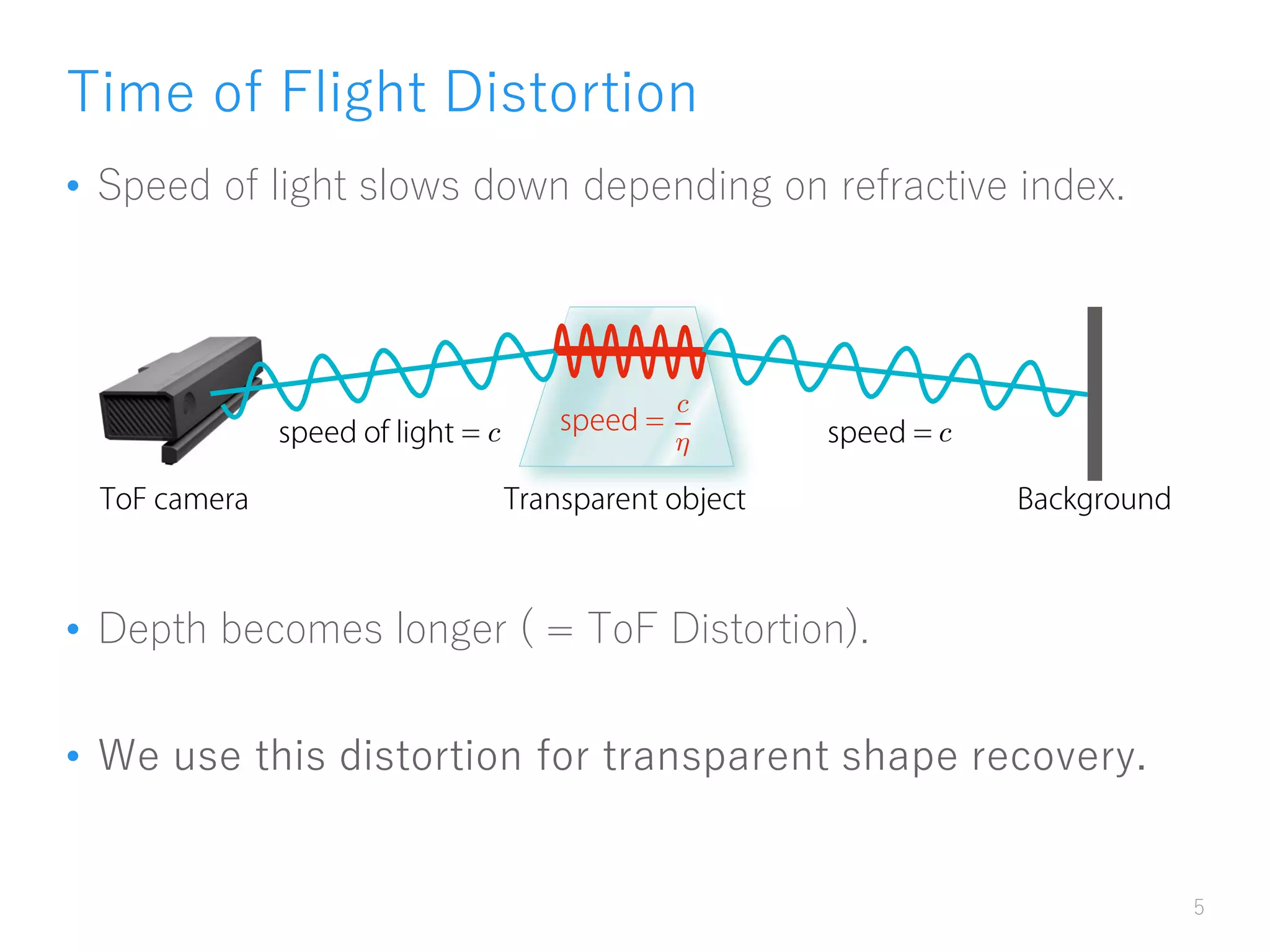
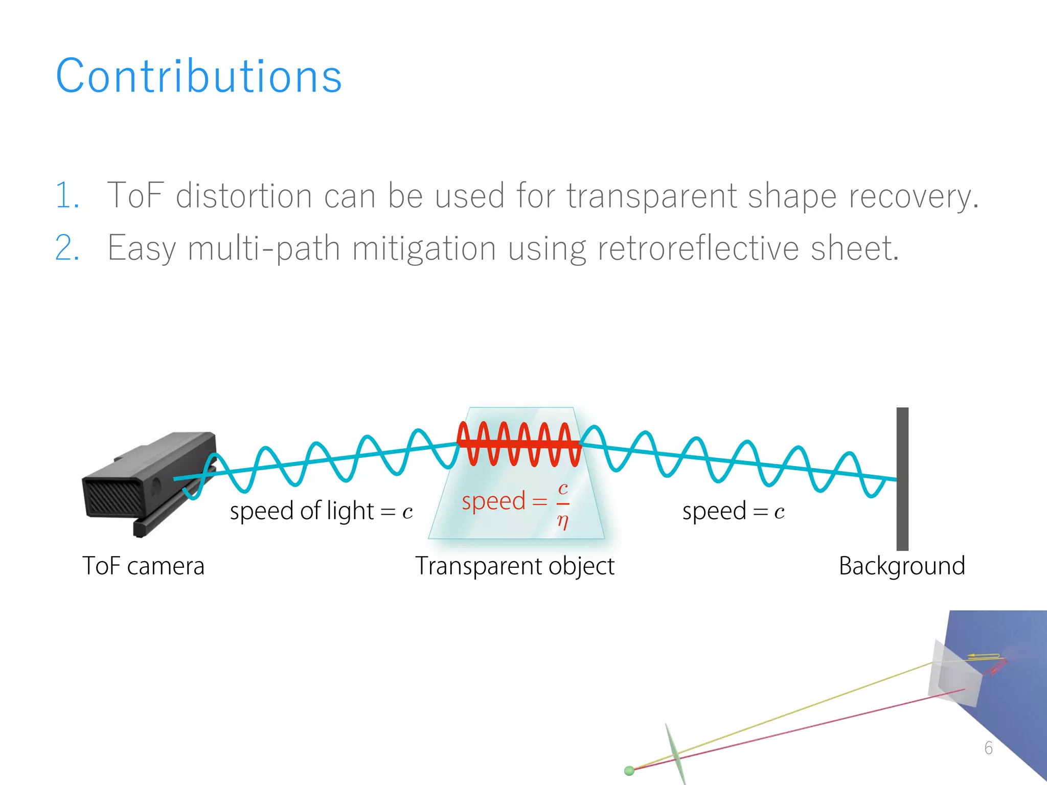
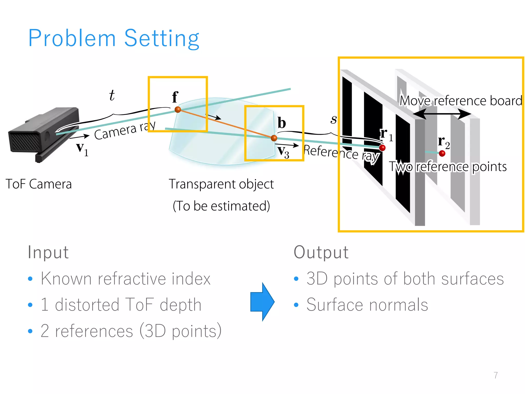
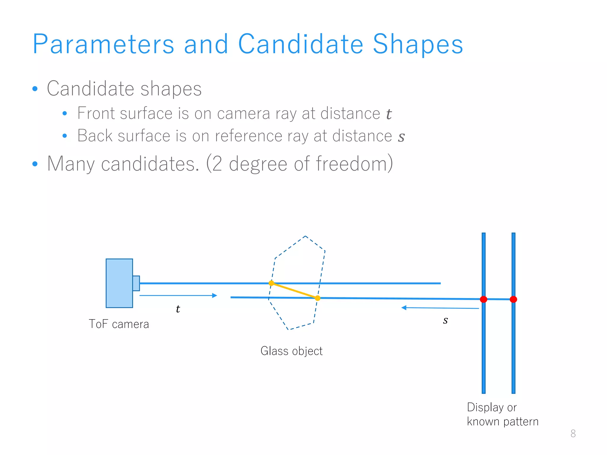
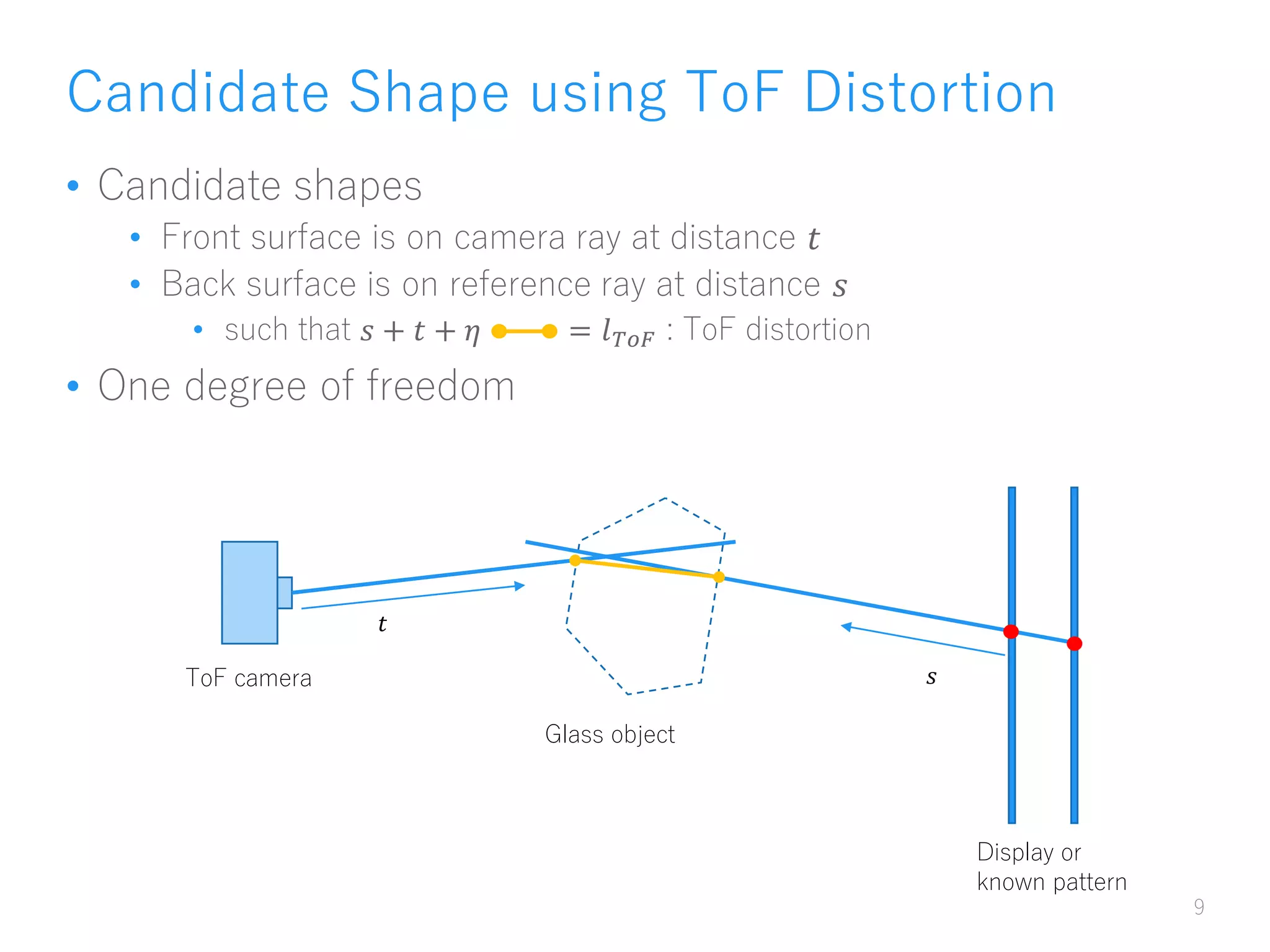
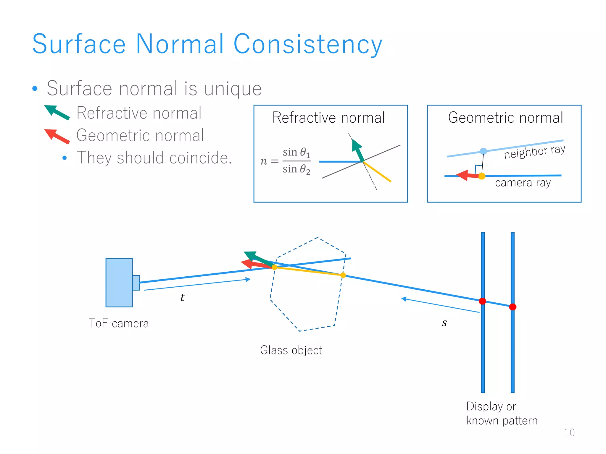
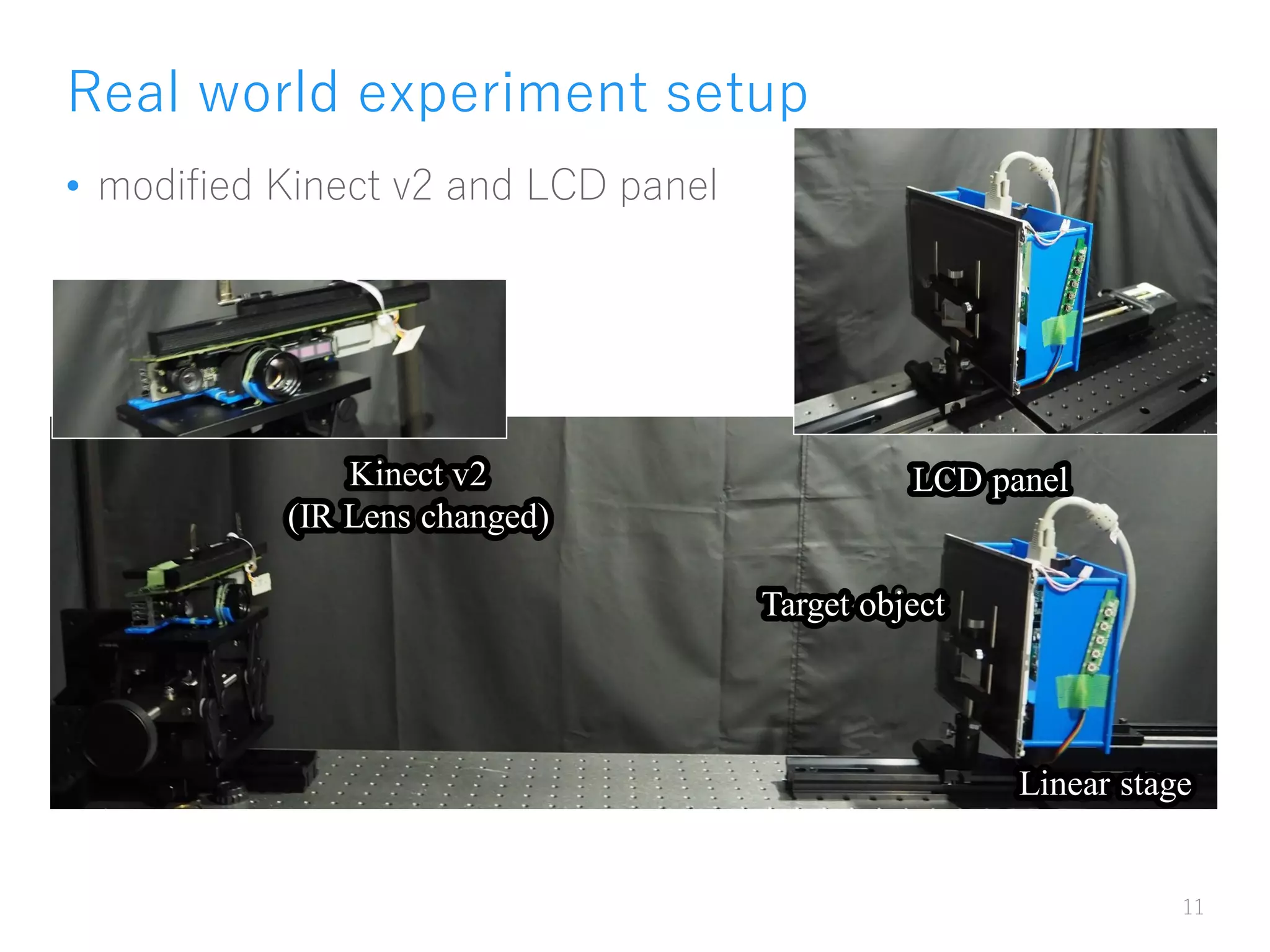
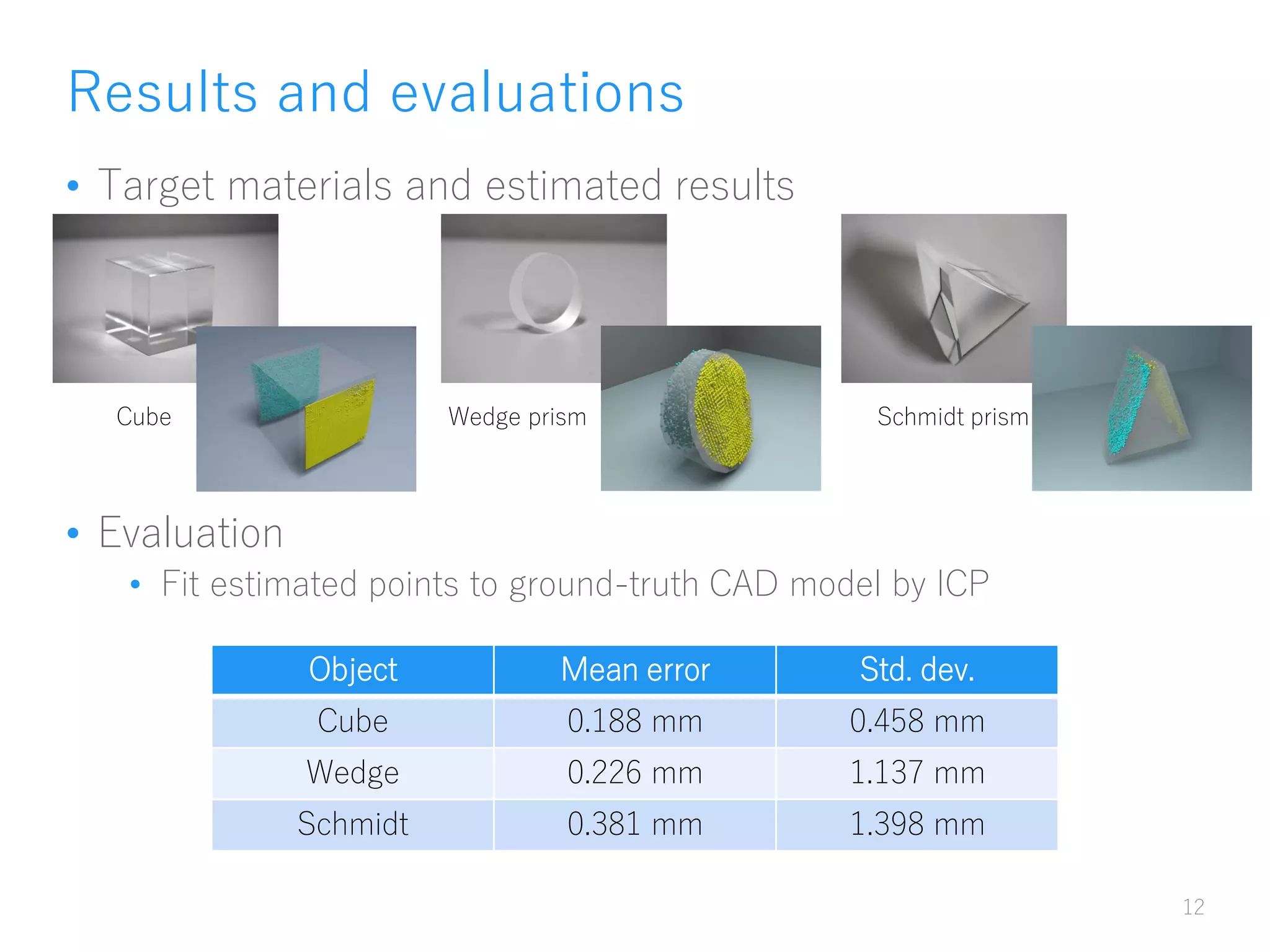
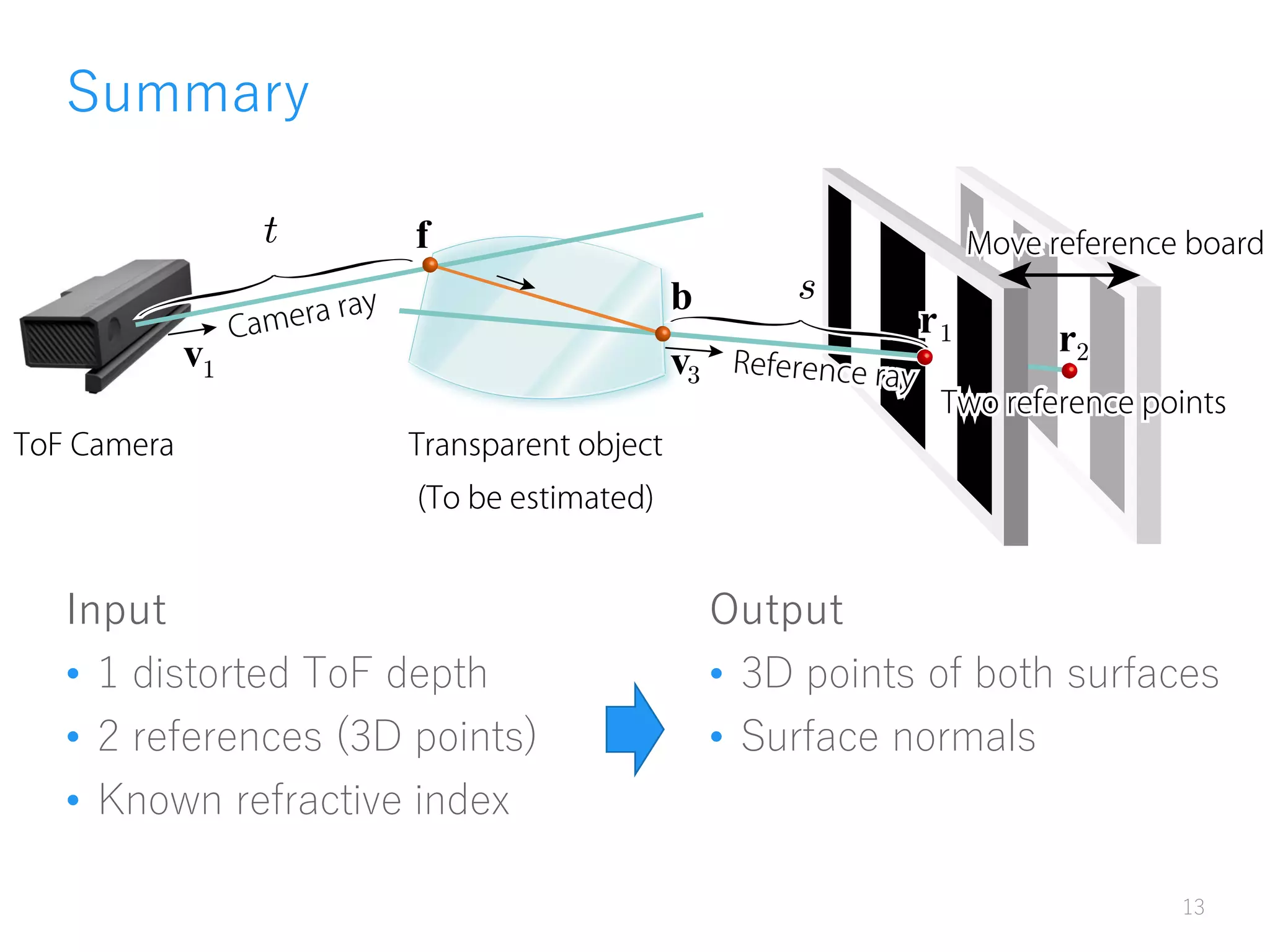
Recovering Transparent Shape
from Time-of-Flight Distortion
(CVPR2016)
1
K. Tanaka Y. Mukaigawa H. Kubo Y. Matsushita Y. Yagi
Transparent Objects
• Invisible, but distorted background can be seen.
• 3D reconstruction of transparent material is challenging.
3
Sensor
Estimated point
by triangulation
BackgroundReference
Distorted
Time-of-Flight (ToF) Camera
• Depth sensor based on time delay of light
• Kinect v2, Project Tango, etc.
4
time
Light signal
Observation
𝑡Δ
𝑑 =
𝑐𝑡Δ
2
(speed of light x time delay)
Time of Flight Distortion
• Speed of light slows down depending on refractive index.
• Depth becomes longer ( = ToF Distortion).
• We use this distortion for transparent shape recovery.
5
c
c
c
Contributions
6
1. ToF distortion can be used for transparent shape recovery.
2. Easy multi-path mitigation using retroreflective sheet.
c
c
c
Problem Setting
Input
• Known refractive index
• 1 distorted ToF depth
• 2 references (3D points)
7
r
f
b
r
t
v v
r
s
Output
• 3D points of both surfaces
• Surface normals
Parameters and Candidate Shapes
• Candidate shapes
• Front surface is on camera ray at distance 𝑡
• Back surface is on reference ray at distance 𝑠
• Many candidates. (2 degree of freedom)
8
ToF camera
𝑡
Glass object
Display or
known pattern
𝑠
Candidate Shape using ToF Distortion
• Candidate shapes
• Front surface is on camera ray at distance 𝑡
• Back surface is on reference ray at distance 𝑠
• such that 𝑠 + 𝑡 + 𝜂 = 𝑙 𝑇𝑜𝐹 : ToF distortion
• One degree of freedom
9
ToF camera
𝑡
Glass object
Display or
known pattern
𝑠
Surface Normal Consistency
• Surface normal is unique
Refractive normal
Geometric normal
• They should coincide.
10
ToF camera
𝑡
Glass object
Display or
known pattern
𝑠
𝑛 =
sin 𝜃1
sin 𝜃2
Refractive normal
camera ray
Geometric normal
Real world experiment setup
• modified Kinect v2 and LCD panel
11
Kinect v2
(IR Lens changed)
LCD panel
Linear stage
Target object
Results and evaluations
• Target materials and estimated results
• Evaluation
• Fit estimated points to ground-truth CAD model by ICP
12
Cube Wedge prism Schmidt prism
Object Mean error Std. dev.
Cube 0.188 mm 0.458 mm
Wedge 0.226 mm 1.137 mm
Schmidt 0.381 mm 1.398 mm
Summary
Input
• 1 distorted ToF depth
• 2 references (3D points)
• Known refractive index
13
r
f
b
r
t
v v
r
s
Output
• 3D points of both surfaces
• Surface normals
Time-of-Flight as alternative imager
• Light-in-flight [Gkioulekas+2015]
• Parameter tunable ToF camera (Texas instruments)
14
Imaging, Analyzing using ToF Camera
• Recently Emerging Topic
[Heide+2013], [Kadambi+2013], [Naik+2013], [Godbaz+2013], [Freedman+2014],
[Lin+2014], [O’Toole+2014], [Gupta+2015], [Heide+2015], [Xiao+2015],
[Kadambi+2015], [Peters+2015], [Tadano+2015], and more!
• CVPR 2016
• 1 oral, 2 posters (including ours)
[Kadambi et al.], [Su et al.]
• SIGGRAPH 2016
• 2 technical papers.
[Shrestha et al.], [Kadambi et al.]
15
We will continue working on ToF camera

MIRU2016 invited talk - Recovering Transparent Shape from Time-of-Flight Distortion (CVPR 2016)

  • 1.
    Recovering Transparent Shape fromTime-of-Flight Distortion (CVPR2016) 1 K. Tanaka Y. Mukaigawa H. Kubo Y. Matsushita Y. Yagi
  • 2.
    Transparent Objects • Invisible,but distorted background can be seen. • 3D reconstruction of transparent material is challenging. 3 Sensor Estimated point by triangulation BackgroundReference Distorted
  • 3.
    Time-of-Flight (ToF) Camera •Depth sensor based on time delay of light • Kinect v2, Project Tango, etc. 4 time Light signal Observation 𝑡Δ 𝑑 = 𝑐𝑡Δ 2 (speed of light x time delay)
  • 4.
    Time of FlightDistortion • Speed of light slows down depending on refractive index. • Depth becomes longer ( = ToF Distortion). • We use this distortion for transparent shape recovery. 5 c c c
  • 5.
    Contributions 6 1. ToF distortioncan be used for transparent shape recovery. 2. Easy multi-path mitigation using retroreflective sheet. c c c
  • 6.
    Problem Setting Input • Knownrefractive index • 1 distorted ToF depth • 2 references (3D points) 7 r f b r t v v r s Output • 3D points of both surfaces • Surface normals
  • 7.
    Parameters and CandidateShapes • Candidate shapes • Front surface is on camera ray at distance 𝑡 • Back surface is on reference ray at distance 𝑠 • Many candidates. (2 degree of freedom) 8 ToF camera 𝑡 Glass object Display or known pattern 𝑠
  • 8.
    Candidate Shape usingToF Distortion • Candidate shapes • Front surface is on camera ray at distance 𝑡 • Back surface is on reference ray at distance 𝑠 • such that 𝑠 + 𝑡 + 𝜂 = 𝑙 𝑇𝑜𝐹 : ToF distortion • One degree of freedom 9 ToF camera 𝑡 Glass object Display or known pattern 𝑠
  • 9.
    Surface Normal Consistency •Surface normal is unique Refractive normal Geometric normal • They should coincide. 10 ToF camera 𝑡 Glass object Display or known pattern 𝑠 𝑛 = sin 𝜃1 sin 𝜃2 Refractive normal camera ray Geometric normal
  • 10.
    Real world experimentsetup • modified Kinect v2 and LCD panel 11 Kinect v2 (IR Lens changed) LCD panel Linear stage Target object
  • 11.
    Results and evaluations •Target materials and estimated results • Evaluation • Fit estimated points to ground-truth CAD model by ICP 12 Cube Wedge prism Schmidt prism Object Mean error Std. dev. Cube 0.188 mm 0.458 mm Wedge 0.226 mm 1.137 mm Schmidt 0.381 mm 1.398 mm
  • 12.
    Summary Input • 1 distortedToF depth • 2 references (3D points) • Known refractive index 13 r f b r t v v r s Output • 3D points of both surfaces • Surface normals
  • 13.
    Time-of-Flight as alternativeimager • Light-in-flight [Gkioulekas+2015] • Parameter tunable ToF camera (Texas instruments) 14
  • 14.
    Imaging, Analyzing usingToF Camera • Recently Emerging Topic [Heide+2013], [Kadambi+2013], [Naik+2013], [Godbaz+2013], [Freedman+2014], [Lin+2014], [O’Toole+2014], [Gupta+2015], [Heide+2015], [Xiao+2015], [Kadambi+2015], [Peters+2015], [Tadano+2015], and more! • CVPR 2016 • 1 oral, 2 posters (including ours) [Kadambi et al.], [Su et al.] • SIGGRAPH 2016 • 2 technical papers. [Shrestha et al.], [Kadambi et al.] 15 We will continue working on ToF camera