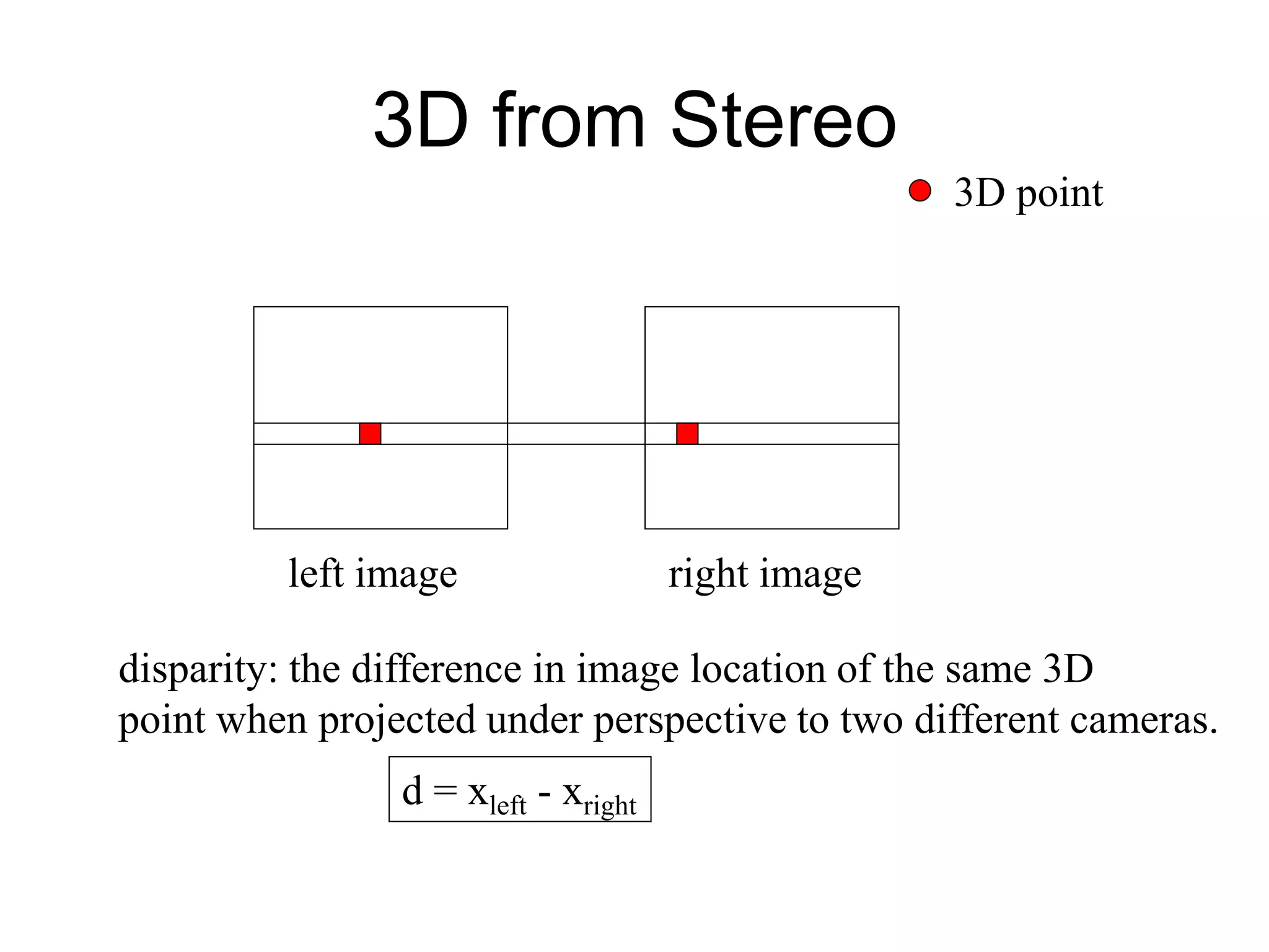
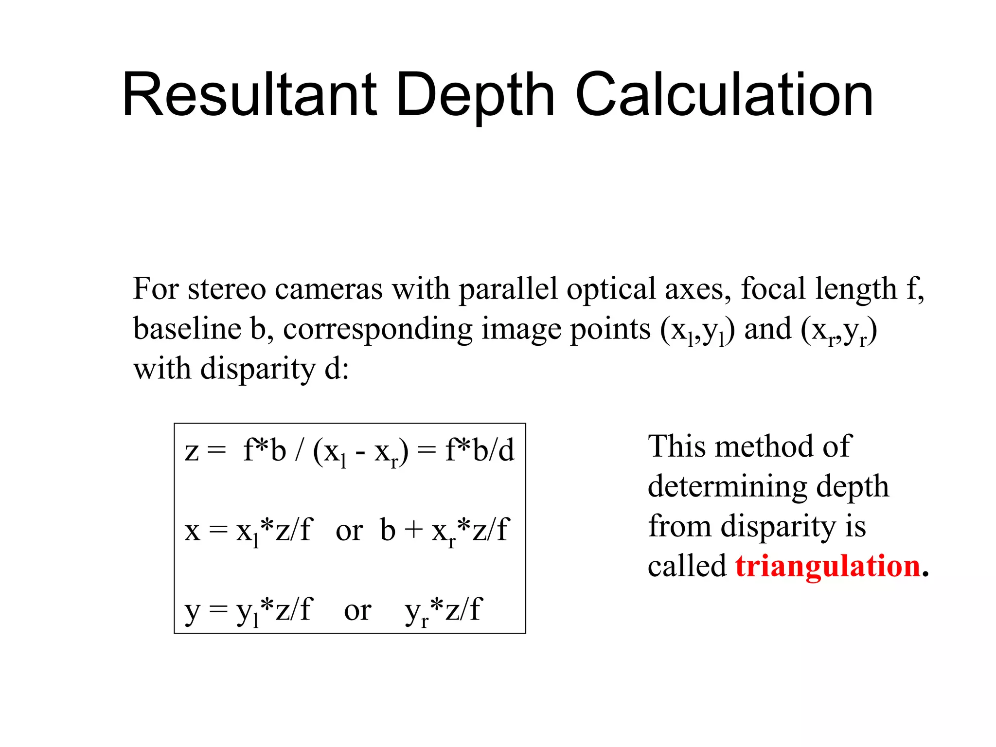
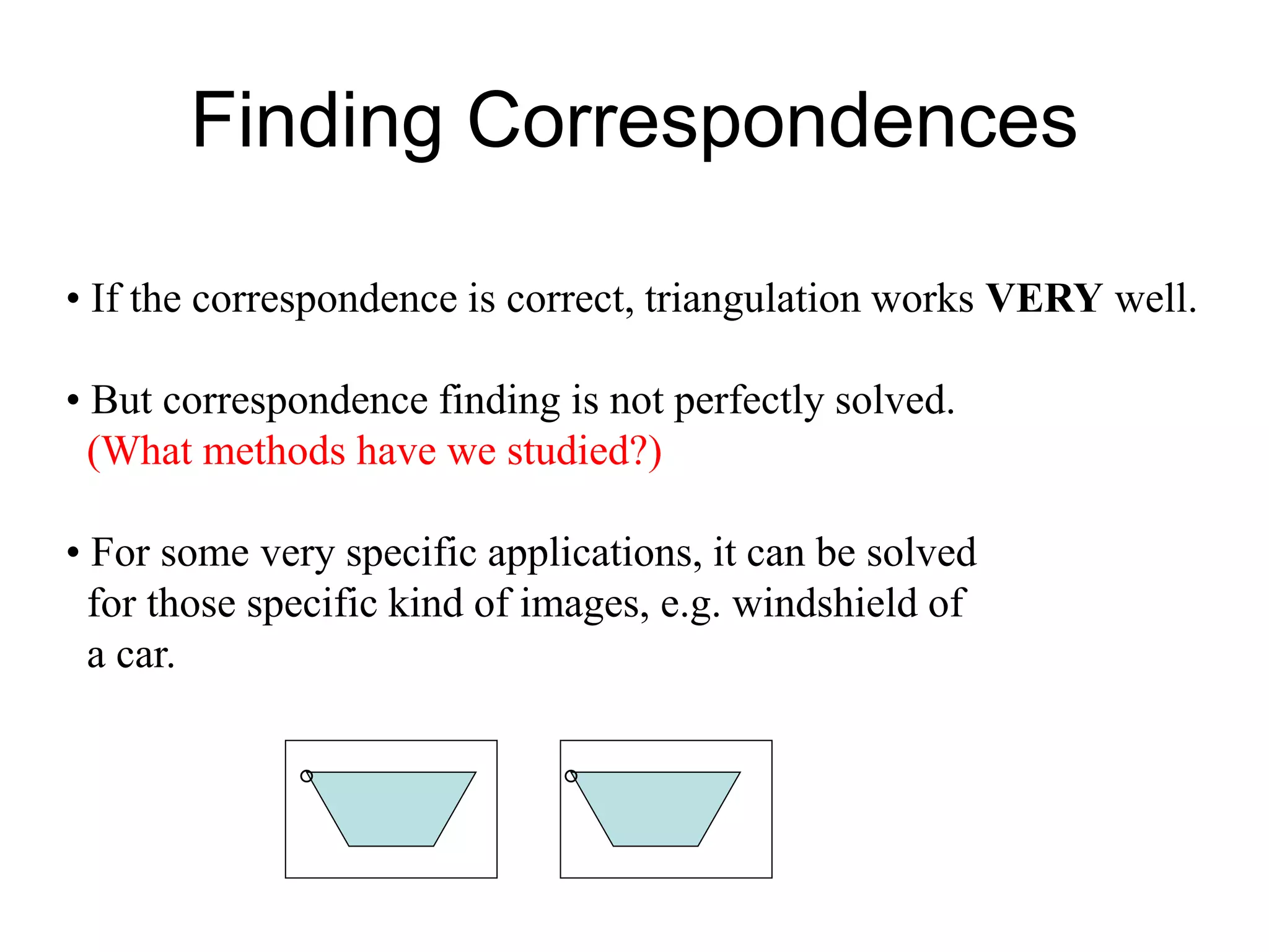
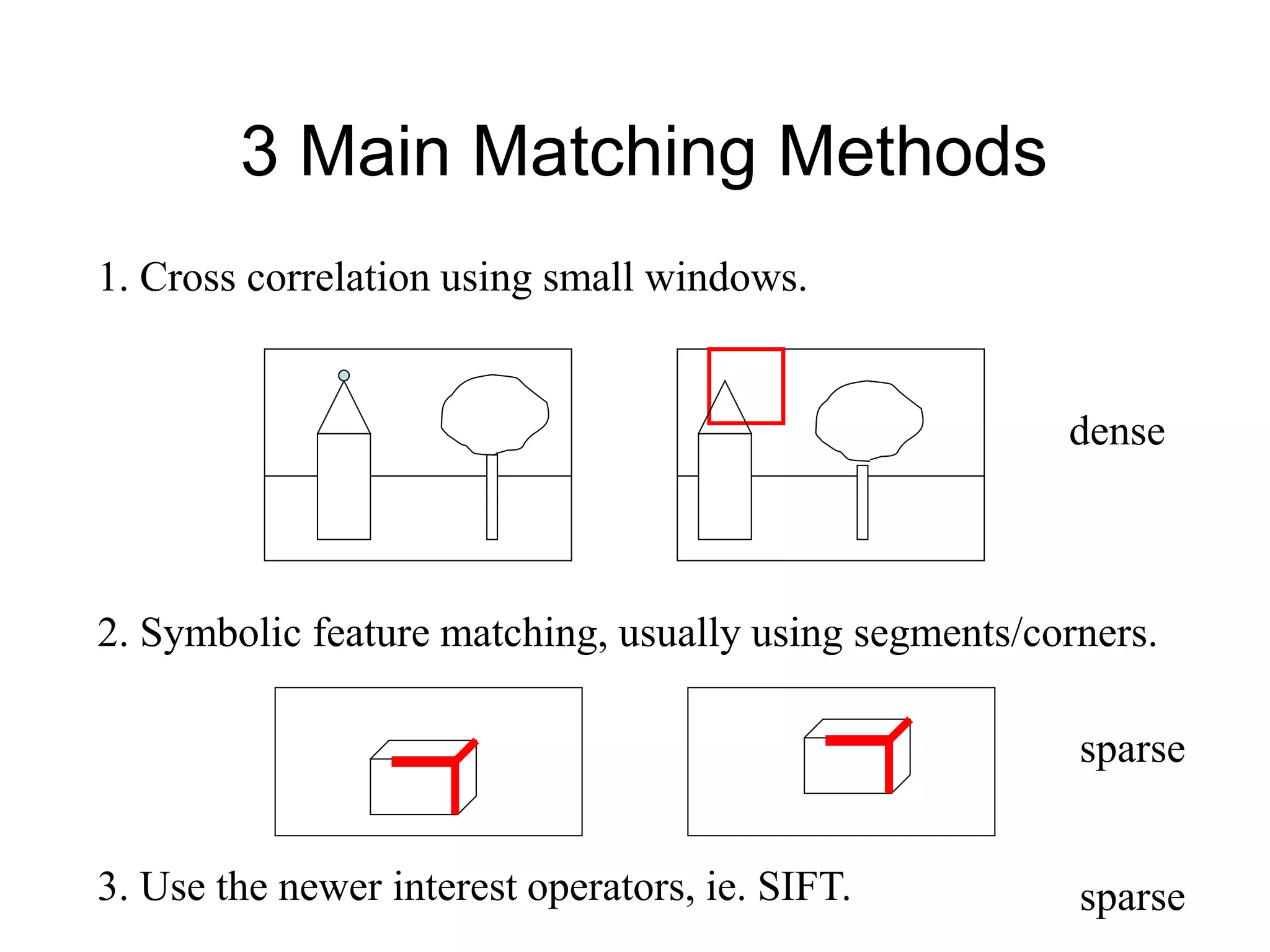
This document discusses 3D sensing and reconstruction techniques including camera models, stereo triangulation, and structured light methods. It covers perspective projection, calibrating camera intrinsics and extrinsics, finding correspondences between stereo images using features or correlation, and reconstructing 3D points through triangulation. The key steps are calibrating cameras, identifying matching points in stereo images, and computing depth from disparity based on each camera's focal length and baseline distance between lenses.


![Structured Light
3D Computation
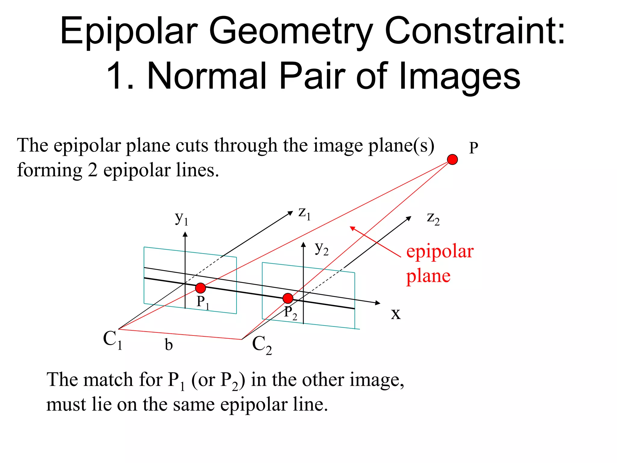
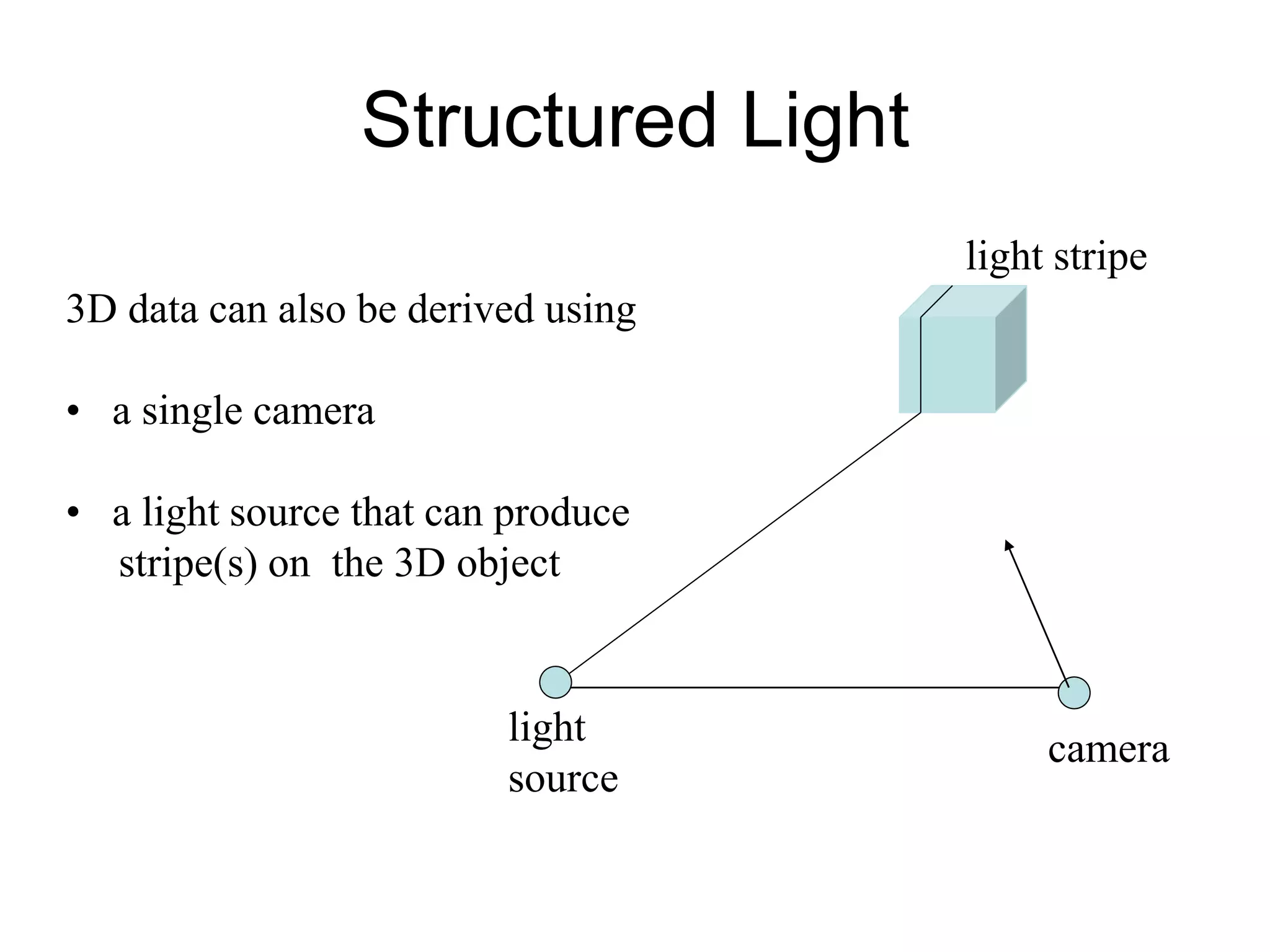
3D data can also be derived using
• a single camera
• a light source that can produce
stripe(s) on the 3D object
light
source
x axis
f
(x´,y´,f)
3D point
(x, y, z)
b
b
[x y z] = --------------- [x´ y´ f]
f cot - x´
(0,0,0)
3D image](https://image.slidesharecdn.com/3dsensing-230201102345-d6e6f24d/75/3DSensing-ppt-14-2048.jpg)


![Extrinsic Parameters
• translation parameters
t = [tx ty tz]
• rotation matrix
r11 r12 r13 0
r21 r22 r23 0
r31 r32 r33 0
0 0 0 1
R = Are there really
nine parameters?](https://image.slidesharecdn.com/3dsensing-230201102345-d6e6f24d/75/3DSensing-ppt-22-2048.jpg)