BLUETOOTH CONTROLLED ROBOCAR

A robot is usually an electro-mechanical machine that is guided by computer and electronic programming. Many robots have been built for manufacturing purpose and can be found in factories around the world. Designing of the latest inverted ROBOT which can be controlling using an APP for android mobile. We are developing the remote buttons in the android app by which we can control the robot motion with them. A smart phone Android operated robot car. Now here is a simple to control our robo car using Bluetooth module HC-05 and AT89S52 microcontroller with our android Smartphone device. The controlling devices of the whole system are a microcontroller. Bluetooth module, DC motors are interfaced to the microcontroller. . The robot in the project can be made to move in all the four directions using the android phone. In achieving the task the controller is loaded with program written using Embedded ‘C’ Languages. Android smart phone controller Bluetooth robot using microcontroller. In our work, move the robot upward, backward, left and right side by the android application such as Bluetooth Controlled Car.

Recommended
More Related Content
What's hot
What's hot (20)
Similar to BLUETOOTH CONTROLLED ROBOCAR
Similar to BLUETOOTH CONTROLLED ROBOCAR (20)
More from Pulkit Singhal
Recently uploaded
Recently uploaded (20)
BLUETOOTH CONTROLLED ROBOCAR
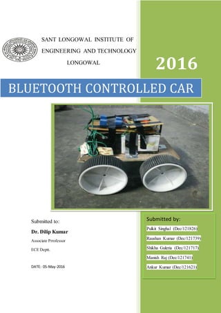
- 1. 1 SANT LONGOWAL INSTITUTE OF ENGINEERING AND TECHNOLOGY LONGOWAL 2016 BLUETOOTH CONTROLLED CAR Submitted by: Pulkit Singhal (Dec/121826) Raushan Kumar (Dec/121739) Shikha Guleria (Dec/121717) Manish Raj (Dec/121741) Ankur Kumar (Dec/121621) Submitted to: Dr. Dilip Kumar Associate Prrofessor ECE Deptt. DATE: 05-May-2016
- 2. 2 SANT LONGOWAL INSTITUTE OF ENGINEERING AND TECHNOLOGY, LONGOWAL BONAFIDE CERTIFICATE This is to certify that the project report entitled “Bluetooth Controlled Rob car” submitted by the students in partial fulfilment of the requirements for the award of the DIPLOMA in “ELECTRONICS AND COMMUNICATION. Engineering is a bonafide record of the work carried out under our guidance and supervision at Sant Longowal Institute of Engineering and Technology. Name of the Supervisor: Name of Co-Supervisor: Dr. Dilip Kumar Er. Savita Mam Associate Professor Er. Sukhbir Singh ECE Deptt. This project report was evaluated by us on 05/05/2016.
- 3. 3 ACKNOWLEDGEMENT We would like to express our gratitude and appreciation to all those who gave us the possibility to complete this report. A special thanks to our Project Coordinator, Dr. Dilip Kumar, whose help, stimulating suggestions and encouragement, helped us to coordinate our project especially in writing this report. I would also like to acknowledge with much appreciation the crucial role of the staff of Laboratory, who gave the permission to use all required machinery and the necessary material to complete the project. A special thanks goes to all team members, who help to assemble the parts and gave suggestion about the Bluetooth Controlled Robocar. Last but not the least I place a deep sense of gratitude to our friends who have been constant source of inspiration during the preparation of this project work. Date: 05-05-2016 Name of Students: Place: Longowal Pulkit Singhal (Dec/121826) Raushan Kumar (Dec/121739) Shikha Guleria (Dec/121717) Manish Raj (Dec/121741) Ankur Kumar (Dec/121621)
- 4. 4 Abstract A robot is usually an electro-mechanical machine that is guided by computer and electronic programming. Many robots have been built for manufacturing purpose and can be found in factories around the world. Designing of the latest inverted ROBOT which can be controlling using an APP for android mobile. We are developing the remote buttons in the android app by which we can control the robot motion with them. And in which we use Bluetooth communication to interface controller and android. Controller can be interfaced to the Bluetooth module though UART protocol. According to commands received from android the robot motion can be controlled. The consistent output of a robotic system along with quality and repeatability are unmatched. Using smart devices in order to control the robots offer a sense of freedom in the world of robots. How Android devices come in different shapes and features, the robots can be designed to fit with any Android devices. In general, some robotic parts are included in almost all simple projects where little robots are controlled with Android devices. These parts are: robot structure (for example car chassis), the controller, Bluetooth module, electric motors, motor driver, and other parts like batteries, power cables, wheels, etc. If you want to focus more on programming and less in electronics and mechanics, a robotic kit is the most useful and easy robot that can be controlled. Most projects including Android controlling robots uses wheeled robots. There is not a rule; you can control any type of robot using just a simple Android device. …
- 5. 5 Table of Content page Bonafied Certificate ii Acknowledgments iii Abstract iv Table of Contents v List of Tables vi List of Figures vii Chapter 1 : Introduction 1 1.1 Block Diagram of the Project 2 Chapter 2: Software 3 2.1 µVision® IDE 3 2.1.1 C51 C Compiler 3 2.2 Proteus 4 2.2.1 Microcontroller Simulation 4 Chapter 3: Hardware 5 3.1 AT89S52 Microcontroller 5 3.1.1 Key Parameter 5 3.1.2 Pin Diagram 6 3.1.3 Pin Description 6 3.2 Bluetooth Module HC-05 9 3.2.1 HC-05 Pin Out 9 3.2.2 Sections of the BT Board 10 3.3 Motor IC ULN2003 11 3.3.1 Driver Description 12 3.3.2 Application 12 3.4 DC Motor 12 volt 13 3.5 OPTOCOUPLER OR VACTROL 14 3.6 Relay 15 3.6.1 Relay Switch 16 3.6.2 Relay application 16 3.7 Battery 17 3.7.1 Exide 12v Battery 17 3.7.2 9v Battery 17
- 6. 6 3.8 LM7805 VOLTAGE REGULATOR 18 Chapter 4: Programming in Embedded C 19 Appendix A A.1 Future Development 21 A.2 Application and Advantage 21 Appendix B: Expenditure 22 References 23
- 7. 7 List of Tables Table Title page 3.1 Pin Description of AT89S51 7 3.2 Port3 Alternate function 8 3.3 Pin Description of ULN2003 11 3.4 Pin Description on 7805 18
- 8. 8 List of Figures Figure Title page 1.1: Block diagram of Bluetooth Controlled Robo-Car 2 1.2: Blue control app as Transmitter 2 2.1 : KIEL μVision 4 3 2.2 : Proteus 4 3.1: Pin Diagram of AT89S52 6 3.2: HC-05 Pin Diagram 9 3.3: HC-05 10 3.4: Pin Diagram of ULN2003 11 3.5: schematic for each driver of IC ULN2003 12 3.6: 12volt DC motor 13 3.7 : Circuit of Vactrol 14 3.8: 12volt Relay 15 3.8: 12volt Relay 16 3.9: Exide 12volt battery 17 3.10: 9volt battery 17 3.11: LM7805 18
- 9. 9 Chapter 1 INTRODUCTION Nowadays smart phones are becoming more powerful with reinforced processors, larger storage capacities, richer entertainment function and more communication methods. Bluetooth is mainly used for data exchange; add new features to smart phones. Bluetooth technology shows its advantage by integrating with smart phones. It has changed how people use digital device at home or office, and has transferred traditional wired digital devices into wireless devices. A host Bluetooth device is capable of communicating with up to seven Bluetooth modules at same time through one link. Considering its normal working area of within eight meters, it is especially useful in home environment. Thank for Bluetooth technology and other similar techniques, with dramatic increase in Smartphone users, smart phones have gradually turned into an all-purpose portable device and provided people for their daily use. In recent years, an open-source platform Android has been widely used in smart phones. Android has complete software package consisting of an operating system, middleware layer and core applications. Different from other existing platform like iOS (iPhone OS), it comes with software development kit (SDK), which provides essential tools and Application. Using a Smartphone as the “brain” of a robot is already an active research field with several open opportunities and promising possibilities. In this paper we present a review of current robots controlled by mobile phone and discuss a closed loop control systems using audio channels of mobile devices, such as phones and tablet computers. In our work, move the robot upward, backward, left and right side by the android application such as Bluetooth Controlled Car.
- 10. 10 1.1 BLOCK DIAGRAM A smart phone Android operated robot car. Now here is a simple to control our robo car using Bluetooth module HC-05 and AT89S52 microcontroller with our android Smartphone device. The controlling devices of the whole system are a microcontroller. Bluetooth module, DC motors are interfaced to the microcontroller. The data receive by the Bluetooth module from android smart phone is fed as input to the controller. The controller acts accordingly on the DC motor of the robot. The robot in the project can be made to move in all the four directions using the android phone. In achieving the task the controller is loaded with program written using Embedded ‘C’ Languages. Android smart phone controller Bluetooth robot using microcontroller.[1] Figure 1.1: Block diagram of Bluetooth Controlled Robo-Car Figure 1.2: Blue control app as Transmitter
- 11. 11 Chapter 2 SOFTWARES 2.1 µVision® IDE The µVision IDE combines project management, run-time environment, build facilities, source code editing, and program debugging in a single powerful environment. µVision is easy-to-use and accelerates your embedded software development. µVision supports multiple screens and allows you to create individual window layouts anywhere on the visual surface. The µVision Debugger provides a single environment in which you may test, verify, and optimize your application code. The debugger includes traditional features like simple and complex breakpoints, watch windows, and execution control and provides full visibility to device peripherals.[2] Figure 2.1 : KIEL μVision 4 2.1.1 C51 C Compiler The Keil C51 C Compiler for the 8051 microcontroller is the most popular 8051 C compiler in the world. It provides more features than any other 8051 C compiler available today. The C51 Compiler allows you to write 8051 microcontroller applications in C that, once compiled, have the efficiency and speed of assembly language. Language extensions in the C51 Compiler give you full access to all resources of the 8051.[3]
- 12. 12 2.2 Proteus Proteus ISIS is the best simulation software in the world for various designs with electronics & microcontroller. It is mainly popular because of availability of almost all microcontrollers in it. So it is a handy tool to test programs and embedded designs for electronics hobbyist & expert. You can simulate your programming of microcontroller in Proteus 8 Simulation Software. After simulating your circuit using Proteus Software you can directly make PCB design with it so it could be an all in one package for students and hobbyists. So I think now you have a little bit idea about what is proteus software.[4] Figure 2.2 : Proteus 2.2.1 Microcontroller Simulation The micro-controller simulation in Proteus works by applying either a hex file or a debug file to the microcontroller part on the schematic. It is then co-simulated along with any analog and digital electronics connected to it. This enables it's used in a broad spectrum of project prototyping in areas such as motor control, temperature control and user interface design.[5]
- 13. 13 Chapter 3 Hardware 3.1 AT89S52 Microcontroller Low-power, high-performance CMOS 8-bit microcontroller with 8KB of ISP flash memory. The device uses Atmel high-density, non-volatile memory technology and is compatible with the industry-standard 80C51 instruction set and pin out. On-chip flash allows the program memory to be reprogrammed in-system or by a conventional non-volatile memory programmer. This powerful microcontroller is suitable for many embedded control applications. 3.1.1 Key Parameters Parameter Value: ROM( Bytes) : 8 K Bytes RAM( Bytes) : 256 Bytes Pin Count : 40 Max. Operating Freq. (MHz) : 24 MHz CPU : 8051-12C Max I/O Pins : 32 UART : 1 Operating Voltage (Vcc) : 4.0 to 5.5 Timers : 3 Interrupt sources : 8 Serial port : 1
- 14. 14 3.1.2 PINDIAGRAM[6] : Figure 3.1: Pin Diagram of AT89S52 3.1.3 PIN DESCRIPTION: ALE/PROG: Address Latch Enable (ALE) is an output pulse for latching the low byte of the address during accesses to external memory. This pin is also the program pulse input (PROG) during Flash programming.
- 15. 15 RST: On the left side the pin 9 is the reset pin. A high on this pin for two machine cycles while the oscillator is running reset the device. If we reset the device then it will start executing the program. VCC: +5 volt. Table 3.1: Pin Description of AT89S51 Port 0: Port 0 is an 8-bit open drain bidirectional I/O port. As an output port, each pin can sink eight TTL inputs. When 1s are written to port 0 pins, the pins can be used as high impedance inputs. Ports 0 can also be configured to the multiplexed low order address/data bus during accesses to external program and data memory. In this mode, P0 has internal pull-ups.. External pull-ups are required during program verification. Port 1: Port 1 is an 8-bit bidirectional I/O port with internal pull-ups. The Port 1 output buffers can sink/source four TTL inputs. When 1s are written to Port 1 pins, they are pulled high by the internal pull-ups and can be used as inputs In addition, P1.0 and P1.1 can be configured to be the timer/counter 2 external count input (P1.0/T2) and the timer/counter 2 trigger input (P1.1/T2EX), respectively. Port 1 also receives the low-order address bytes during Flash programming and verification.
- 16. 16 Port 2: Port 2 is an 8-bit bidirectional I/O port with internal pull-ups. The Port 2 output buffers can sink/source four TTL inputs. When 1s are written to Port 2 pins, they are pulled high by the internal pull-ups and can be used as inputs. Port 2 uses strong internal pull-ups when emitting 1s.During accesses to external data memory that uses 8-bit addresses (MOVX @ RI), Port 2emits the contents of the P2 Special Function Register. Port 2 also receives the high-order address bits and some control signals during Flash programming and verification. Port 3 Port 3 is an 8-bit bidirectional I/O port with internal pull-ups. The Port 3 output buffers can sink/source four TTL inputs. When 1s are written to Port 3 pins, they are pulled high by the internal pull-ups and can be used as inputs. As inputs, Port 3 pins that are externally being pulled low will source current (IIL) because of the pull-ups. Port 3receives some control signals for Flash programming and verification. Port 3 also serves the functions of various special features of the AT89S52, as shown in the following table Table 3.2 : Port3 Alternate function Port 3 also receives some control registers for flash programming and programming verification.
- 17. 17 3.2 Bluetooth Module HC-05: HC-05 module is an easy to use Bluetooth module, designed for transparent wireless serial connection setup. It is a wireless technology standard for exchanging data over short distances (using short-wavelength UHF radio waves in the ISM band from 2.4 to 2.485 GHz) from fixed and mobile devices, and building Personal Area Networks (PANs). Range is approximately 10 Meters (30 feet)[7]. Figure 3.2: HC-05 Pin Diagram 3.2.1 HC-05 Pin Out : EN: If brought HIGH before power is applied, forces AT Command Setup Mode. LED blinks slowly (2 seconds) VCC: +5 Power GND: System / 8051 Ground TXD: Transmit Serial Data from HC-05 to 8051 Serial Receive. RXD: Receive Serial Data from 8051 Serial Transmit STATE: Tells if connected or not.
- 18. 18 3.2.2 Sections of the BT Board (Below): The Green HC-05 sub-module is soldered on top of the Blue BT Board The HC-05 module includes the Radio and Memory chips, 26 MHz crystal, antenna and RF matching network. The right section of the BT Board has connection pins for power and signals as well as a 5V to 3.3V Regulator, LED, and level shifting. Figure 3.3: HC-05
- 19. 19 3.3 Motor IC ULN2003 ULN2003 is a high voltage and high current Darlington array IC. It contains seven open collector darlington pairs with common emitters. A darlington pair is an arrangement of two bipolar transistors[8] . ULN2003 belongs to the family of ULN200X series of ICs. Different versions of this family interface to different logic families. ULN2003 is for 5V TTL, CMOS logic devices. These ICs are used when driving a wide range of loads and are used as relay drivers, display drivers, line drivers etc. ULN2003 is also commonly used while driving Stepper Motors. Figure 3.4: Pin Diagram of ULN2003 [9] Table 3.3: Pin Description of ULN2003
- 20. 20 3.3.1Driver Description Each channel or darlington pair in ULN2003 is rated at 500mA and can withstand peak current of 600mA. The inputs and outputs are provided opposite to each other in the pin layout. Each driver also contains a suppression diode to dissipate voltage spikes while driving inductive loads. The schematic for each driver is given below: Figure 3.5: schematic for each driver of IC ULN2003 3.3.2 APPLICATIONS: There are many applications of relay driver circuit using uln2003, but some of famous applications are given below: relay drivers circuits motor drivers circuits lamp drivers line drivers hammer drivers logic buffers and many others
- 21. 21 3.4 DC MOTOR 12 VOLT 300 RPM Side Shaft Heavy Duty DC Gear Motor is suitable for large robots / automation systems. It has sturdy construction with gear box built to handle stall torque produced by the motor. Drive shaft is supported from both sides with metal bushes. Motor runs smoothly from 4V to 12V and gives 300 RPM at 12V. Motor has 8mm diameter, 17.5mm length drive shaft with D shape for excellent coupling[10]. Figure 3.6: 12volt DC motor Specifications RPM: 300 at 12V Voltage: 4V to 12V Stall torque: 23Kg-cm at stall current of 8.4A@12V Shaft diameter: 8mm Shaft length: 17.5mm Brush type: Carbon Motor weight: 280gms
- 22. 22 3.5 OPTOCOUPLER OR VACTROL In electronic, an optocoupler, also called an vactrol, opto-isolator, photocoupler, or optical isolator, is a component that transfers electrical signals between two isolated circuits by using light[11]. (LED + LDR)Tape = Vactrol. A Vactrol is an opto-isolator device used for channel switching amplifiers. Opto-isolators prevent high voltages from affecting the system receiving the signal[12]. Figure 3.7 : Circuit of Vactrol Opto-couplers or Vactrol , are made up of a light emitting device, and a light sensitive device, all wrapped up in one package, but with no electrical connection between the two, just a beam of light. The light is emitter is nearly by a LED. The light sensitive device may be a photodiode, phototransistor, or more esoteric devices such as thyristors, TRIACs etc[13].
- 23. 23 3.6 Relay A relay is an electrically operated switch. We know that most of the high end industrial application devices have relays for their effective working. Relays are switches which are operated both electrically and mechanically. Relays consist of an electromagnet and also a set of contacts. The switching mechanism is carried out with the help of the electromagnet. There are also other operating principles for its working. But they differ according to their applications. Most of the devices have the application of relays[14]. Figure 3.8: 12volt Relay [15] The main operation of a relay comes in places where only a low-power signal can be used to control a circuit. It is also used in places where only one signal can be used to control a lot of circuits. Normally relay are of two types: 1) Normally-Open(NO) : The circuit is disconnected i.e. open when the relay is inactive. 2) Normally-Closed(NC) : The circuit is connected i.e. closed when the relay is inactive.
- 24. 24 3.6.1 Relay Switch A relay switch can be divided into two parts: input and output. The input section has a coil which generates magnetic field when a small voltage from an electronic circuit is applied to it. This voltage is called the operating voltage. Commonly used relays are available in different configuration of operating voltages like 6V, 9V, 12V, 24V etc. The output section consists of contactors which connect or disconnect mechanically[16]. In a basic relay there are three contactors: normally open (NO), normally closed (NC) and common (COM). At no input state, the COM is connected to NC. When the operating voltage is applied the relay coil gets energized and the COM changes contact to NO. Different relay configurations are available like SPST, SPDT, etc, which have different number of changeover contacts. By using proper combination of contactors, the electrical circuit can be switched on and off. Figure 3.8: 12volt Relay 3.6.2 Relay Applications Relays are used to realize logic functions. They play a very important role in providing safety critical logic. Relays are used to provide time delay functions. They are used to time the delay open and delay close of contacts. Relays are used to control high voltage circuits with the help of low voltage signals. They are also used as protective relays. By this function all the faults during transmission and reception can be detected and isolated.
- 25. 25 3.7 Battery 3.7.1 Exide 12 volt Battery[17] The Exide EP 7-12volt rechargeable battery is a high quality battery designed to provide excellent performance, durability and long life. Chemical Composition: Lead Acid Battery Load: 12 Volts 7 AH Battery Type: Lead Acid SMF (Sealed Maintenance Free) Uses: UPS, Mini Projects, Mini Invertors, Solar Equipments. Figure 3.9: Exide 12volt battery 3.7.2 Nine Volt Battery[18] The nine-volt battery, or 9-volt battery, It is an affordable, reliable, dedicated low-power solution to provide sufficient energy to your application. Ideally used in circuits with lowpower consumption so that it can work for longer durations. Figure 3.10: 9volt battery
- 26. 26 3.8 LM7805 VOLTAGE REGULATOR 7805 is a voltage regulator integrated circuit. It is a member of 78xx series of fixed linear voltage regulator ICs. The voltage source in a circuit may have fluctuations and would not give the fixed voltage output. The voltage regulator IC maintains the output voltage at a constant value. The xx in 78xx indicates the fixed output voltage it is designed to provide. 7805 provides +5V regulated power supply[19]. Figure 3.11: LM7805 Pin Description: Table 3.4: Pin Description on 7805
- 27. 27 Chapter 4 Programming in Embedded C Programming #include<reg52.h> sbit motor_pin_1 = P2^0; sbit motor_pin_2 = P2^1; sbit motor_pin_3 = P2^2; sbit motor_pin_4 = P2^3; unsigned char c; void main() { P2=0xFF; //set Port 2 to high TMOD=0X20; TH1=0XFD; TL1=0X00; SCON=0X50; TR1=1; while(1) { while(RI==0); c=SBUF; RI=0; if(c=='U') //move forward { motor_pin_1 = 0; motor_pin_2 = 1; motor_pin_3 = 0;
- 28. 28 motor_pin_4 = 1; } else if (c=='D') //move backward { motor_pin_1 = 1; motor_pin_2 = 0; motor_pin_3 = 1; motor_pin_4 = 0; } else if (c=='R') { motor_pin_1 = 0; motor_pin_2 = 1; motor_pin_3 = 0; motor_pin_4 = 0; } else if (c=='L') { motor_pin_1 = 0; motor_pin_2 = 0; motor_pin_3 = 1; motor_pin_4 = 0; } else if (c=='C') P2=0xFF; // motor stop } }
- 29. 29 Appendix A A.1 Future Development: The knowledge is ever expanding and so are the problems which the mankind strive to solve. In this spirit, it is hoped that the current activity will lead to further enhancements . 1. We can interface sensors to this robot so that it can monitor some parameters. 2. We can add wireless camera to this robot. 3. We can control the speed of car. A.2 Applications and Advantages: 1. The robot is small in size so can be used for spying. 2. With few additions and modifications, this robot can be used in the borders for detecting and disposing hidden land mines. 3. The robot can be used for reconnaissance or surveillance.
- 30. 30 Appendix B EXPENDITURE OF PROJECT S.NO COMPONENTS No. of Pieces AMOUNT (INR) 1. 2. 3. 4. 5. 6. 7. 8. 9. 10. 11. 12. 13. 14. 15. 16. AT89S52 Bluetooth HC-05 Wooden Chassis 12 VOLT DC MOTOR Wheel ULN2003 PCB 7805 LDR LED Relay 12 volt dc battery 9 volt dc battery Crystal Oscillator Travelling Extra 1 1 1 4 4 1 2 1 4 4 4 1 1 1 90 650 250 1800 400 12 30 10 40 8 80 800 15 15 250 100 Total 4550
- 31. 31 References [1] www.ijser.in/archives/v2i7/SjIwMTMzMjQ=.pdf [2] http://www2.keil.com/mdk5/uvision/ [3] http://www.keil.com/c51/c51.asp [4] http://ismtechbd.com/what-is-proteus/ [5] https://en.wikipedia.org/wiki/Proteus_Design_Suite [6] https://www.scribd.com/doc/31837053/28/PIN-DESCRIPTION-OF-AT89S52 [7] https://arduino-info.wikispaces.com/BlueTooth-HC05-HC06-Modules-How-To [8] http://www.engineersgarage.com/electronic-components/uln2003-datasheet [9] http://www.piccircuit.com/shop/ics-drivers/10 [10] http://www.nex-robotics.com/products/motors-and-accessories/300-rpm-side-shaft- heavy-duty-dc-gear-motor.html [11] https://en.wikipedia.org/wiki/Opto-isolator [12] http://www.electronics-lab.com/super-simple-vactrol-construction/ [13] https://www.elprocus.com/opto-couplers-types-applications [14] http://www.circuitstoday.com/working-of-relays [15] http://www.lelong.com.my/srd-12v-dc-10a-5-pin-relay-mcs123-167817438-2016-09- Sale-P.htm [16] http://www.engineersgarage.com/electronic-components/relays [17] http://www.amazon.in/12v-Exide-PowerSafe-Battery-Sealed/dp/B00SA1HNZG [18] https://www.fabtolab.com/Hi-Watt-9V-6F22M-battery [19] http://www.engineersgarage.com/electronic-components/7805-voltage-regulator-ic [20]www.google.co.in