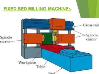
BABARIA INSTITUTE OF
TECHNOLOGY
TOPIC:-
Milling Machine
GROUP MEMBERS:-
 Pragnesh Choudhary(170050119011)
 Vivek Dhiman (170050119012)
 RahulE.Ranjabhooshan (170050119013)
 Pankaj Gadhvi (170050119014)
CONTENT:
 Introductionof millingmachine
 Principle of millingmachine
 Typesof milling machine
 Indexing
 Milling machineoperation
Milling:-
• It is a metal cutting operation in which the excess material from the
work piece is removed by rotating multipoint cutting tool called milling
cutter.
• A millingmachineis a machine tool that removes metal as the work is
fed against a rotating multipoint cutter.
• The milling cutter rotates at high speed and it removes metal at a very
fast rate with the help of multiple cutting edges.
• One or more number of cutters can be mounted simultaneously on the
milling machine.
• This is the reason that a milling machine finds wide application in
production work.
 As the workpiece moves against the cutting edges of milling cutter, metal is
removed in form chips
 Machined surface is formed in one or more passes of the work.
 The work to be machined is held in a vice, a rotary table, a three jaw
chuck, an index head, in a special fixture or bolted to machine table.
 In many applications, due to its higher production rate and accuracy,
milling machine has even replaced shapers and slotters.
MILLING METHODS:-
Twobasic methods of milling
1.Up-milling or conventional milling
2.Down-milling or climb milling
1.Up-millingor conventionalmilling:-
 Metal is removed by cutter rotating against
the direction of travel of the workpiece.
 Needs stronger holding of the job.
 Chip thickness is minimum at the start of cut
and maximum at the end of the cut.
 Disadvantage- tendency to lift work from the fixtures and poor surface finish.
UP MILLING(CONVENTIONAL MILLING):-
2.Down-millingor climbmilling:-
 Metal is removed by cutter rotating in the same
direction of travel of the workpiece.
 teeth cut downward instead of upwards.
 Chip thickness is maximum at the start of cut and
minimum at the end of cut.
 Less friction involved
 Better surface finish.
 Less power consumption.
DOWN MILLING(CLIMB MILLING)
PRINCIPLE PARTS:-
 Base
 Column
 Knee
 Saddle
 Table
 Spindle
TYPES OF MILLING MACHINE:-
 The milling machine may be classified in several forms, but the choice
of any particular machine is determined primarily by the size of the
workpiece.
 According to general design, the distinctive types of
milling machines are:-
1. Column and knee type milling machines
2. Planer milling machine
3. Fixed-bed type milling machine
4. Special types of milling machines
COLUMN AND KNEE TYPE:-
 It is the most commonly used milling machine
used for general shop work.
 The table is mounted on the knee which in
turn is mounted on the vertical slides of the
main column.
 The knee is vertically adjustable on the column
so that the table can be moved up and down
to accommodate work of various heights.
CLASSIFIACTION OF COLUMN & KNEE
TYPE MILLING MACHINE
a) Verticalmillingm/c.
b) Horizontalmillingm/c.
c) Universalmillingm/c.
(a) Horizontal Millingmachine:-
• The horizontal milling machine has a spindle that is
parallel to the shop floor and an overarm that
extends over the workpiece.
• The overarm supports the arbor, which holds the
milling cutter.
• On the horizontal mill, the arbor is the component that
rotates the milling cutter.
ACTUAL HORIZONTAL MILLING MACHINE:-
(B) VERTICAL MILLING MACHINE:-
 Spindle is vertical or perpendicular to the worktable.
 It has all the movements of the table for propersetting and feeding the
work.
 Spindle head may be swiveled at an angle, permitting the milling cutter
mounted on the spindle to work onangular surfaces.
 In some machines, spindle can also be adjusted upor down relative
to the work.
 Adopted for machining grooves, slots and flat surfaces.
VERTICAL MILLING
MACHINE
MAJOR PARTS :
1. BASE
2. COLUMN
3. SPINDLE
4. SPINDL
E HEAD
5. KNEE
6. SADDLE
7. WORKTABLE
(C) UNIVERSAL MILLING MACHINE:-
 Difference from plain horizontal machine
is addition of table swivel housing
Permits table to be swiveled 45º in either
direction in a horizontal plane
 Used for milling of helical grooves
in twist drills, milling cutters, and
gears
2. Fixed-bed type milling
machine
 Comparatively large, heavy and rigid and differ from column and knee type milling
machines.
 Tableis directly mounted on fixed bed.
 No provision is provided for cross or vertical adjustment of
the table.
 The cutter mounted on the spindle head may be moved vertically on the column and the
spindle may be adjusted horizontally to provide cross adjustment.
 Three types:-
1. Simplex 2. duplex 3. triplex
FIXED BED MILLING MACHINE:-
3. PLANER MILLING MACHINE:-
 Looks like double column planermachine.
 Milling heads mounted in various planes, verticalheads on the cross-
rail and horizontal heads at the sides (on column)
 This arrangement enables it to machine a workpieceon several sides
simultaneously.
 Used for producing long straight surfaces on largeand heavy
machine parts.
4. SPECIAL-TYPE MACHINES:-
 Designed for individual milling operations Used for only one
particular type of job.
 Completely automatic Employed when hundreds or thousands of similar
pieces are to be machined.
 Tracermills(Profilingmilling machines):
 Also calledduplicators
 Designed to reproduce an irregular part geometry that can be created on an
template
 In two dimensions- tracer
 In three dimensions- duplicator
Examples:-
 CNC milling machines:
 - Cutter path controlled by numerical data
 - Suited to profile, pocket, surface
contouring.
Indexing:-
 BasicallyIndexingisthe operation dividingthe peripheryofthe
 Workpieceinto anynumberof equaldivisionsbyusingindexinghead.
Indexing head part:-
Methods of indexing;-
 Directindexing
 PlainorSimpleindexing
 Compoundindexing
 Differentialindexing
 Angularindexing
Direct Indexing:-
 Simplest form of indexing.
 Performed by disengaging wormshaft from worm wheel by means of
eccentric device in dividinghead.
 Spring-loaded tongue lock engages numbered slots in index plate.
 Used for quick indexing ofworkpiece when cutting flutes, hexagons,
squares, etc.
 Direct indexing plate usuallycontains three sets of hole circles or slots: 24,
30, and 36.
Plain indexing:-
 Work positioned by means ofcrank, index plate, and sector arms
 Worm attached to crank must be engaged with worm wheel on dividing head spindle
 40 teeth on worm wheel.
 One complete turn on index crank cause spindle and work to rotate one-fortieth of a turn
(ratio of 40:1)
 Calculating the indexing or number of turns of crank for most divisions,simply divide 40 by
number of divisions to be cut or:-
Indexing=40/N
where N=noof equaldivisionmade on workpiece
Compound indexing:-
 The principle of compound indexing is essentially the same as that for simple
indexing except that compound indexing uses two different circles of one plates to
obtain a crank movement not obtainable with plain indexing.
 Twostepprocedure for compound indexing is as follow:-
1) Rotate the crank or handle in the usual way to obtain a movement of n1, hole
space in an N1 hole circle by keeping the index plate fixed.
2) Release the back pin and rotate the index plate with handle to obtain a
movement ofn2 hole space in an N2 hole of the index plate in the same or
opposite direction.
Angular indexing:-
 Setup for simple indexing maybe used.
 Must calculate indexing with angular distance between
divisions instead number of divisions.
 One complete turn of indexcrank turns work 1/40 of a
turn.
 1/40 of 360º equals 9 degrees.
Indexingindegrees=
no.of degreesrequired
9
Differential indexing:-
 Used when 40/N cannot be reduced toa factor of one of the available hole
circles.
 Index plate must be revolved either forward or backward part of a turnwhile
index crank turned to attain proper spacing (indexing).
 Change of rotation effected by idler gear or gears in gear train.
MILLING OPERATIONS:-
 Plain or slab milling
 Face milling
 End milling
 Side milling
 Slot milling
 Angular milling
 Form milling
 Straddle milling
 Slitting or sawmilling
 Gear cutting
 Key way milling
 String milling
 Profile milling
 Threadmilling
 Helicalmilling
 Cam milling
PLAIN/SURFACE/ SLAB
MILLING PlainMilling:
Process to get the flat surface on the
work piece in which the cutter axis
and work piece axis are parallel. The
primary motion is the rotation of the
cutter. The feed is imparted to the
work piece.
Cutter:Plain millingcutter.
Machine:Horizontal
Milling m/c.
Work piece
Plainmilling cutter
FACE MILLING
FaceMilling:
out forOperation carried
producing a flat surface,
which is perpendicular to the axis of
rotating cutter.
Cutter:Face milling cutter.
Machine:VerticalMilling Machine
MANUFACTURING TECHNOLOGY
END MILLING
FIG. ENDMILLING
EndMilling:
Operation performed for producing
flat surfaces, key slots, grooves or
finishing the edges of the work piece.
Cutter: End milling cutter.
Machine: VerticalMilling
Machine
SIDE MILLING
SIDEMILLING: Operation performed
for producingflat surfaces, slots,
grooves or finishing the edges of the
work piece.
Cutter: End millingcutter.
Machine: Horizontal Milling Machine
SLOT MILLING
FIG. T-SLOTMILLING
Slot Milling: Operation
Of producing slots like
T-slots, plain slots etc.,
Cutter: End milling cutter,
T-slot cutter, side milling
cutter
Machine:Vertical Milling
Machine
ANGULAR MILLING
FIG. ANGULARMILLING
AngularMilling:
Operation of producing all
types of angular cuts like V-notches,groves,
etc…
Cutter:Double angle cutter.
Machine:Horizontal Milling Machine
FORM MILLING
Form Milling:
Operation of producing
all types of angular cuts
andlike V-notches grooves, serrations
and angular surfaces.
Cutter: Double angle cutter.
Machine:Horizontal Milling
Machine
FORM MILLING
STRADDLE MILLING
FIG. STRADDLE MILLING
StraddleMilling:
Operation of machining two
surfaces on a workparallel
simultaneously piece.
Cutter: 2 or more side & face
milling cutters
Machine:Horizontal
MillingMachine
GANG MILLING
FIG. GANG MILLING
GangMilling:
Process to get different profiles
on the work piece
simultaneously with two or more
cutters at one stretch.
Cutter:Different cutters as
required.
Machine:Horizontal Milling
Machine
Profile milling
 Outside periphery of
flat part is cut.
 Conventional end mill
is used to cut the
outside or inside
periphery of a flat
part.
Another form of
end milling used
to mill shallow
pockets into flat
parts
Pocket Milling
SURFACE CONTOURING
Ball - nose cutter is fed
back and forth across
the work along a
curvilinear path at close
intervals to createa three
dimensional surface.
Final milling machine ppt..

Final milling machine ppt..

  • 1.
  • 2.
    GROUP MEMBERS:-  PragneshChoudhary(170050119011)  Vivek Dhiman (170050119012)  RahulE.Ranjabhooshan (170050119013)  Pankaj Gadhvi (170050119014)
  • 3.
    CONTENT:  Introductionof millingmachine Principle of millingmachine  Typesof milling machine  Indexing  Milling machineoperation
  • 4.
    Milling:- • It isa metal cutting operation in which the excess material from the work piece is removed by rotating multipoint cutting tool called milling cutter. • A millingmachineis a machine tool that removes metal as the work is fed against a rotating multipoint cutter. • The milling cutter rotates at high speed and it removes metal at a very fast rate with the help of multiple cutting edges. • One or more number of cutters can be mounted simultaneously on the milling machine. • This is the reason that a milling machine finds wide application in production work.
  • 5.
     As theworkpiece moves against the cutting edges of milling cutter, metal is removed in form chips  Machined surface is formed in one or more passes of the work.  The work to be machined is held in a vice, a rotary table, a three jaw chuck, an index head, in a special fixture or bolted to machine table.  In many applications, due to its higher production rate and accuracy, milling machine has even replaced shapers and slotters.
  • 7.
    MILLING METHODS:- Twobasic methodsof milling 1.Up-milling or conventional milling 2.Down-milling or climb milling
  • 8.
    1.Up-millingor conventionalmilling:-  Metalis removed by cutter rotating against the direction of travel of the workpiece.  Needs stronger holding of the job.  Chip thickness is minimum at the start of cut and maximum at the end of the cut.  Disadvantage- tendency to lift work from the fixtures and poor surface finish.
  • 9.
  • 10.
    2.Down-millingor climbmilling:-  Metalis removed by cutter rotating in the same direction of travel of the workpiece.  teeth cut downward instead of upwards.  Chip thickness is maximum at the start of cut and minimum at the end of cut.  Less friction involved  Better surface finish.  Less power consumption.
  • 11.
  • 13.
    PRINCIPLE PARTS:-  Base Column  Knee  Saddle  Table  Spindle
  • 14.
    TYPES OF MILLINGMACHINE:-  The milling machine may be classified in several forms, but the choice of any particular machine is determined primarily by the size of the workpiece.  According to general design, the distinctive types of milling machines are:- 1. Column and knee type milling machines 2. Planer milling machine 3. Fixed-bed type milling machine 4. Special types of milling machines
  • 15.
    COLUMN AND KNEETYPE:-  It is the most commonly used milling machine used for general shop work.  The table is mounted on the knee which in turn is mounted on the vertical slides of the main column.  The knee is vertically adjustable on the column so that the table can be moved up and down to accommodate work of various heights.
  • 16.
    CLASSIFIACTION OF COLUMN& KNEE TYPE MILLING MACHINE a) Verticalmillingm/c. b) Horizontalmillingm/c. c) Universalmillingm/c.
  • 17.
    (a) Horizontal Millingmachine:- •The horizontal milling machine has a spindle that is parallel to the shop floor and an overarm that extends over the workpiece. • The overarm supports the arbor, which holds the milling cutter. • On the horizontal mill, the arbor is the component that rotates the milling cutter.
  • 19.
  • 20.
    (B) VERTICAL MILLINGMACHINE:-  Spindle is vertical or perpendicular to the worktable.  It has all the movements of the table for propersetting and feeding the work.  Spindle head may be swiveled at an angle, permitting the milling cutter mounted on the spindle to work onangular surfaces.  In some machines, spindle can also be adjusted upor down relative to the work.  Adopted for machining grooves, slots and flat surfaces.
  • 21.
    VERTICAL MILLING MACHINE MAJOR PARTS: 1. BASE 2. COLUMN 3. SPINDLE 4. SPINDL E HEAD 5. KNEE 6. SADDLE 7. WORKTABLE
  • 22.
    (C) UNIVERSAL MILLINGMACHINE:-  Difference from plain horizontal machine is addition of table swivel housing Permits table to be swiveled 45º in either direction in a horizontal plane  Used for milling of helical grooves in twist drills, milling cutters, and gears
  • 23.
    2. Fixed-bed typemilling machine  Comparatively large, heavy and rigid and differ from column and knee type milling machines.  Tableis directly mounted on fixed bed.  No provision is provided for cross or vertical adjustment of the table.  The cutter mounted on the spindle head may be moved vertically on the column and the spindle may be adjusted horizontally to provide cross adjustment.  Three types:- 1. Simplex 2. duplex 3. triplex
  • 24.
  • 25.
    3. PLANER MILLINGMACHINE:-  Looks like double column planermachine.  Milling heads mounted in various planes, verticalheads on the cross- rail and horizontal heads at the sides (on column)  This arrangement enables it to machine a workpieceon several sides simultaneously.  Used for producing long straight surfaces on largeand heavy machine parts.
  • 27.
    4. SPECIAL-TYPE MACHINES:- Designed for individual milling operations Used for only one particular type of job.  Completely automatic Employed when hundreds or thousands of similar pieces are to be machined.  Tracermills(Profilingmilling machines):  Also calledduplicators  Designed to reproduce an irregular part geometry that can be created on an template  In two dimensions- tracer  In three dimensions- duplicator
  • 28.
    Examples:-  CNC millingmachines:  - Cutter path controlled by numerical data  - Suited to profile, pocket, surface contouring.
  • 29.
    Indexing:-  BasicallyIndexingisthe operationdividingthe peripheryofthe  Workpieceinto anynumberof equaldivisionsbyusingindexinghead.
  • 30.
  • 31.
    Methods of indexing;- Directindexing  PlainorSimpleindexing  Compoundindexing  Differentialindexing  Angularindexing
  • 32.
    Direct Indexing:-  Simplestform of indexing.  Performed by disengaging wormshaft from worm wheel by means of eccentric device in dividinghead.  Spring-loaded tongue lock engages numbered slots in index plate.  Used for quick indexing ofworkpiece when cutting flutes, hexagons, squares, etc.  Direct indexing plate usuallycontains three sets of hole circles or slots: 24, 30, and 36.
  • 33.
    Plain indexing:-  Workpositioned by means ofcrank, index plate, and sector arms  Worm attached to crank must be engaged with worm wheel on dividing head spindle  40 teeth on worm wheel.  One complete turn on index crank cause spindle and work to rotate one-fortieth of a turn (ratio of 40:1)  Calculating the indexing or number of turns of crank for most divisions,simply divide 40 by number of divisions to be cut or:- Indexing=40/N where N=noof equaldivisionmade on workpiece
  • 34.
    Compound indexing:-  Theprinciple of compound indexing is essentially the same as that for simple indexing except that compound indexing uses two different circles of one plates to obtain a crank movement not obtainable with plain indexing.  Twostepprocedure for compound indexing is as follow:- 1) Rotate the crank or handle in the usual way to obtain a movement of n1, hole space in an N1 hole circle by keeping the index plate fixed. 2) Release the back pin and rotate the index plate with handle to obtain a movement ofn2 hole space in an N2 hole of the index plate in the same or opposite direction.
  • 35.
    Angular indexing:-  Setupfor simple indexing maybe used.  Must calculate indexing with angular distance between divisions instead number of divisions.  One complete turn of indexcrank turns work 1/40 of a turn.  1/40 of 360º equals 9 degrees. Indexingindegrees= no.of degreesrequired 9
  • 36.
    Differential indexing:-  Usedwhen 40/N cannot be reduced toa factor of one of the available hole circles.  Index plate must be revolved either forward or backward part of a turnwhile index crank turned to attain proper spacing (indexing).  Change of rotation effected by idler gear or gears in gear train.
  • 37.
    MILLING OPERATIONS:-  Plainor slab milling  Face milling  End milling  Side milling  Slot milling  Angular milling  Form milling  Straddle milling
  • 38.
     Slitting orsawmilling  Gear cutting  Key way milling  String milling  Profile milling  Threadmilling  Helicalmilling  Cam milling
  • 39.
    PLAIN/SURFACE/ SLAB MILLING PlainMilling: Processto get the flat surface on the work piece in which the cutter axis and work piece axis are parallel. The primary motion is the rotation of the cutter. The feed is imparted to the work piece. Cutter:Plain millingcutter. Machine:Horizontal Milling m/c.
  • 40.
  • 41.
    FACE MILLING FaceMilling: out forOperationcarried producing a flat surface, which is perpendicular to the axis of rotating cutter. Cutter:Face milling cutter. Machine:VerticalMilling Machine
  • 42.
  • 43.
    END MILLING FIG. ENDMILLING EndMilling: Operationperformed for producing flat surfaces, key slots, grooves or finishing the edges of the work piece. Cutter: End milling cutter. Machine: VerticalMilling Machine
  • 44.
    SIDE MILLING SIDEMILLING: Operationperformed for producingflat surfaces, slots, grooves or finishing the edges of the work piece. Cutter: End millingcutter. Machine: Horizontal Milling Machine
  • 45.
    SLOT MILLING FIG. T-SLOTMILLING SlotMilling: Operation Of producing slots like T-slots, plain slots etc., Cutter: End milling cutter, T-slot cutter, side milling cutter Machine:Vertical Milling Machine
  • 47.
    ANGULAR MILLING FIG. ANGULARMILLING AngularMilling: Operationof producing all types of angular cuts like V-notches,groves, etc… Cutter:Double angle cutter. Machine:Horizontal Milling Machine
  • 48.
    FORM MILLING Form Milling: Operationof producing all types of angular cuts andlike V-notches grooves, serrations and angular surfaces. Cutter: Double angle cutter. Machine:Horizontal Milling Machine
  • 49.
  • 50.
    STRADDLE MILLING FIG. STRADDLEMILLING StraddleMilling: Operation of machining two surfaces on a workparallel simultaneously piece. Cutter: 2 or more side & face milling cutters Machine:Horizontal MillingMachine
  • 51.
    GANG MILLING FIG. GANGMILLING GangMilling: Process to get different profiles on the work piece simultaneously with two or more cutters at one stretch. Cutter:Different cutters as required. Machine:Horizontal Milling Machine
  • 52.
    Profile milling  Outsideperiphery of flat part is cut.  Conventional end mill is used to cut the outside or inside periphery of a flat part.
  • 53.
    Another form of endmilling used to mill shallow pockets into flat parts Pocket Milling
  • 54.
    SURFACE CONTOURING Ball -nose cutter is fed back and forth across the work along a curvilinear path at close intervals to createa three dimensional surface.