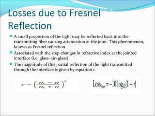
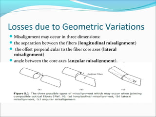
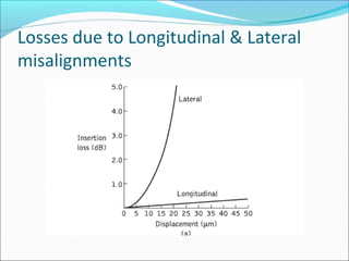
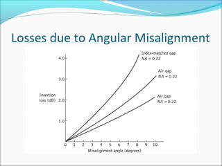
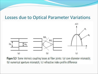
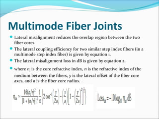
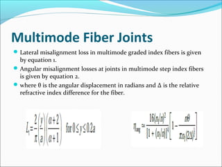
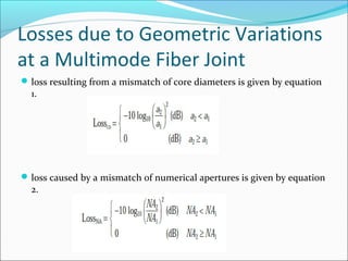
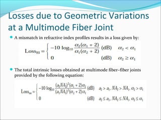
This document discusses optical losses associated with fiber optic joints. It describes losses from Fresnel reflection at the interface between fibers due to differences in refractive index. It also discusses losses from various types of geometric misalignments between fibers, including longitudinal offset, lateral offset, and angular misalignment. Finally, it examines losses from variations in optical parameters between fibers, such as core diameter, numerical aperture, and refractive index profile mismatches. Formulas are provided for calculating losses from many of these sources.
LEDs are of interest for fibre optics because of five inherent characteristics..
How it works?
Spectrum of an LED
Modulation of LED
LED Vs. Laser diode
disadvantages of LED
LEDs are of interest for fibre optics because of five inherent characteristics..
How it works?
Spectrum of an LED
Modulation of LED
LED Vs. Laser diode
disadvantages of LED
Unit II- TRANSMISSION CHARACTERISTIC OF OPTICAL FIBER tamil arasan
Attenuation - Absorption losses, Scattering losses, Bending Losses, Core and Cladding losses, Signal Distortion in Optical Wave guides-Information Capacity determination -Group Delay-Material Dispersion, Wave guide Dispersion, Signal distortion in SM fibers-Polarization Mode dispersion, Intermodal dispersion, -Design Optimization of SM fibers-RI profile and cut-off wavelength.
The attached narrated power point presentation attempts to explain the methods of computation of total power loss and system rise time in a fiber optic link. The material will be useful for KTU final year B Tech students who prepare for the subject EC 405, Optical Communications.
This narrated power point presentation attempts to examine the losses due to non-linear effects in optical fibers. The material will be useful for KTU final year B Tech students who prepare for the subject EC 405, Optical Communications.
Hello everyone. This is a short presentation on path loss and shadowing. I have not covered all the topics but a brief idea is given on path loss and wireless channel propagation models.
Hope you find it useful.
Thanks
The attached narrated power point presentation attempts to explain the working principle, types, classifications, merits, demerits, applications,safety and deployment issues related to Raman Amplifiers. The material will be useful for KTU final year B Tech students who prepare for the subject EC 405, Optical Communications.
Optical fiber communication Part 1 Optical Fiber FundamentalsMadhumita Tamhane
Optical fiber systems grew from combination of semiconductor technology, which provided necessary light sources and photodetectors and optical waveguide technology. It has significant inherent advantages over conventional copper systems- low transmission loss, wide BW, light weight and size, immunity to interferences, signal security to name a few. One principle characteristic of optical fiber is its attenuation as a function of wavelength. Hence it is operated in two major low attenuation wavelength windows 800-900nm and 1100-1600nm . Light travels inside optical fiber waveguide on principle of total internal reflection. Fiber is available as single mode and multiple mode, step index and graded index depending on applications and expenditures. Principle of fiber can be understood by ray theory or mode theory. ...
Analysis on The Impact of Reflectance in Optical Fiber Linksijtsrd
An optical fiber link is a part of an optic fiber communication system. Other components of the optic fiber link include the transmitter, connectors, and the receiver. The optical fiber could be single-mode (for long distance transmission) or multi-mode (for short distance transmission). This paper however, majors on the impact of reflectance in the single-mode optical fiber. Reflectance is a hidden threat that increases Bit Error Rate, BER, (rate at which errors occur in transmission system) and reduces system performance if not monitored or controlled. Optical Time Domain Reflectometer (OTDR) was used to measure the reflectance in single-mode fiber. Events measurements in OTDR heavily depend on good reflectance. The OTDR was able to establish the reflectance in every portion of the fiber under test. An average reflectance level of -14.9275 dB of 1550 nm signal over the span length of 20.422 km was achieved which is within the acceptable standard range. Hence, good quality performance transmissions can be achieved along these routes. J. Ilouno | M. Awoji | J. Sani"Analysis on The Impact of Reflectance in Optical Fiber Links" Published in International Journal of Trend in Scientific Research and Development (ijtsrd), ISSN: 2456-6470, Volume-2 | Issue-4 , June 2018, URL: http://www.ijtsrd.com/papers/ijtsrd14378.pdf http://www.ijtsrd.com/physics/other/14378/analysis-on-the-impact-of-reflectance-in-optical-fiber-links/j-ilouno
Signal Degradation In Optical Fiber
Losses in an optical fibre:-
The types of losses in a optical fibre are
Attenuation loss
Absorption
Scattering
Bending loss
Dispersion loss
Coupling loss
Bending losses of power in a single mode step index optical fiber due to macro bending has been
investigated for a wavelength of 1550nm. The effects of bending radius (4-15mm, with steps of 1mm), and
wrapping turn (up to 40 turns) on loss have been studied. Twisting the optical fiber and its influence on power
loss also has been investigated. Variations of macro bending loss with these two parameters have been
measured, loss with number of turns and radius of curvature have been measured.
This work founds that the Macro bending and wrapping turn loss increases as the bending radius and wrapping
turn increases.
Twenty Essential Knowledge of Optical Cable.pdfHYC Co., Ltd
An article about basic knowledge of optical fiber cable, including the wavelength, dispersion of optical fiber, insertion loss, return loss, fiber core diameter, types of optical fiber etc. Including What is the mode field diameter (MFD), What is Numerical Aperture (NA), What is the cutoff wavelength and so on.
Sachpazis:Terzaghi Bearing Capacity Estimation in simple terms with Calculati...Dr.Costas Sachpazis
Terzaghi's soil bearing capacity theory, developed by Karl Terzaghi, is a fundamental principle in geotechnical engineering used to determine the bearing capacity of shallow foundations. This theory provides a method to calculate the ultimate bearing capacity of soil, which is the maximum load per unit area that the soil can support without undergoing shear failure. The Calculation HTML Code included.
Industrial Training at Shahjalal Fertilizer Company Limited (SFCL)MdTanvirMahtab2
This presentation is about the working procedure of Shahjalal Fertilizer Company Limited (SFCL). A Govt. owned Company of Bangladesh Chemical Industries Corporation under Ministry of Industries.
NO1 Uk best vashikaran specialist in delhi vashikaran baba near me online vas...Amil Baba Dawood bangali
Contact with Dawood Bhai Just call on +92322-6382012 and we'll help you. We'll solve all your problems within 12 to 24 hours and with 101% guarantee and with astrology systematic. If you want to take any personal or professional advice then also you can call us on +92322-6382012 , ONLINE LOVE PROBLEM & Other all types of Daily Life Problem's.Then CALL or WHATSAPP us on +92322-6382012 and Get all these problems solutions here by Amil Baba DAWOOD BANGALI
#vashikaranspecialist #astrologer #palmistry #amliyaat #taweez #manpasandshadi #horoscope #spiritual #lovelife #lovespell #marriagespell#aamilbabainpakistan #amilbabainkarachi #powerfullblackmagicspell #kalajadumantarspecialist #realamilbaba #AmilbabainPakistan #astrologerincanada #astrologerindubai #lovespellsmaster #kalajaduspecialist #lovespellsthatwork #aamilbabainlahore#blackmagicformarriage #aamilbaba #kalajadu #kalailam #taweez #wazifaexpert #jadumantar #vashikaranspecialist #astrologer #palmistry #amliyaat #taweez #manpasandshadi #horoscope #spiritual #lovelife #lovespell #marriagespell#aamilbabainpakistan #amilbabainkarachi #powerfullblackmagicspell #kalajadumantarspecialist #realamilbaba #AmilbabainPakistan #astrologerincanada #astrologerindubai #lovespellsmaster #kalajaduspecialist #lovespellsthatwork #aamilbabainlahore #blackmagicforlove #blackmagicformarriage #aamilbaba #kalajadu #kalailam #taweez #wazifaexpert #jadumantar #vashikaranspecialist #astrologer #palmistry #amliyaat #taweez #manpasandshadi #horoscope #spiritual #lovelife #lovespell #marriagespell#aamilbabainpakistan #amilbabainkarachi #powerfullblackmagicspell #kalajadumantarspecialist #realamilbaba #AmilbabainPakistan #astrologerincanada #astrologerindubai #lovespellsmaster #kalajaduspecialist #lovespellsthatwork #aamilbabainlahore #Amilbabainuk #amilbabainspain #amilbabaindubai #Amilbabainnorway #amilbabainkrachi #amilbabainlahore #amilbabaingujranwalan #amilbabainislamabad
Welcome to WIPAC Monthly the magazine brought to you by the LinkedIn Group Water Industry Process Automation & Control.
In this month's edition, along with this month's industry news to celebrate the 13 years since the group was created we have articles including
A case study of the used of Advanced Process Control at the Wastewater Treatment works at Lleida in Spain
A look back on an article on smart wastewater networks in order to see how the industry has measured up in the interim around the adoption of Digital Transformation in the Water Industry.
About
Indigenized remote control interface card suitable for MAFI system CCR equipment. Compatible for IDM8000 CCR. Backplane mounted serial and TCP/Ethernet communication module for CCR remote access. IDM 8000 CCR remote control on serial and TCP protocol.
• Remote control: Parallel or serial interface.
• Compatible with MAFI CCR system.
• Compatible with IDM8000 CCR.
• Compatible with Backplane mount serial communication.
• Compatible with commercial and Defence aviation CCR system.
• Remote control system for accessing CCR and allied system over serial or TCP.
• Indigenized local Support/presence in India.
• Easy in configuration using DIP switches.
Technical Specifications
Indigenized remote control interface card suitable for MAFI system CCR equipment. Compatible for IDM8000 CCR. Backplane mounted serial and TCP/Ethernet communication module for CCR remote access. IDM 8000 CCR remote control on serial and TCP protocol.
Key Features
Indigenized remote control interface card suitable for MAFI system CCR equipment. Compatible for IDM8000 CCR. Backplane mounted serial and TCP/Ethernet communication module for CCR remote access. IDM 8000 CCR remote control on serial and TCP protocol.
• Remote control: Parallel or serial interface
• Compatible with MAFI CCR system
• Copatiable with IDM8000 CCR
• Compatible with Backplane mount serial communication.
• Compatible with commercial and Defence aviation CCR system.
• Remote control system for accessing CCR and allied system over serial or TCP.
• Indigenized local Support/presence in India.
Application
• Remote control: Parallel or serial interface.
• Compatible with MAFI CCR system.
• Compatible with IDM8000 CCR.
• Compatible with Backplane mount serial communication.
• Compatible with commercial and Defence aviation CCR system.
• Remote control system for accessing CCR and allied system over serial or TCP.
• Indigenized local Support/presence in India.
• Easy in configuration using DIP switches.
Saudi Arabia stands as a titan in the global energy landscape, renowned for its abundant oil and gas resources. It's the largest exporter of petroleum and holds some of the world's most significant reserves. Let's delve into the top 10 oil and gas projects shaping Saudi Arabia's energy future in 2024.
Overview of the fundamental roles in Hydropower generation and the components involved in wider Electrical Engineering.
This paper presents the design and construction of hydroelectric dams from the hydrologist’s survey of the valley before construction, all aspects and involved disciplines, fluid dynamics, structural engineering, generation and mains frequency regulation to the very transmission of power through the network in the United Kingdom.
Author: Robbie Edward Sayers
Collaborators and co editors: Charlie Sims and Connor Healey.
(C) 2024 Robbie E. Sayers
CFD Simulation of By-pass Flow in a HRSG module by R&R Consult.pptxR&R Consult
CFD analysis is incredibly effective at solving mysteries and improving the performance of complex systems!
Here's a great example: At a large natural gas-fired power plant, where they use waste heat to generate steam and energy, they were puzzled that their boiler wasn't producing as much steam as expected.
R&R and Tetra Engineering Group Inc. were asked to solve the issue with reduced steam production.
An inspection had shown that a significant amount of hot flue gas was bypassing the boiler tubes, where the heat was supposed to be transferred.
R&R Consult conducted a CFD analysis, which revealed that 6.3% of the flue gas was bypassing the boiler tubes without transferring heat. The analysis also showed that the flue gas was instead being directed along the sides of the boiler and between the modules that were supposed to capture the heat. This was the cause of the reduced performance.
Based on our results, Tetra Engineering installed covering plates to reduce the bypass flow. This improved the boiler's performance and increased electricity production.
It is always satisfying when we can help solve complex challenges like this. Do your systems also need a check-up or optimization? Give us a call!
Work done in cooperation with James Malloy and David Moelling from Tetra Engineering.
More examples of our work https://www.r-r-consult.dk/en/cases-en/
CFD Simulation of By-pass Flow in a HRSG module by R&R Consult.pptx
Fiber alignment and joint loss
1.
2. CONTENTS
Introduction
Losses due to Fresnel Reflection.
Losses due to Geometric and Optical Parameter
variations.
Multimode Fiber Joints.
Single Mode Fiber Joints.
3. INTRODUCTION
Fiber splices: These are semipermanent or permanent joints which find
major use in most optical fiber telecommunication systems (analogous to
electrical soldered joints).
Demountable fiber connectors or simple connectors: These are
removable
joints which allow easy, fast, manual coupling and uncoupling of fibers
(analogous to electrical plugs and sockets).
A crucial aspect of fiber jointing concerns the optical loss associated with the
connection.
A major consideration with all types of fiber–fiber connection is the optical
loss encountered at the interface.
4. Losses due to Fresnel
Reflection
A small proportion of the light may be reflected back into the
transmitting fiber causing attenuation at the joint. This phenomenon,
known as Fresnel reflection
Associated with the step changes in refractive index at the jointed
interface (i.e. glass–air–glass).
The magnitude of this partial reflection of the light transmitted
through the interface is given by equation 1.
5. Losses due to Fresnel
Reflection
The loss in decibels due to Fresnel reflection at a single interface is
given by equation 2.
Where n1 is the refractive index of the fiber core and n is the refractive
index of the medium between the two jointed fibers.
The effect of Fresnel reflection at a fiber–fiber connection can be
reduced by the use of an index-matching fluid between the gap.
6. Losses due to Geometric Variations
Misalignment may occur in three dimensions:
the separation between the fibers (longitudinal misalignment)
the offset perpendicular to the fiber core axes (lateral
misalignment)
angle between the core axes (angular misalignment).
9. Losses due to Optical Parameter Variations
Losses at joints may occur due to the following reasons:
variations in core and/or cladding diameters.
variations in numerical apertures and/or relative refractive index
differences.
variations in refractive index profiles.
fiber faults (core ellipticity, core concentricity, etc.).
11. Multimode Fiber Joints
Lateral misalignment reduces the overlap region between the two
fiber cores.
The lateral coupling efficiency for two similar step index fibers (in a
multimode step index fiber) is given by equation 1.
The lateral misalignment loss in dB is given by equation 2.
where n1 is the core refractive index, n is the refractive index of the
medium between the fibers, y is the lateral offset of the fiber core
axes, and a is the fiber core radius.
12. Multimode Fiber Joints
Lateral misalignment loss in multimode graded index fibers is given
by equation 1.
Angular misalignment losses at joints in multimode step index fibers
is given by equation 2.
where θ is the angular displacement in radians and Δ is the relative
refractive index difference for the fiber.
13. Losses due to Geometric Variations
at a Multimode Fiber Joint
loss resulting from a mismatch of core diameters is given by equation
1.
loss caused by a mismatch of numerical apertures is given by equation
2.
14. Losses due to Geometric Variations
at a Multimode Fiber Joint
A mismatch in refractive index profiles results in a loss given by:
The total intrinsic losses obtained at multimode fiber–fiber joints
provided by the following equation: