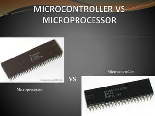
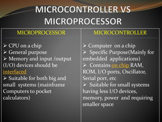
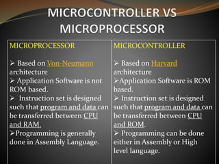
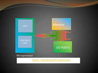
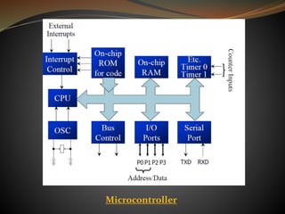
1. Calibrate the line sensor readings by taking multiple samples while turning left and right to determine the minimum and maximum values.
2. Continuously read the line sensor position and calculate the proportional, integral, and derivative terms based on the error from the center.
3. Determine the difference in motor powers needed to turn toward the center based on the PID values, without allowing negative powers.
4. Set the motor speeds based on the power difference to steer toward the center line.
This presentation gives an overview of the PIC micro-controllers. Additionally, it describes the advantages, disadvantages and applications of these micro-controllers. It also explains real-world projects that are possible using the PIC micro-controllers.
The document discusses the 8051 microcontroller. It provides three key criteria for choosing a microcontroller: 1) meeting computing needs efficiently and cost effectively, 2) availability of software development tools, and 3) reliable sources. It then describes the basic components and features of the 8051, including 4K bytes of ROM, 128 bytes of RAM, four 8-bit I/O ports, two timers/counters, a serial interface, and support for external memory. Finally, it explains the memory organization and allocation of the 8051, distinguishing program memory, data memory, and external RAM.
The document describes the 8051 microcontroller, its features which include 4 I/O ports, 2 timers, serial communication interface, and interrupts. It discusses the internal architecture such as memory organization, registers, and oscillator circuit. The document also provides details on the ports, timers, serial communication, and power modes of the 8051 microcontroller.
Presents features of ARM Processors, ARM architecture variants and Processor families. Further presents, ARM v4T architecture, ARM7-TDMI processor: Register organization, pipelining, modes, exception handling, bus architecture, debug architecture and interface signals.
In the project#1, IBM 130nm process is used to design and manual layout a 128 word SRAM, with word size 10bits. Cadence's Virtuoso is applied for layout editing, DRC and LVS running and circuit simulation.
The document discusses interfacing a stepper motor with an 8051 microcontroller. A stepper motor can divide a full rotation into discrete steps through energizing coils in different sequences. The stepper motor can be interfaced with an 8051 using an L293D motor driver connected to ports P1.0, P1.2, P1.3, and P1.4 of the 8051. Both full-step and half-step sequences are described for energizing the coils to precisely control the motor's position without feedback. Assembly and C code examples are provided to demonstrate clockwise and counterclockwise rotation of the stepper motor connected to the 8051.
The document provides an overview of microprocessors and microcontrollers. It discusses the history of microprocessors from early 4-bit processors to modern 64-bit processors. A microprocessor contains a central processing unit while a microcontroller contains additional components like memory and input/output interfaces integrated into a single chip. Microcontrollers require less external hardware than microprocessors. The document describes the basic architecture of microprocessors and microcontrollers including components like registers, buses, and memory. It compares the von Neumann and Harvard architectures. Interrupts and memory-mapped I/O are also discussed.
1. To make asynchronous serial communication using a microcontroller's USART, the transmitter must configure the baud rate generator and enable transmission by writing data to the transmit register, while the receiver must configure the baud rate generator and enable reception to read incoming data from the receive register.
2. Key steps include setting the SPBRG register and BRGH bit to determine the baud rate, enabling the serial port and transmission/reception, handling 9-bit data if needed, and checking status registers for transmission completion or errors.
3. Asynchronous serial communication allows microcontrollers to transmit data bit by bit over a single line using start and stop bits for synchronization instead of a separate clock line.
This document discusses pulse width modulation (PWM) and how it is implemented on the LPC2148 microcontroller. PWM is a technique for controlling the power delivered to a load by varying the duty cycle, or on-time, of a pulse signal while keeping frequency constant. The LPC2148 has a 32-bit timer/counter for PWM that can generate either single-edge or double-edge controlled PWM signals on multiple pins. It uses match registers to set the PWM period and pulse widths by controlling the rising and/or falling edges of the output pulses.
An LCD display is specifically designed to interface with microcontrollers and not standard ICs. It can display letters, symbols, and user-defined characters. Interfacing an LCD with an 8051 microcontroller involves understanding the LCD's pins and commands, and using C or assembly code to control write and read operations to the LCD. More details on interfacing LCDs with 8051 microcontrollers can be found on the listed websites.
The PIC 16F877A microcontroller uses a Harvard architecture with separate program and data buses. It has 8kB of flash memory, 368 bytes of RAM, and 256 bytes of EEPROM. It features five I/O ports, three timers, USART serial communication, and 15 interrupt sources. Instructions are in RISC format and execute in 4 machine cycles, with most instructions completing in one cycle.
The document describes the design of an 8-bit arithmetic logic unit (ALU) including a block diagram, flowchart, Verilog code, test bench, and simulation results. It also includes the synthesis report, device utilization summary, power and thermal analysis, and discusses future extensions such as parallel processing using pipelining.
A microcontroller is a computer system on a single chip that contains a processor core, memory, and programmable input/output peripherals. Microcontrollers are commonly used to control objects, processes, or events. They are often embedded in devices to control their functions. A microcontroller contains a CPU, RAM, ROM, flash memory, I/O ports, an ADC, and timers. Common microcontrollers include the Intel 8051, Atmel ATmega 16, and PIC microcontrollers. The microcontroller reads programmed instructions from flash memory and executes them via the CPU to control its I/O pins based on inputs.
This presentation discusses the Serial Communication features in 8051, the support for UART. It also discusses serial vs parallel communication, simplex, duplex and full-duplex modes, MAX232, RS232 standards
A microcontroller is a small computer on a single integrated circuit containing a processor core, memory, and programmable input/output peripherals. It is used in embedded systems to make decisions. The AVR ATmega8 is an 8-bit microcontroller based on Harvard architecture. It has 8KB of flash memory, 512B of EEPROM, and 1KB of SRAM. It contains peripherals like timers, PWM channels, ADC, and serial interfaces. The ATmega8 comes in PDIP and TQFP packages and uses three registers - DDRx, PORTx, and PINx - to communicate with its I/O ports.
This document provides an introduction to PIC microcontrollers. It discusses the architecture of PIC microcontrollers, including the 16C6x and 16C7x architectures. It describes the registers, memory, and instruction set of PIC microcontrollers. Some key points covered include the Harvard architecture, pipelining, addressing modes, arithmetic, logical, and conditional instructions. Peripherals like timers and interrupts are also mentioned.
The document is the user manual for the LPC17xx series of microcontrollers from NXP Semiconductors. It provides information about the ARM Cortex-M3 processor, memory, peripherals, and features of the chips. Revision 2 of the manual from August 19, 2010 includes various updates and corrections to the technical documentation.
8 Bit ALU is a combinational circuit which accepts two 8-bit numbers gives result.It is designed using the Verilog HDL code which is more useful for bachelor as well as masters engineering students.
The document discusses the 8051 microcontroller. It describes the basic components of the 8051 including 4K bytes of internal ROM, 128 bytes of internal RAM, four 8-bit I/O ports, two 16-bit timers/counters, and one serial interface. It provides a block diagram of the 8051 and discusses important pins such as the I/O ports, PSEN, ALE, EA, RXD, TXD, and XTAL1 and XTAL2. It also gives examples of how the 8051 is used in embedded systems and describes methods for connecting an external clock source to the 8051.
SYBSC IT SEM IV EMBEDDED SYSTEMS UNIT I Core of Embedded SystemsArti Parab Academics
The document discusses the core components of embedded systems. It states that embedded systems typically contain a central processing core that can be a microprocessor, microcontroller, digital signal processor (DSP), application-specific integrated circuit (ASIC), or programmable logic device. It also discusses other key components like sensors and actuators that interface with the outside world, communication interfaces, embedded firmware, and additional application-specific circuits.
The document discusses Dynamic Random Access Memory (DRAM). DRAM uses a capacitor and transistor to store each bit of data, which allows it to be implemented using less space than SRAM. However, DRAM is volatile and requires periodic refreshing to prevent data loss as the capacitor charge leaks over time. Common DRAM configurations include one transistor cells, three transistor cells, and four transistor cells. The document outlines the read and write operations for DRAM and how refreshing maintains the stored data.
The document discusses the 8051 microcontroller. It lists advantages of microcontroller-based systems such as lower cost, smaller size, and higher reliability compared to microprocessor-based systems. It describes some 8051 family members and compares their features such as ROM type, RAM size, and number of timers. It also discusses important components of the 8051 like ROM, RAM, I/O ports, timers, and serial port. The document provides block diagrams of the 8051 internal architecture and pinout. It describes the functions of various pins and registers.
This document provides an introduction and overview of microcontrollers. It begins by defining a microcontroller as a single-chip computer containing a CPU, RAM, ROM, I/O ports, and other peripherals. It then discusses the 8051 microcontroller in more detail, outlining its addressing modes, block diagram, operation, features, applications, and advantages over microprocessors. Finally, it provides a pin description and diagram of the 8051 microcontroller.
The microprocessor is the core of computer systems.
Nowadays many communication, digital entertainment, portable devices, are controlled by them.
A designer should know what types of components he needs, ways to reduce production costs and product reliable.
Analog to Digital Converter (ADC) is a device that converts an analog quantity (continuous voltage) to discrete digital values.
The PIC microcontroller can be used in various electronic devices like alarm systems, electronic gadgets and computer control systems.
The document discusses the features and architecture of the ARM9 processor. It describes the ARM9 as having a 5-stage pipeline, 32 registers, and support for both ARM and Thumb instruction sets. It supports DSP enhancements like single-cycle 32x16 multiplication and saturating arithmetic. The ARM9 powers applications in devices like smartphones, networking equipment, automotive systems, and embedded devices. The document then focuses on the specific ARM920T processor, which adds a 16KB cache and memory management unit to the ARM9 core.
The document discusses the Intel 8051 microcontroller family. It provides a brief history of the 8051, noting it was introduced in 1980 and had 128 bytes of internal RAM and 4Kbytes of ROM. It then lists several manufacturers of 8051 variants and their key features. The rest of the document goes into more detail about the hardware architecture of the 8051, including the pin descriptions and functions of the ports, timers, and serial interface.
The document provides an overview of the 8051 microcontroller, including its block diagram, pin descriptions, registers, memory mapping, stack, timers, and interrupts. It describes the CPU, RAM, ROM, I/O ports, timers, and interrupt control that are integrated into a single chip in the 8051 microcontroller. It also explains various registers related to timers and interrupts in the 8051.
The 8051 microcontroller has 4KB of ROM, 128KB of RAM, and 4 ports with 32 I/O lines. This configuration satisfies the needs of most programmers for developing automation devices. The 8051 has two types of memory - program memory (ROM) for permanently storing programs and data memory (RAM) for temporarily storing data and results. The 8051 has special function registers used for running and monitoring the microcontroller, including registers for timer control, interrupt control, and serial communication.
The document provides information about the 8051 microcontroller. It describes the basic components of a microcontroller including the CPU, memory, I/O ports, and timers. It explains the pin layout and functions of the 8051 microcontroller. Key components like registers, memory mapping, stack, and interrupts of the 8051 are summarized. Programming I/O ports and timers is also covered at a high level.
This document provides information about the features and architecture of the 8051 microcontroller. It describes the 8-bit CPU, 64K program memory, 64K data memory, 4K on-chip program memory, 128 bytes of on-chip data RAM, 32 I/O lines, two timers, UART serial communication, interrupt structure, and on-chip oscillator. It also covers the pin descriptions, registers, memory mapping, stack, I/O port programming, timers, and interrupts of the 8051. Finally, it discusses the instruction set groups for arithmetic, logical, data transfer, boolean, and program branching operations.
The document discusses the Microcontroller 8051. It provides a block diagram and pin description of the 8051. It describes the registers, memory mapping, stack, I/O ports, timers and interrupts of the 8051 microcontroller. It compares microprocessors and microcontrollers, discussing the differences in hardware structure and applications.
An embedded system is a special-purpose computer system designed to perform one or a few dedicated functions, often with real-time computing constraints. Embedded systems are present in many devices such as household appliances, vehicles, medical equipment, smartphones, and more. They typically use microcontrollers or microprocessors to monitor and control embedded hardware components. Key components of embedded systems include a CPU, memory, I/O ports, and timers/counters. Microcontrollers integrate most of these components onto a single chip, while microprocessors require external components. Embedded systems use various addressing modes and have inputs like interrupts and timers that allow them to interact with the external environment. Common applications areas of embedded systems include consumer electronics, industrial automation, automotive systems,
The document discusses the 8051 microcontroller, including its features, applications, and programming. It provides an overview of the 8051 architecture, describing its registers, memory mapping, I/O ports, timers, and interrupts. It also discusses how the 8051 is commonly used in applications like home appliances, industrial equipment, and toys.
The document discusses the 8051 microcontroller. It begins with an introduction and table of contents. It then provides details about the 8051 including its block diagram, pin descriptions and functions, memory mapping, registers, stack, I/O port programming, timers, and interrupts.
This document discusses an embedded systems presentation submitted by Amandeep Singh. It provides definitions and examples of embedded systems, noting they are designed for specific applications like industrial machines, medical equipment, and toys. It also summarizes key aspects of embedded system components like microcontrollers, addressing modes, and applications. Recent examples highlighted are devices that aid communication for the deaf, integrate weighing and dimension measuring, and allow adjustable cushioning in smart shoes.
Microcontroller (8051) by K. Vijay KumarVijay Kumar
The document provides an overview of microprocessors and microcontrollers. It discusses why they are needed in modern devices and some key components like the CPU, memory, I/O ports, and timers. The document then compares microprocessors and microcontrollers, noting that microcontrollers have these components integrated onto a single chip, making them well-suited for applications where cost, power and space are priorities. It also provides details on the 8051 microcontroller, including its memory architecture, I/O ports, and special function registers.
Presentation On: "Micro-controller 8051 & Embedded System"surabhii007
The presentation is dealing with majors about 'An Embedded System' along with 'Micro-controller' with it's base peripherals & parameters.
Hope It'll be helpfull!
The document discusses the 8051 microcontroller. It begins by explaining why we need to learn about microprocessors and microcontrollers, noting that many modern devices are controlled by them. It then covers the basic components of a microprocessor/controller including the CPU, I/O, memory, timers, and interrupts. The rest of the document provides details on the 8051 microcontroller, including its architecture, memory structure, registers, ports and other features. It compares microprocessors and microcontrollers, and discusses how to choose between different microcontroller options for embedded systems.
This PPT covers some important points of 8051 microcontroller like Applications, block diagram, Architecture, comparison between microprocessor and microcontroller, Pin diagram, RAM memory space allocation, register banks, Instruction set, Addresing modes, serial communication, baud rate, machine cycle, serial interface with PC, Introduction to Timers/Counters etc....
The document discusses embedded systems and microcontrollers. It provides information on what embedded systems are, examples of where they are used, components of embedded systems like microprocessors and microcontrollers, differences between microprocessors and microcontrollers, features of the Intel 8051 microcontroller and its applications in embedded systems. It also discusses addressing modes, timers, interrupts and embedded operating systems.
8051 microcontroller training (2) (sahil gupta 9068557926)Sahil Gupta
The document discusses microprocessors and microcontrollers. It begins by explaining that microprocessors are the core of modern computer systems and devices, and that they control communication, entertainment, and portable devices. It then contrasts microprocessors and microcontrollers, noting that microprocessors have external memory and I/O components while microcontrollers have these components integrated on a single chip. The document also provides details on the 8051 microcontroller, including its architecture, ports, memory organization, and interrupts.
The document describes the architecture and components of an 8051 microcontroller. It includes details about the CPU registers like the accumulator, program status word, stack pointer, and timers. It describes the ports, interrupts, and memory organization. The special function registers control functions like timers, serial communication, and interrupts. The timers can be configured in different modes to generate time delays or count events. External memory can be accessed using address and data lines connected to the ports.
The document discusses microprocessors and microcontrollers. It describes how microprocessors have external RAM, ROM, and I/O ports, while microcontrollers have RAM, ROM, I/O ports, and other components integrated into a single chip. The 8051 microcontroller is presented as a common example that has on-chip memory and I/O in addition to a CPU. Key features of the 8051 such as its memory organization, registers, addressing modes, and instruction set are outlined.
This document discusses seven segment displays and how to interface them with microcontrollers. A seven segment display uses 7 LED segments (a, b, c, d, e, f, g) plus a decimal point to display numbers from 0 to 9. There are two types: common cathode, where the cathodes are connected and the anodes are individual; and common anode, where the anodes are connected and the cathodes are individual. When interfacing with a microcontroller like the 8051, common cathode displays use logic high outputs while common anode uses logic low outputs to light the correct segments to display the desired number.
This document discusses several topics related to digital logic and programming languages:
1) It covers basic concepts of digital logic including number systems, logic gates, memory devices, and binary to hexadecimal conversion.
2) It also discusses high level, low level, and machine level programming languages as well as C programming constructs such as header files, if/else statements, loops, functions, and more.
3) Finally, it provides examples of coding in C including programs using if/else statements, while loops, for loops, and functions.
The document summarizes information about liquid crystal displays (LCDs), including:
- LCDs are replacing LED displays due to declining prices, ability to display text/graphics, and ease of programming text/graphics.
- It describes the pin connections and functions of an LCD, including power supply pins, data/command selection pins, data bus pins, and enable pin.
- It provides notes on programming an LCD, including using the busy flag pin to check if the LCD is busy before writing data.
Data Mining: Human and Wildlife conflict of CNPKshitij Wagle
This document summarizes a research presentation on predicting human-wildlife conflict in Chitwan National Park using data mining. It introduces the topic, discusses key aspects like conflict origins, outcomes, and the K-Modes clustering methodology used. The results show that conflict is most common in winter/spring, with elephants destroying crops randomly and tigers/leopards attacking livestock in spring. Rhinos attack humans and crops in winter. The research was limited by the compensation scheme and lack of temperature data, and could be enhanced by studying other areas and predicting species mobility.
This document provides an introduction to ASP.NET, describing it as a server-side scripting technology developed by Microsoft that allows for creating dynamic and interactive web pages. It notes that ASP.NET pages have a .aspx extension and uses tags like <asp:TextBox>. The document also gives a brief overview of how ASP.NET works, executing server-side scripts to generate HTML returned to browsers, and highlights some advantages of ASP.NET like its powerful IDE and use of server controls.
Wordpress vs Google Blogger/ WampserverKshitij Wagle
This slide helps you to understand about wampserver and basic idea about what is difference between wordpress and blogger along with their functionality.
Software Engineering and Project Management - Introduction, Modeling Concepts...Prakhyath Rai
Introduction, Modeling Concepts and Class Modeling: What is Object orientation? What is OO development? OO Themes; Evidence for usefulness of OO development; OO modeling history. Modeling
as Design technique: Modeling, abstraction, The Three models. Class Modeling: Object and Class Concept, Link and associations concepts, Generalization and Inheritance, A sample class model, Navigation of class models, and UML diagrams
Building the Analysis Models: Requirement Analysis, Analysis Model Approaches, Data modeling Concepts, Object Oriented Analysis, Scenario-Based Modeling, Flow-Oriented Modeling, class Based Modeling, Creating a Behavioral Model.
Introduction- e - waste – definition - sources of e-waste– hazardous substances in e-waste - effects of e-waste on environment and human health- need for e-waste management– e-waste handling rules - waste minimization techniques for managing e-waste – recycling of e-waste - disposal treatment methods of e- waste – mechanism of extraction of precious metal from leaching solution-global Scenario of E-waste – E-waste in India- case studies.
Electric vehicle and photovoltaic advanced roles in enhancing the financial p...IJECEIAES
Climate change's impact on the planet forced the United Nations and governments to promote green energies and electric transportation. The deployments of photovoltaic (PV) and electric vehicle (EV) systems gained stronger momentum due to their numerous advantages over fossil fuel types. The advantages go beyond sustainability to reach financial support and stability. The work in this paper introduces the hybrid system between PV and EV to support industrial and commercial plants. This paper covers the theoretical framework of the proposed hybrid system including the required equation to complete the cost analysis when PV and EV are present. In addition, the proposed design diagram which sets the priorities and requirements of the system is presented. The proposed approach allows setup to advance their power stability, especially during power outages. The presented information supports researchers and plant owners to complete the necessary analysis while promoting the deployment of clean energy. The result of a case study that represents a dairy milk farmer supports the theoretical works and highlights its advanced benefits to existing plants. The short return on investment of the proposed approach supports the paper's novelty approach for the sustainable electrical system. In addition, the proposed system allows for an isolated power setup without the need for a transmission line which enhances the safety of the electrical network
Build the Next Generation of Apps with the Einstein 1 Platform.
Rejoignez Philippe Ozil pour une session de workshops qui vous guidera à travers les détails de la plateforme Einstein 1, l'importance des données pour la création d'applications d'intelligence artificielle et les différents outils et technologies que Salesforce propose pour vous apporter tous les bénéfices de l'IA.
DEEP LEARNING FOR SMART GRID INTRUSION DETECTION: A HYBRID CNN-LSTM-BASED MODELijaia
As digital technology becomes more deeply embedded in power systems, protecting the communication
networks of Smart Grids (SG) has emerged as a critical concern. Distributed Network Protocol 3 (DNP3)
represents a multi-tiered application layer protocol extensively utilized in Supervisory Control and Data
Acquisition (SCADA)-based smart grids to facilitate real-time data gathering and control functionalities.
Robust Intrusion Detection Systems (IDS) are necessary for early threat detection and mitigation because
of the interconnection of these networks, which makes them vulnerable to a variety of cyberattacks. To
solve this issue, this paper develops a hybrid Deep Learning (DL) model specifically designed for intrusion
detection in smart grids. The proposed approach is a combination of the Convolutional Neural Network
(CNN) and the Long-Short-Term Memory algorithms (LSTM). We employed a recent intrusion detection
dataset (DNP3), which focuses on unauthorized commands and Denial of Service (DoS) cyberattacks, to
train and test our model. The results of our experiments show that our CNN-LSTM method is much better
at finding smart grid intrusions than other deep learning algorithms used for classification. In addition,
our proposed approach improves accuracy, precision, recall, and F1 score, achieving a high detection
accuracy rate of 99.50%.
Null Bangalore | Pentesters Approach to AWS IAMDivyanshu
#Abstract:
- Learn more about the real-world methods for auditing AWS IAM (Identity and Access Management) as a pentester. So let us proceed with a brief discussion of IAM as well as some typical misconfigurations and their potential exploits in order to reinforce the understanding of IAM security best practices.
- Gain actionable insights into AWS IAM policies and roles, using hands on approach.
#Prerequisites:
- Basic understanding of AWS services and architecture
- Familiarity with cloud security concepts
- Experience using the AWS Management Console or AWS CLI.
- For hands on lab create account on [killercoda.com](https://killercoda.com/cloudsecurity-scenario/)
# Scenario Covered:
- Basics of IAM in AWS
- Implementing IAM Policies with Least Privilege to Manage S3 Bucket
- Objective: Create an S3 bucket with least privilege IAM policy and validate access.
- Steps:
- Create S3 bucket.
- Attach least privilege policy to IAM user.
- Validate access.
- Exploiting IAM PassRole Misconfiguration
-Allows a user to pass a specific IAM role to an AWS service (ec2), typically used for service access delegation. Then exploit PassRole Misconfiguration granting unauthorized access to sensitive resources.
- Objective: Demonstrate how a PassRole misconfiguration can grant unauthorized access.
- Steps:
- Allow user to pass IAM role to EC2.
- Exploit misconfiguration for unauthorized access.
- Access sensitive resources.
- Exploiting IAM AssumeRole Misconfiguration with Overly Permissive Role
- An overly permissive IAM role configuration can lead to privilege escalation by creating a role with administrative privileges and allow a user to assume this role.
- Objective: Show how overly permissive IAM roles can lead to privilege escalation.
- Steps:
- Create role with administrative privileges.
- Allow user to assume the role.
- Perform administrative actions.
- Differentiation between PassRole vs AssumeRole
Try at [killercoda.com](https://killercoda.com/cloudsecurity-scenario/)
Design and optimization of ion propulsion dronebjmsejournal
Electric propulsion technology is widely used in many kinds of vehicles in recent years, and aircrafts are no exception. Technically, UAVs are electrically propelled but tend to produce a significant amount of noise and vibrations. Ion propulsion technology for drones is a potential solution to this problem. Ion propulsion technology is proven to be feasible in the earth’s atmosphere. The study presented in this article shows the design of EHD thrusters and power supply for ion propulsion drones along with performance optimization of high-voltage power supply for endurance in earth’s atmosphere.
Advanced control scheme of doubly fed induction generator for wind turbine us...IJECEIAES
This paper describes a speed control device for generating electrical energy on an electricity network based on the doubly fed induction generator (DFIG) used for wind power conversion systems. At first, a double-fed induction generator model was constructed. A control law is formulated to govern the flow of energy between the stator of a DFIG and the energy network using three types of controllers: proportional integral (PI), sliding mode controller (SMC) and second order sliding mode controller (SOSMC). Their different results in terms of power reference tracking, reaction to unexpected speed fluctuations, sensitivity to perturbations, and resilience against machine parameter alterations are compared. MATLAB/Simulink was used to conduct the simulations for the preceding study. Multiple simulations have shown very satisfying results, and the investigations demonstrate the efficacy and power-enhancing capabilities of the suggested control system.
2. MICROPROCESSOR
CPU on a chip
General purpose
Memory and input /output
(I/O) devices should be
interfaced
Suitable for both big and
small systems (mainframe
Computers to pocket
calculators)
MICROCONTROLLER
Computer on a chip
Specific Purpose(Mainly for
embedded applications)
Contains on chip RAM,
ROM, I/O ports, Oscillator,
Serial port, etc
Suitable for small systems
having less I/O devices,
memory, power and requiring
smaller space
3. MICROPROCESSOR
Based on Von-Neumann
architecture
Application Software is not
ROM based.
Instruction set is designed
such that program and data can
be transferred between CPU
and RAM.
Programming is generally
done in Assembly Language.
MICROCONTROLLER
Based on Harvard
architecture
Application Software is ROM
based.
Instruction set is designed
such that program and data can
be transferred between CPU
and ROM.
Programming can be done
either in Assembly or High
level language.
4. Household Items
Toys, Cameras, Video Recorders, CD players, TVs,
Microwave Ovens, Washing Machines, Vacuum Cleaners,
Home Security Systems, etc.
8. Intel introduced 8051, referred as MCS-51, in 1981.
Due to the flexibility and versatility of 8051 family microcontrollers,
they are quite popular till now.
Feature/Chip 8051 8031 8052 AT89S52
ROM 4K 0K 8K Flash 4K
RAM 128 bytes 128 bytes 256 bytes 128 bytes
I/O Pins 32 32 32 32
Serial I/O 1 1 1 1
Timer 2 2 3 2
Interrupt
Source
6 6 8 6
Large block of data is erased and written in Flash EPROM while only byte by byte
erasing and writing is available in EEPROM
INTRODUCTION TO MICROCONTROLLER
9. On-chip Oscillator
On-chip RAM of limited size
On-chip ROM of limited size
On-chip I/O ports
Built in full duplex serial port
On-chip timer/counter
Bus control to interface external RAM and ROM(64
kb each)
Large Set of Special Purpose registers
Boolean Processing Capacity (Bit addressable)
Multiple Functionality of Pins
Key Features of 8051 microcontrollers
12. VCC (PIN 40) :
Supply voltage (+5V) is provided to chip
GND(PIN 20):
Ground or Common terminal of supply
XTAL1 (PIN 19) & XTAL2 (PIN 18):
As discussed earlier 8051 microcontroller possess on-chip
Oscillator. It can generate frequency of 1.24 MHz to 12 MHz
Generally a quartz crystal of 12 MHz frequency is connected
to the pins 18 and 19.
The actual frequency produced is 11.0592 MHz
PIN DESCRIPTION OF 8051 MICROCONTROLLER
13. Also two capacitors of around 30 pF are connected as shown in figure.
The quartz crystal and capacitors help to produce clock pulse of exact
frequency not some harmonic frequency.
If a frequency source other than a crystal
oscillator is used , such as a TTL Oscillator,
it will be connected to XTAL1 and XTAL2 is
left unconnected.
PIN DESCRIPTION OF 8051 MICROCONTROLLER
14. RST(PIN 9):
RST stands for system RESET and is active high signal.(Normally low)
The Microcontroller is reset by holding RST high for at least two
machine cycles and then returning it low.
The execution of the program stops and begins at the first location in
program memory (ROM) on reset.
Need of RST circuitry
oWhen the supply is just turned on.
(Transient Effect)
oAs backup power source.
15. __
EA (PIN 31):
EA stands for “External Access” and is an input signal which is
either connected to VCC or GND.
If the program is stored in on-chip ROM then, EA is
connected to VCC.
If the program is stored in external ROM then, EA is
connected to GND.
16. _____
PSEN (PIN 29):
It stands for “Program Store Enable”.
It is an output pin and it is connected to the OE(Output
Enable) pin of the ROM.
It distinguish between program memory and data Memory.
17. ALE (PIN 30):
ALE stands for “Address Latch Enable” and is an active high
output pin.
Port o has got three functionality viz. I/O port, Address
and Data.
ALE indicates if P0 has address or data
• When ALE=0, it provides data D0-D7
•When ALE=1, it has address A0-A7
18. PORT P0 (PIN 39 TO 32)
Port P0 has got three functionalities.(I/O port, lower order
address(A0 to A7) and data (D0 to D7).
It can be used for input or output , each pin must be connected
externally to a 10K ohm pull-up resistor.
ALE indicates if P0 has address or data
When ALE=0, it provides data D0-D7
When ALE=1, it has address A0-A7
19. PORT P1 (PIN 1 TO 8)
Port P1 is simple I/O port .
Internal pull up resistor is provided.
PORT P2(PIN 21 TO 28)
Port P2 has dual functionality.( I/o port and higher order address(A8 to
A15).
Port 2 must be used along with P0 to provide the 16-bit address for the
external memory.
Internal pull up resistor is provided.
20. PORT P3 (PIN 10 TO 17)
Port 3 can be used as input or output.
Port 3 does not need any pull-up resistors.
Port 3 has the additional function of providing some extremely
important signals.