Download to read offline

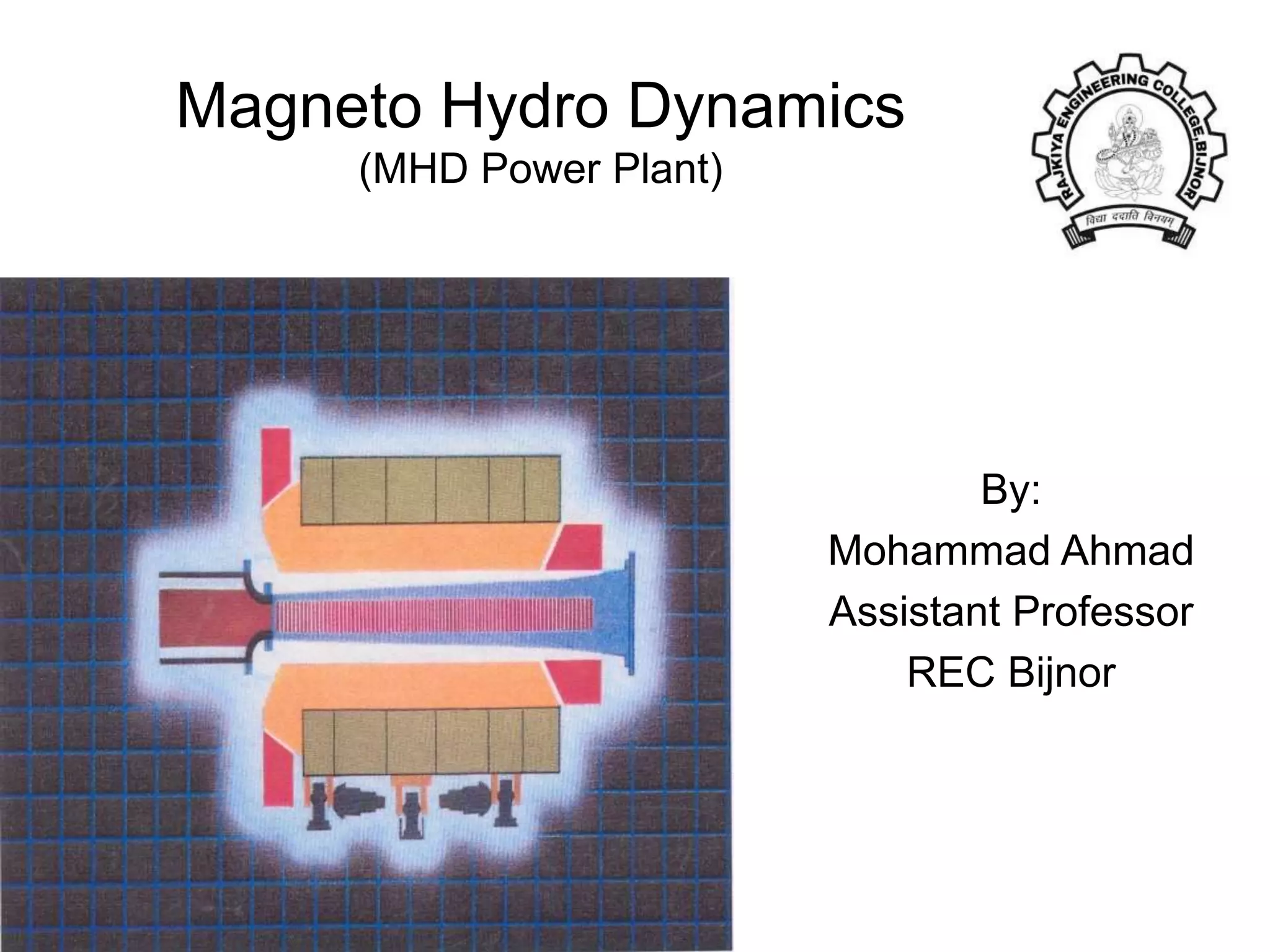
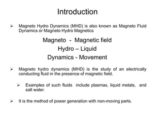
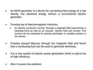
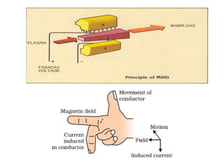
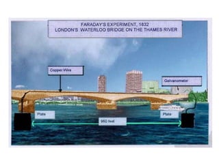

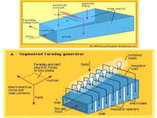

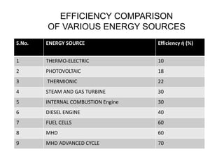

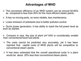
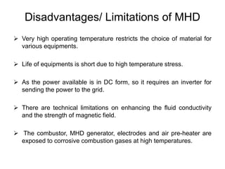


The document discusses Magneto Hydro Dynamics (MHD) power generation. MHD utilizes a conducting fluid, such as plasma or liquid metals, moving through a magnetic field to generate electricity. It has no moving parts and higher efficiency than conventional steam plants. The document describes Faraday's experiments, open and closed MHD systems, types using seeded inert gases or liquid metals, applications, existing MHD facilities including ones in India, advantages like higher efficiency and compact size, and disadvantages like requiring very high operating temperatures.