Downloaded 652 times


This document discusses magneto hydrodynamic (MHD) power generation. It begins with an introduction to MHD, which involves studying electrically conducting fluids in magnetic fields. An MHD generator directly converts heat energy to electrical energy without a conventional generator. The principle is that an induced voltage and current are generated when an ionized gas flows at high velocity through a magnetic field. The document describes open-cycle and closed-cycle MHD systems, advantages including higher efficiency and smaller size compared to conventional power plants, and challenges needing further development.
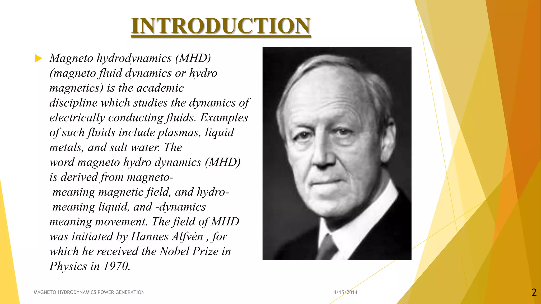
Introduction to Magneto Hydrodynamics (MHD), its significance, and MHD generators for efficient, low pollution power generation.
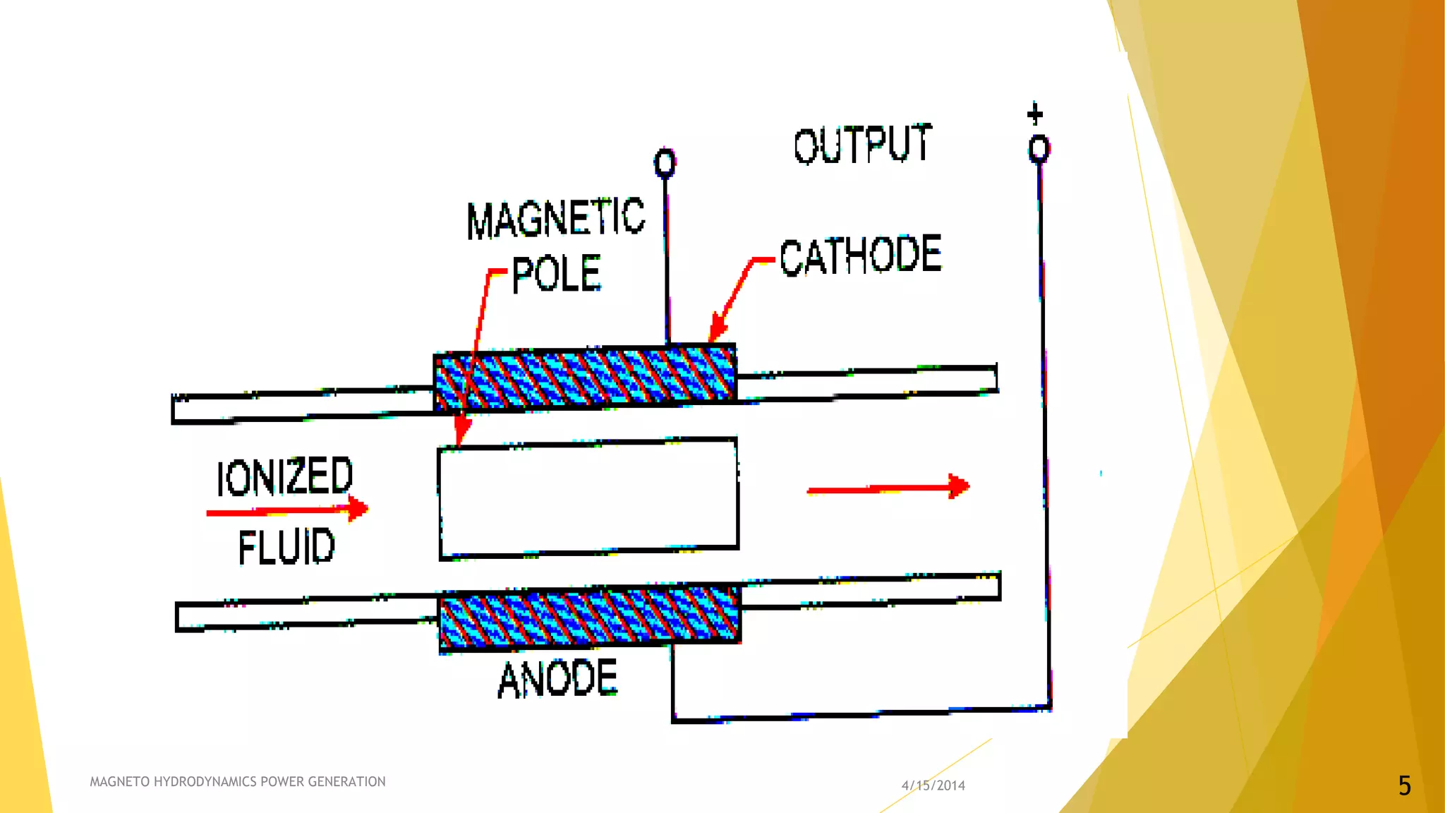
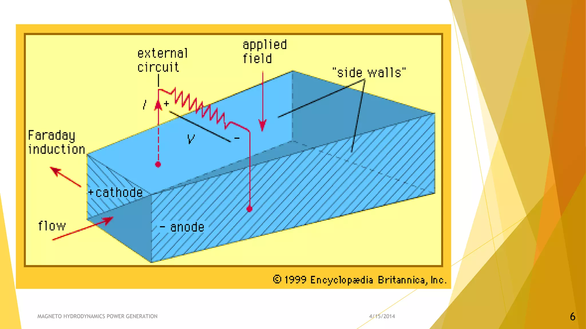
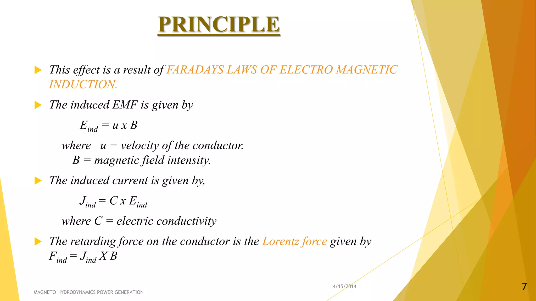
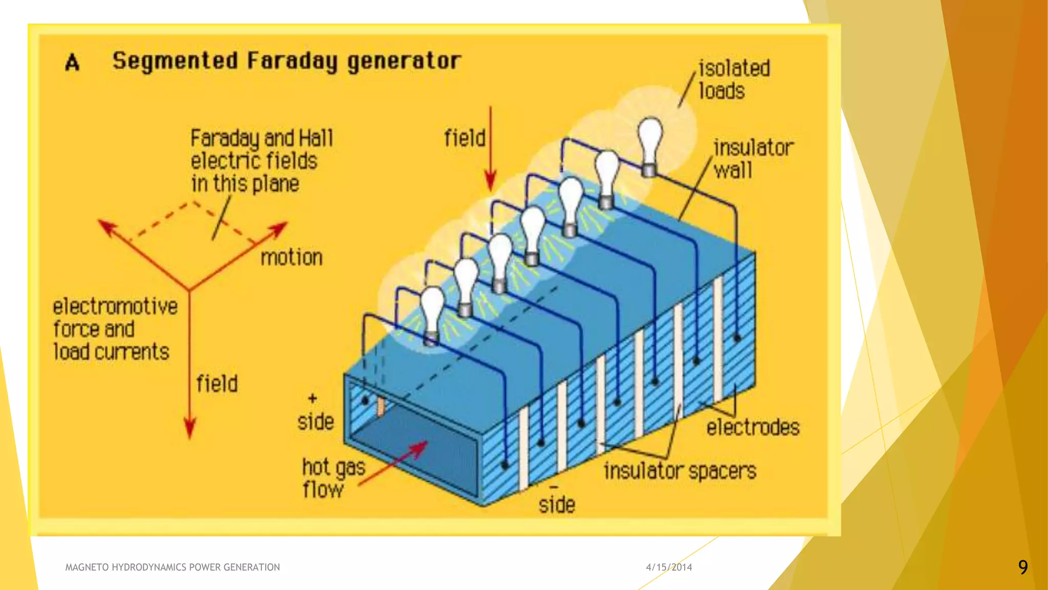
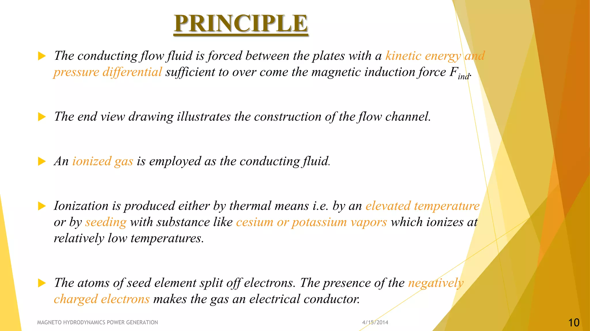
Explains the principle of MHD generation involving electric conductors in magnetic fields, including Faraday's laws and ionization.
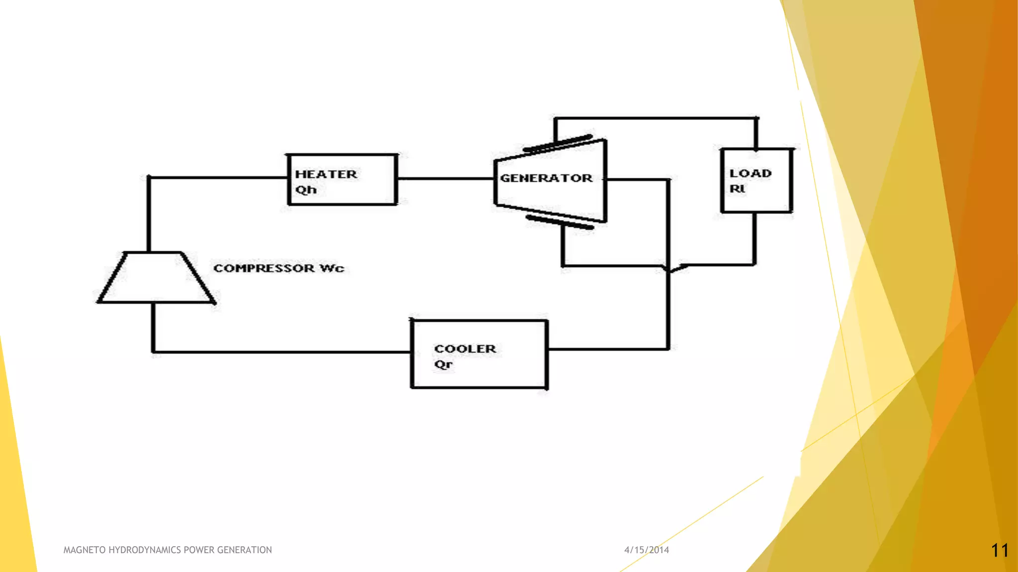
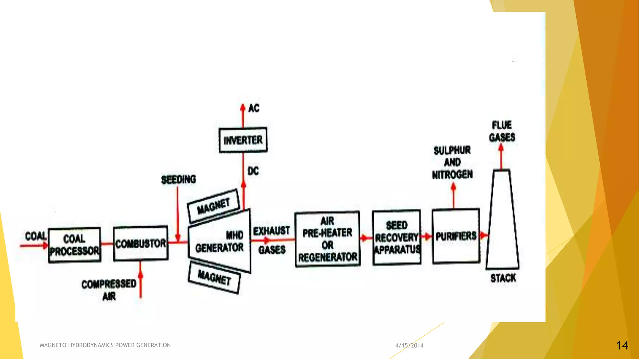
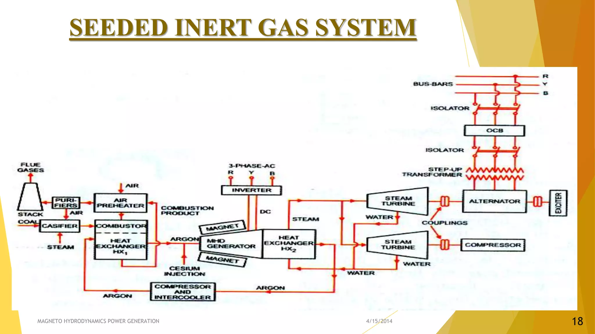
Classification of MHD systems into open and closed cycle systems, detailing methodology for energy conversion.Description of open cycle systems, fuel sources, temperature requirements, and MHD generator functions.
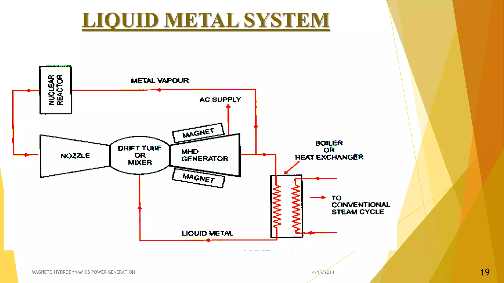
Overview of closed cycle systems, types of working fluids used, including liquid metals and inert gases.
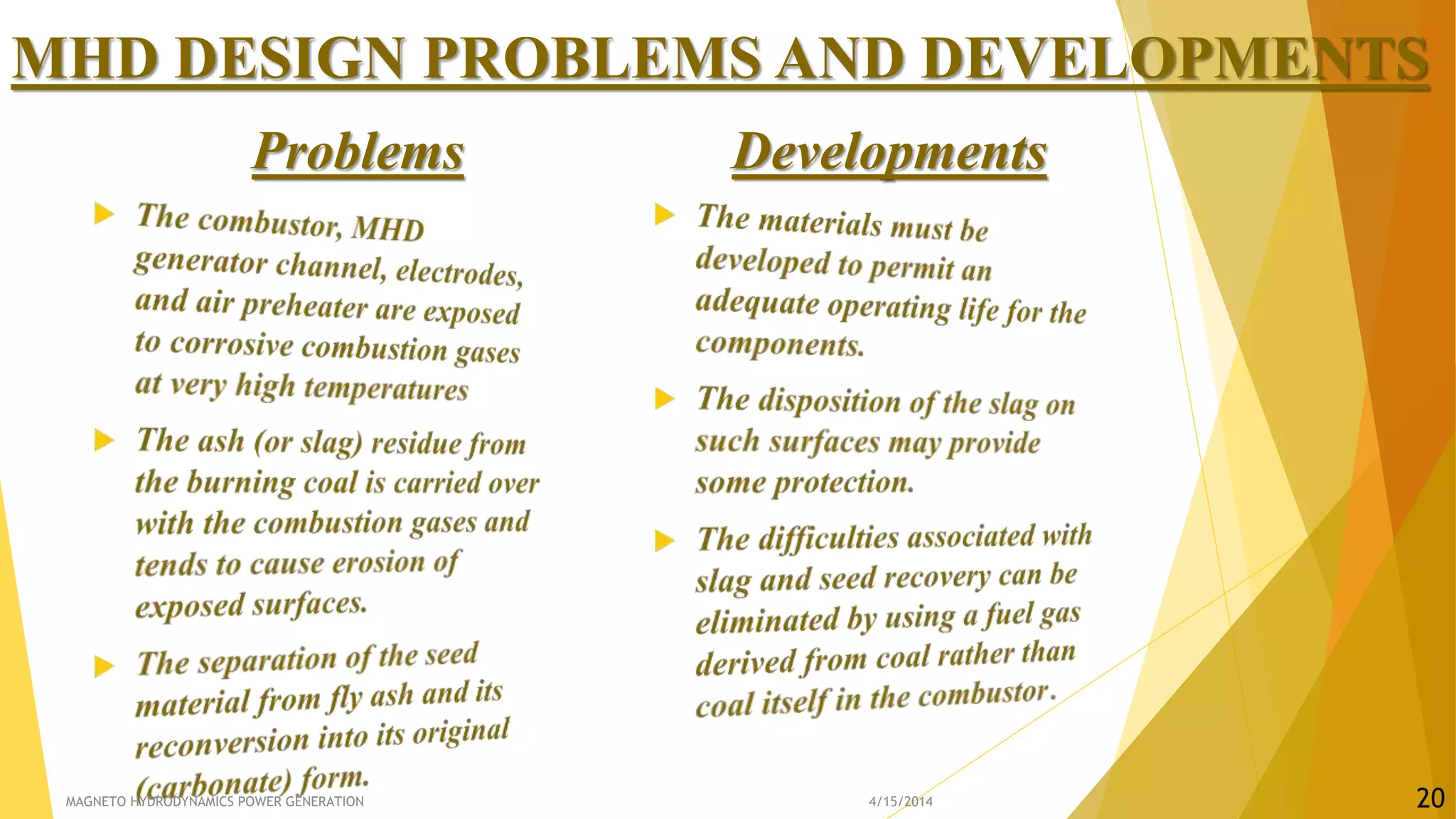
Summary of MHD design problems and developments.
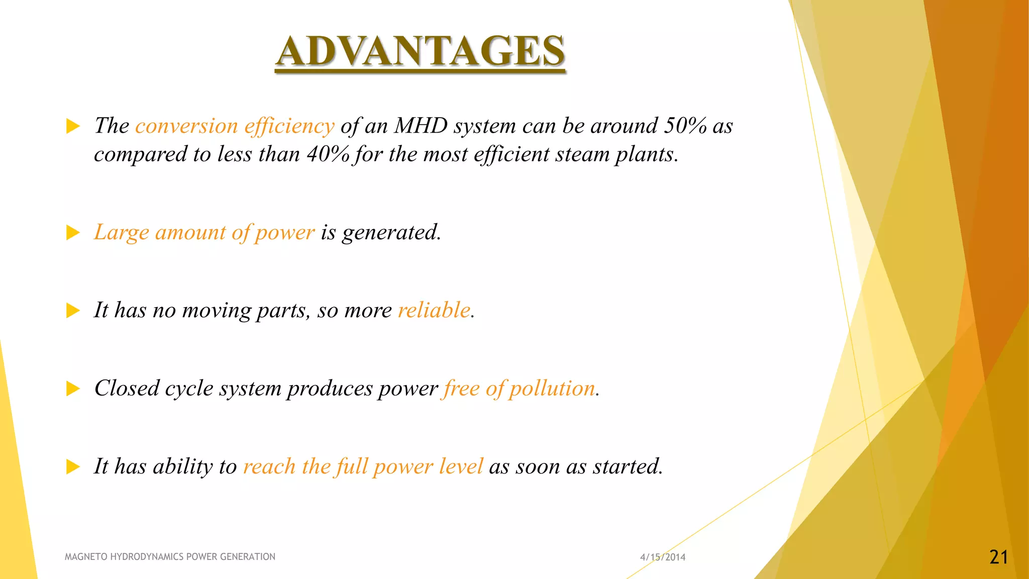
Advantages of MHD systems include high efficiency, reliability, low pollution, reduced operational costs, and better fuel utilization.


