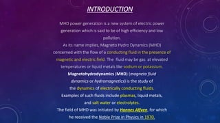
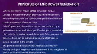
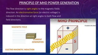
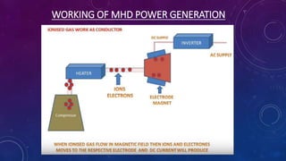
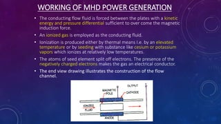
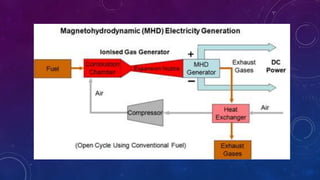
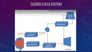
A
PRESENTATION
ON
MAGNETO HYDRO DYNAMIC POWER
GENERATION (MHD POWER GENERATION)
A SEMINAR IN PARTIAL FULFILLMENT OF THE REQUIREMENT FOR THE AWARD OF THE DEGREE OF
BACHELOR OF TECHNOLOGY
IN
ELECTRICAL ENGINEERING
FROM
BABU BANARASI DAS NATIONAL INSTITUTE OF TECHNOLOGY & MANAGEMENT (LUCKNOW)
AFFILIATED WITH APJ AKTU
SUBMITTED BY SUBMITTED TO
MRINALINI SRIVASTAVARISHASBH DEV SINGH
CONTENTS
o INTRODUCTION
o PRINCIPLE
o WORKING
o VARIOUS SYSTEM
o ADVANTAGES
o LIMITATIONS
o PROBLEMS ENCOUNTERED
o CONCLUSION
INTRODUCTION
MHD power generation is a new system of electric power
generation which is said to be of high efficiency and low
pollution.
As its name implies, Magneto Hydro Dynamics (MHD)
concerned with the flow of a conducting fluid in the presence of
magnetic and electric field. The fluid may be gas at elevated
temperatures or liquid metals like sodium or potassium.
Magnetohydrodynamics (MHD) (magneto fluid
dynamics or hydromagnetics) is the study of
the dynamics of electrically conducting fluids.
Examples of such fluids include plasmas, liquid metals,
and salt water or electrolytes.
The field of MHD was initiated by Hannes Alfven, for which
he received the Noble Prize in Physics in 1970.
PRINCIPLES OF MHD POWER GENERATION
When an conductor moves across a magnetic field, a
voltage is induced in it which produces an electric current.
This is the principle of the conventional generator where the
conductors consist of copper strips.
In MHD generator, the solid conductors are replaced by a
gaseous conductor, an ionized gas. If such a gas is passed at a
high velocity through a powerful magnetic field, a current is
generated and can be extracted by placing electrodes in
suitable position in the stream.
The principle can be explained as follows: An conductor
moving through a magnetic field experiences a retarding force as
well as an induced electric field and current
PRINCIPLE OF MHD POWER GENERATION
The flow direction is right angles to the magnetic fields
direction. An electromotive force (or electric voltage) is
induced in the direction at right angles to both flow and
field directions.
WORKING OF MHD POWER GENERATION
• The conducting flow fluid is forced between the plates with a kinetic
energy and pressure differential sufficient to over come the magnetic
induction force.
• An ionized gas is employed as the conducting fluid.
• Ionization is produced either by thermal means I.e. by an elevated
temperature or by seeding with substance like cesium or potassium
vapors which ionizes at relatively low temperatures.
• The atoms of seed element split off electrons. The presence of the
negatively charged electrons makes the gas an electrical conductor.
• The end view drawing illustrates the construction of the flow
channel.
VARIOUS MHD SYSTEMS
The MHD systems are broadly classified into two types.
• OPEN CYCLE SYSTEM
• CLOSED CYCLE SYSTEM
• Seeded inert gas system
• Liquid metal system
OPEN CYCLE SYSTEM
• The fuel used maybe oil through an oil tank or gasified coal
through a coal gasification plant.
• The fuel (coal, oil or natural gas) is burnt in the combustor or
combustion chamber.
• The hot gases from combustor is then seeded with a small
amount of ionized alkali metal (cesium or potassium) to
increase the electrical conductivity of the gas.
• The seed material, generally potassium carbonate is injected
into the combustion chamber, the potassium is then ionized by
the hot combustion gases at temperature of roughly 2300’ c to
2700’c.
OPEN CYCLE SYSTEM
• To attain such high temperatures, the compressed air is
used to burn the coal in the combustion chamber, must be
adequate to at least 1100’c.
• The hot pressurized working fluid living in the combustor
flows through a convergent divergent nozzle. In passing
through the nozzle, the random motion energy of the
molecules in the hot gas is largely converted into directed,
mass of energy. Thus , the gas emerges from the nozzle and
enters the MHD generator unit at a high velocity.
CLOSED CYCLE SYSTEM
• Two general types of closed cycle MHD generators are
being investigated.
• Seeded Inert Gas System
• Liquid Metal System
CLOSED CYCLE SYSTEM
SEEDED INERT GAS SYSTEM
• In a closed cycle system the carrier gas operates in the form of
Brayton cycle. In a closed cycle system the gas is compressed
and heat is supplied by the source, at essentially constant
pressure, the compressed gas then expands in the MHD
generator, and its pressure and temperature fall.
• After leaving this generator heat is removed from the gas by a
cooler, this is the heat rejection stage of the cycle. Finally the
gas is recompressed and returned for reheating.
LIQUID METAL SYSTEM
• When a liquid metal provides the electrical conductivity, it is
called a liquid metal MHD system.
• The carrier gas is pressurized and heated by passage through
a heat exchanger within combustion chamber. The hot gas is
then incorporated into the liquid metal usually hot sodium or
Lithium to form the working fluid.
• The working fluid is introduced into the MHD generator
through a nozzle in the usual ways. The carrier gas then
provides the required high direct velocity of the electrical
conductor.
ADVANTAGES
• The conversion efficiency of a MHD system can be around
50% much higher compared to the most efficient steam
plants.
• Large amount of power is generated.
• It has no moving parts, so more reliable.
• The closed cycle system produces power, free of pollution.
• It has ability to reach the full power level as soon as started.
• The size of the plant is considerably smaller than
conventional fossil fuel plants.
LIMITATIONS
• The metallic vapours are poor electrical conductors.
• High velocities cannot be obtained by expansion in the system
while it is much easier to achieve a high fluid velocity .
• employing a gas and a nozzle. This is because the liquids are
practically in compressible.
• The overall conversions efficiencies obtainable with liquid metal
system are quite below to that of plasma system.
APPLICATIONS
• Laser power MHD Generators.
• Plasma physics applications.
• Power generation in space crafts.
• Hypersonic wind tunnel experiments.
• Defense applications.
CONCLUSION
This power resource play a minor role presently and its use
on a vast scale is yet to be confirmed as it is in its childhood
stage.
These systems permit better fuel utilization. The reduced
fuel consumption would offer additional economic and special
benefits and would also lead to conservation of energy
resources.
The magneto hydro dynamic power generation is one of
the examples of a new unique method of generation of
electricity.
REFERANCES
• http://www.wikipedia.org
• Faraday, M. (1832). "Experimental Researches in Electricity." First
Series, Philosophical Transactions of the Royal Society, pp. 125–162.
• Sutton, George W., and Sherman, Arthur (1965) Engineering
Magnetohydrodynamics, McGraw-Hill Book Company, New York, OCLC
537669
• Popa, C. and Sritharan, S. S. (2003) "Fluid-magnetic splitting methods for
magneto-hydrodynamics" Mathematical Methods and Models in Applied
Sciences 13(6): pp. 893–917.
• Roberts, Paul H. (1967) An Introduction to
Magnetohydrodynamics Longmans Green, London, OCLC 489632043
• Rosa, Richard J. (1987) Magnetohydrodynamic Energy Conversion (2nd
edition) Hemisphere Publishing, Washington, D.C., ISBN 0-89116-690-4
THANK YOU…

Magneto hydro dynamic power generation (mhd power generation)

  • 1.
    A PRESENTATION ON MAGNETO HYDRO DYNAMICPOWER GENERATION (MHD POWER GENERATION) A SEMINAR IN PARTIAL FULFILLMENT OF THE REQUIREMENT FOR THE AWARD OF THE DEGREE OF BACHELOR OF TECHNOLOGY IN ELECTRICAL ENGINEERING FROM BABU BANARASI DAS NATIONAL INSTITUTE OF TECHNOLOGY & MANAGEMENT (LUCKNOW) AFFILIATED WITH APJ AKTU SUBMITTED BY SUBMITTED TO MRINALINI SRIVASTAVARISHASBH DEV SINGH
  • 2.
    CONTENTS o INTRODUCTION o PRINCIPLE oWORKING o VARIOUS SYSTEM o ADVANTAGES o LIMITATIONS o PROBLEMS ENCOUNTERED o CONCLUSION
  • 3.
    INTRODUCTION MHD power generationis a new system of electric power generation which is said to be of high efficiency and low pollution. As its name implies, Magneto Hydro Dynamics (MHD) concerned with the flow of a conducting fluid in the presence of magnetic and electric field. The fluid may be gas at elevated temperatures or liquid metals like sodium or potassium. Magnetohydrodynamics (MHD) (magneto fluid dynamics or hydromagnetics) is the study of the dynamics of electrically conducting fluids. Examples of such fluids include plasmas, liquid metals, and salt water or electrolytes. The field of MHD was initiated by Hannes Alfven, for which he received the Noble Prize in Physics in 1970.
  • 4.
    PRINCIPLES OF MHDPOWER GENERATION When an conductor moves across a magnetic field, a voltage is induced in it which produces an electric current. This is the principle of the conventional generator where the conductors consist of copper strips. In MHD generator, the solid conductors are replaced by a gaseous conductor, an ionized gas. If such a gas is passed at a high velocity through a powerful magnetic field, a current is generated and can be extracted by placing electrodes in suitable position in the stream. The principle can be explained as follows: An conductor moving through a magnetic field experiences a retarding force as well as an induced electric field and current
  • 5.
    PRINCIPLE OF MHDPOWER GENERATION The flow direction is right angles to the magnetic fields direction. An electromotive force (or electric voltage) is induced in the direction at right angles to both flow and field directions.
  • 6.
    WORKING OF MHDPOWER GENERATION
  • 7.
    WORKING OF MHDPOWER GENERATION • The conducting flow fluid is forced between the plates with a kinetic energy and pressure differential sufficient to over come the magnetic induction force. • An ionized gas is employed as the conducting fluid. • Ionization is produced either by thermal means I.e. by an elevated temperature or by seeding with substance like cesium or potassium vapors which ionizes at relatively low temperatures. • The atoms of seed element split off electrons. The presence of the negatively charged electrons makes the gas an electrical conductor. • The end view drawing illustrates the construction of the flow channel.
  • 8.
    VARIOUS MHD SYSTEMS TheMHD systems are broadly classified into two types. • OPEN CYCLE SYSTEM • CLOSED CYCLE SYSTEM • Seeded inert gas system • Liquid metal system
  • 9.
    OPEN CYCLE SYSTEM •The fuel used maybe oil through an oil tank or gasified coal through a coal gasification plant. • The fuel (coal, oil or natural gas) is burnt in the combustor or combustion chamber. • The hot gases from combustor is then seeded with a small amount of ionized alkali metal (cesium or potassium) to increase the electrical conductivity of the gas. • The seed material, generally potassium carbonate is injected into the combustion chamber, the potassium is then ionized by the hot combustion gases at temperature of roughly 2300’ c to 2700’c.
  • 10.
    OPEN CYCLE SYSTEM •To attain such high temperatures, the compressed air is used to burn the coal in the combustion chamber, must be adequate to at least 1100’c. • The hot pressurized working fluid living in the combustor flows through a convergent divergent nozzle. In passing through the nozzle, the random motion energy of the molecules in the hot gas is largely converted into directed, mass of energy. Thus , the gas emerges from the nozzle and enters the MHD generator unit at a high velocity.
  • 12.
    CLOSED CYCLE SYSTEM •Two general types of closed cycle MHD generators are being investigated. • Seeded Inert Gas System • Liquid Metal System
  • 13.
  • 14.
    SEEDED INERT GASSYSTEM • In a closed cycle system the carrier gas operates in the form of Brayton cycle. In a closed cycle system the gas is compressed and heat is supplied by the source, at essentially constant pressure, the compressed gas then expands in the MHD generator, and its pressure and temperature fall. • After leaving this generator heat is removed from the gas by a cooler, this is the heat rejection stage of the cycle. Finally the gas is recompressed and returned for reheating.
  • 15.
    LIQUID METAL SYSTEM •When a liquid metal provides the electrical conductivity, it is called a liquid metal MHD system. • The carrier gas is pressurized and heated by passage through a heat exchanger within combustion chamber. The hot gas is then incorporated into the liquid metal usually hot sodium or Lithium to form the working fluid. • The working fluid is introduced into the MHD generator through a nozzle in the usual ways. The carrier gas then provides the required high direct velocity of the electrical conductor.
  • 16.
    ADVANTAGES • The conversionefficiency of a MHD system can be around 50% much higher compared to the most efficient steam plants. • Large amount of power is generated. • It has no moving parts, so more reliable. • The closed cycle system produces power, free of pollution. • It has ability to reach the full power level as soon as started. • The size of the plant is considerably smaller than conventional fossil fuel plants.
  • 17.
    LIMITATIONS • The metallicvapours are poor electrical conductors. • High velocities cannot be obtained by expansion in the system while it is much easier to achieve a high fluid velocity . • employing a gas and a nozzle. This is because the liquids are practically in compressible. • The overall conversions efficiencies obtainable with liquid metal system are quite below to that of plasma system.
  • 18.
    APPLICATIONS • Laser powerMHD Generators. • Plasma physics applications. • Power generation in space crafts. • Hypersonic wind tunnel experiments. • Defense applications.
  • 19.
    CONCLUSION This power resourceplay a minor role presently and its use on a vast scale is yet to be confirmed as it is in its childhood stage. These systems permit better fuel utilization. The reduced fuel consumption would offer additional economic and special benefits and would also lead to conservation of energy resources. The magneto hydro dynamic power generation is one of the examples of a new unique method of generation of electricity.
  • 20.
    REFERANCES • http://www.wikipedia.org • Faraday,M. (1832). "Experimental Researches in Electricity." First Series, Philosophical Transactions of the Royal Society, pp. 125–162. • Sutton, George W., and Sherman, Arthur (1965) Engineering Magnetohydrodynamics, McGraw-Hill Book Company, New York, OCLC 537669 • Popa, C. and Sritharan, S. S. (2003) "Fluid-magnetic splitting methods for magneto-hydrodynamics" Mathematical Methods and Models in Applied Sciences 13(6): pp. 893–917. • Roberts, Paul H. (1967) An Introduction to Magnetohydrodynamics Longmans Green, London, OCLC 489632043 • Rosa, Richard J. (1987) Magnetohydrodynamic Energy Conversion (2nd edition) Hemisphere Publishing, Washington, D.C., ISBN 0-89116-690-4
  • 21.