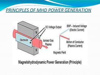
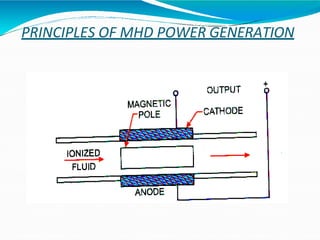
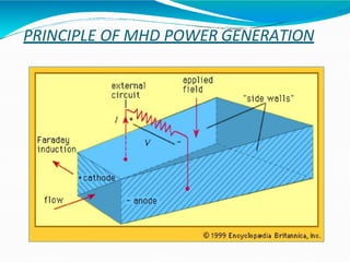
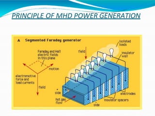
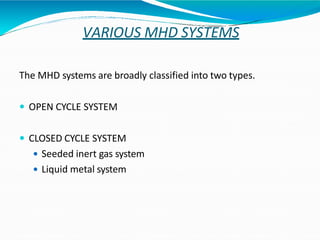
SWAMI PARMANAND COLLEGE OF
ENGINEERING & TECHNOLOGY
SEMINAR
ON
MAGNETO HYDRO DYNAMIC POWER GENERATION
Submitted To:- Submitted By:-
Er. Kapil Sethi Alok Kumar
H.O.D of E.E.E Deptt. Roll No:-1611787
Sem. EEE Branch/ 7th
CONTENTS
o INTRODUCTION
o PRINCIPLE
o VARIOUS SYSTEM
o ADVANTAGES
o LIMITATIONS
o PROBLEMS ENCOUNTERED
o CONCLUSION
INTRODUCTION
MHD power generation is a new system of electric power
generation which is said to be of high efficiency and low
pollution.
As its name implies, Magneto Hydro Dynamics (MHD) concerned
with the flow of a conducting fluid in the presence of magnetic and
electric field. The fluid may be gas at elevated
temperatures or liquid metals like sodium or potassium.
Magnetohydrodynamics (MHD) (magneto fluid
dynamics or hydromagnetics) is the studyof
the dynamics of electrically conducting fluids. Examples
of such fluids include plasmas, liquid metals, and salt
water orelectrolytes.
The field of MHD was initiated by Hannes Alfven, forwhich
PRINCIPLES OF MHD POWER GENERATION
When an conductor moves across a magnetic field, a
voltage is induced in itwhich producesan electric current.
This is the principleof theconventional generatorwhere the
conductors consist of copperstrips.
In MHD generator, the solid conductors are replaced by a
gaseous conductor, an ionized gas. If such agas is passed at a
high velocity through a powerful magnetic field, a current is
generated and can be extracted by placing electrodes in
suitable position in thestream.
The principle can be explained as follows: An conductor
moving through a magnetic field experiences a retarding
forceas well as an induced electric field and current
PRINCIPLE OF MHD POWER GENERATION
The flow direction is right angles to the magnetic fields
direction. An electromotive force (or electric voltage) is
induced in the direction at right angles to both flow and
field directions.
PRINCIPLES OF MHD POWER GENERATION
PRINCIPLE OF MHD POWER GENERATION
 The conducting flow fluid is forced between the plates with a
kinetic energy and pressure differential sufficient to over come
the magnetic induction force.
 An ionized gas is employed as the conducting fluid.
 Ionization is produced either by thermal means I.e. by an
elevated temperature or by seeding with substance like
cesium or potassium vapors which ionizes at relatively low
temperatures.
 The atoms of seed element split off electrons. The presence of
the negatively charged electrons makes the gas an electrical
conductor.
 Theend view drawing illustrates theconstruction of the
flow channel.
PRINCIPLE OF MHD POWER GENERATION
VARIOUS MHD SYSTEMS
The MHD systems are broadly classified into two types.
 OPEN CYCLE SYSTEM
 CLOSED CYCLE SYSTEM
 Seeded inert gas system
 Liquid metal system
OPEN CYCLE SYSTEM
 The fuel used maybe oil through an oil tank or gasified coal
through a coal gasification plant.
 The fuel (coal, oil or natural gas) is burnt in the combustor or
combustion chamber.
 The hot gases from combustor is then seeded with a small
amount of ionized alkali metal (cesium or potassium) to
increase the electrical conductivity of the gas.
 The seed material, generally potassium carbonate is injected
into the combustion chamber, the potassium is then ionized by
the hot combustion gases at temperature of roughly 2300’ c to
2700’c.
OPEN CYCLE SYSTEM
 Toattain such high temperatures, the compressed air is
used to burn the coal in the combustion chamber, must be
adequate to at least 1100’c.
 The hot pressurized working fluid living in the combustor
flows through a convergent divergent nozzle. In passing
through the nozzle, the random motion energy of the
molecules in the hot gas is largely converted into directed,
mass of energy. Thus , the gas emerges from the nozzle
and enters the MHD generator unit at a high velocity.
CLOSED CYCLE SYSTEM
 Two general types of closed cycle MHD generators are
being investigated.
 Seeded Inert Gas System
 Liquid Metal System
SEEDED INERT GAS SYSTEM
 In a closed cycle system the carrier gas operates in the form of
Brayton cycle. In a closed cycle system the gas is compressed
and heat is supplied by the source, at essentially constant
pressure, the compressed gas then expands in the MHD
generator, and its pressure and temperature fall.
 After leaving this generator heat is removed from the gas by a
cooler, this is the heat rejection stage of the cycle. Finally the
gas is recompressed and returned for reheating.
LIQUID METAL SYSTEM
 When a liquid metal provides the electrical conductivity, it is
called a liquid metal MHD system.
 The carrier gas is pressurized and heated by passage through
a heat exchanger within combustion chamber. The hot gas is
then incorporated into the liquid metal usually hot sodium
or Lithium to form the working fluid.
 The working fluid is introduced into the MHD generator
through a nozzle in the usual ways. The carrier gas then
provides the required high direct velocity of the electrical
conductor.
ADVANTAGES
 The conversion efficiency of a MHD system can be around
50% much higher compared to the most efficient steam
plants.
 Large amount of power is generated.
 It has no moving parts, so more reliable.
 The closed cycle system produces power, free of pollution.
 It has ability to reach the full power level as soon as started.
 The size of the plant is considerably smaller than
conventional fossil fuel plants.
LIMITATIONS
 The metallic vapours are poor electrical conductors.
 High velocities cannot be obtained by expansion in the system
while it is much easier to achieve a high fluid velocity .
 employing a gas and a nozzle. This is because the liquids are
practically in compressible.
 The overall conversions efficiencies obtainable with liquid
metal system are quite below to that of plasma system.
APPLICATIONS
 Laser power MHD Generators.
 Plasma physics applications.
 Power generation in space crafts.
 Hypersonic wind tunnel experiments.
 Defense applications.
PROBLEMS ENCOUNTERED
 Seed material potassium attacks insulating materials and make
them conducting.
 Electrode materials are chemically eroded by combustion of
gases.
 It has been reported that capital costs of MHD plants will be
competitive to conventional steam plants.
 Most of the problems are related to material problems caused
by high temperature and highly corrosive and abrasive
environment.

.pptx

  • 1.
    SWAMI PARMANAND COLLEGEOF ENGINEERING & TECHNOLOGY SEMINAR ON MAGNETO HYDRO DYNAMIC POWER GENERATION Submitted To:- Submitted By:- Er. Kapil Sethi Alok Kumar H.O.D of E.E.E Deptt. Roll No:-1611787 Sem. EEE Branch/ 7th
  • 2.
    CONTENTS o INTRODUCTION o PRINCIPLE oVARIOUS SYSTEM o ADVANTAGES o LIMITATIONS o PROBLEMS ENCOUNTERED o CONCLUSION
  • 3.
    INTRODUCTION MHD power generationis a new system of electric power generation which is said to be of high efficiency and low pollution. As its name implies, Magneto Hydro Dynamics (MHD) concerned with the flow of a conducting fluid in the presence of magnetic and electric field. The fluid may be gas at elevated temperatures or liquid metals like sodium or potassium. Magnetohydrodynamics (MHD) (magneto fluid dynamics or hydromagnetics) is the studyof the dynamics of electrically conducting fluids. Examples of such fluids include plasmas, liquid metals, and salt water orelectrolytes. The field of MHD was initiated by Hannes Alfven, forwhich
  • 4.
    PRINCIPLES OF MHDPOWER GENERATION When an conductor moves across a magnetic field, a voltage is induced in itwhich producesan electric current. This is the principleof theconventional generatorwhere the conductors consist of copperstrips. In MHD generator, the solid conductors are replaced by a gaseous conductor, an ionized gas. If such agas is passed at a high velocity through a powerful magnetic field, a current is generated and can be extracted by placing electrodes in suitable position in thestream. The principle can be explained as follows: An conductor moving through a magnetic field experiences a retarding forceas well as an induced electric field and current
  • 5.
    PRINCIPLE OF MHDPOWER GENERATION The flow direction is right angles to the magnetic fields direction. An electromotive force (or electric voltage) is induced in the direction at right angles to both flow and field directions.
  • 6.
    PRINCIPLES OF MHDPOWER GENERATION
  • 7.
    PRINCIPLES OF MHDPOWER GENERATION
  • 8.
    PRINCIPLE OF MHDPOWER GENERATION
  • 9.
    PRINCIPLE OF MHDPOWER GENERATION  The conducting flow fluid is forced between the plates with a kinetic energy and pressure differential sufficient to over come the magnetic induction force.  An ionized gas is employed as the conducting fluid.  Ionization is produced either by thermal means I.e. by an elevated temperature or by seeding with substance like cesium or potassium vapors which ionizes at relatively low temperatures.  The atoms of seed element split off electrons. The presence of the negatively charged electrons makes the gas an electrical conductor.  Theend view drawing illustrates theconstruction of the flow channel.
  • 10.
    PRINCIPLE OF MHDPOWER GENERATION
  • 11.
    VARIOUS MHD SYSTEMS TheMHD systems are broadly classified into two types.  OPEN CYCLE SYSTEM  CLOSED CYCLE SYSTEM  Seeded inert gas system  Liquid metal system
  • 12.
    OPEN CYCLE SYSTEM The fuel used maybe oil through an oil tank or gasified coal through a coal gasification plant.  The fuel (coal, oil or natural gas) is burnt in the combustor or combustion chamber.  The hot gases from combustor is then seeded with a small amount of ionized alkali metal (cesium or potassium) to increase the electrical conductivity of the gas.  The seed material, generally potassium carbonate is injected into the combustion chamber, the potassium is then ionized by the hot combustion gases at temperature of roughly 2300’ c to 2700’c.
  • 13.
    OPEN CYCLE SYSTEM Toattain such high temperatures, the compressed air is used to burn the coal in the combustion chamber, must be adequate to at least 1100’c.  The hot pressurized working fluid living in the combustor flows through a convergent divergent nozzle. In passing through the nozzle, the random motion energy of the molecules in the hot gas is largely converted into directed, mass of energy. Thus , the gas emerges from the nozzle and enters the MHD generator unit at a high velocity.
  • 14.
    CLOSED CYCLE SYSTEM Two general types of closed cycle MHD generators are being investigated.  Seeded Inert Gas System  Liquid Metal System
  • 15.
    SEEDED INERT GASSYSTEM  In a closed cycle system the carrier gas operates in the form of Brayton cycle. In a closed cycle system the gas is compressed and heat is supplied by the source, at essentially constant pressure, the compressed gas then expands in the MHD generator, and its pressure and temperature fall.  After leaving this generator heat is removed from the gas by a cooler, this is the heat rejection stage of the cycle. Finally the gas is recompressed and returned for reheating.
  • 16.
    LIQUID METAL SYSTEM When a liquid metal provides the electrical conductivity, it is called a liquid metal MHD system.  The carrier gas is pressurized and heated by passage through a heat exchanger within combustion chamber. The hot gas is then incorporated into the liquid metal usually hot sodium or Lithium to form the working fluid.  The working fluid is introduced into the MHD generator through a nozzle in the usual ways. The carrier gas then provides the required high direct velocity of the electrical conductor.
  • 17.
    ADVANTAGES  The conversionefficiency of a MHD system can be around 50% much higher compared to the most efficient steam plants.  Large amount of power is generated.  It has no moving parts, so more reliable.  The closed cycle system produces power, free of pollution.  It has ability to reach the full power level as soon as started.  The size of the plant is considerably smaller than conventional fossil fuel plants.
  • 18.
    LIMITATIONS  The metallicvapours are poor electrical conductors.  High velocities cannot be obtained by expansion in the system while it is much easier to achieve a high fluid velocity .  employing a gas and a nozzle. This is because the liquids are practically in compressible.  The overall conversions efficiencies obtainable with liquid metal system are quite below to that of plasma system.
  • 19.
    APPLICATIONS  Laser powerMHD Generators.  Plasma physics applications.  Power generation in space crafts.  Hypersonic wind tunnel experiments.  Defense applications.
  • 20.
    PROBLEMS ENCOUNTERED  Seedmaterial potassium attacks insulating materials and make them conducting.  Electrode materials are chemically eroded by combustion of gases.  It has been reported that capital costs of MHD plants will be competitive to conventional steam plants.  Most of the problems are related to material problems caused by high temperature and highly corrosive and abrasive environment.