Downloaded 117 times
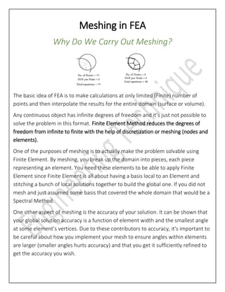
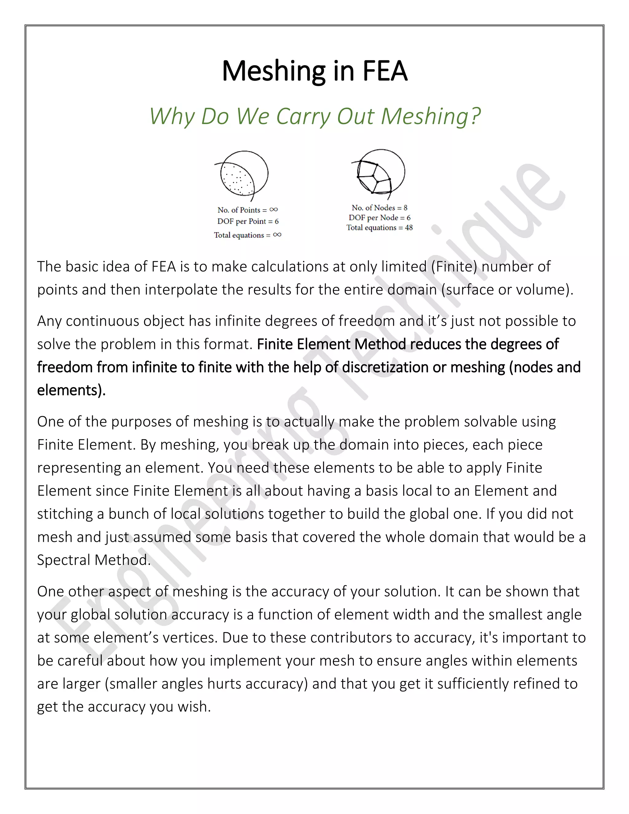
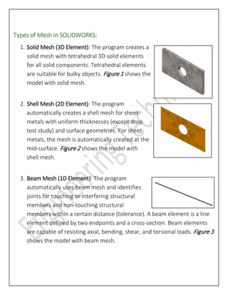

The document explains the importance of meshing in finite element analysis (FEA), emphasizing that it allows for the reduction of infinite degrees of freedom to a finite number, making problems solvable. It details the types of mesh used in software like SolidWorks, including solid, shell, and beam meshes, and outlines the procedure for preparing a model for simulation by focusing on relevant components. Additionally, it highlights the significance of mesh accuracy, influenced by element size and angles in vertices.