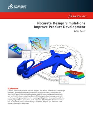
Accurate Design Simulation Improves Product Development
•
2 likes•225 views

Learn how SOLIDWORKS Simulation allows you to accurately solve complex analysis problems, helping you overcome time, budget, and quality challenges.

Recommended
More Related Content
Similar to Accurate Design Simulation Improves Product Development
Similar to Accurate Design Simulation Improves Product Development (20)
More from Engineering Technique
More from Engineering Technique (20)
Recently uploaded
Recently uploaded (20)
Accurate Design Simulation Improves Product Development
- 1. SUMMARY Creating innovative products requires insights into design performance, and design engineers who can predict design behavior are more efficient, innovative, and successful. With SOLIDWORKS Simulation 3D CAD integrated analysis solutions, you can intuitively, accurately, and cost-effectively simulate how a product will perform, enabling you to dimension precisely and optimize designs while reducing prototyping and time-consuming trials processes. SOLIDWORKS Simulation allows you to accurately solve complex analysis problems, helping you overcome time, budget, and quality challenges. Accurate Design Simulations Improve Product Development White Paper
- 2. Accurate Design Simulations Improve Product Development 1 HOW SIMULATION ACCURACY BENEFITS PRODUCT DEVELOPMENT Developing successful products demands innovation, reliability, and speed. As a design engineer, you not only must satisfy form, fit, and function requirements, you must also create unique, dependable, and manufacturable product designs faster and at lower cost. To achieve these goals, you need to have as much information as early as possible about how your design will perform under real-world operating conditions without resorting to costly, time-consuming rounds of physical prototype testing or outsourced simulations. With integrated SOLIDWORKS Simulation solutions, you can run accurate FEA simulations right inside SOLIDWORKS CAD software, giving you fast access to structural analysis results early in the development process, such as stress level, deformed shape, product lifespan, etc. With this vital information, you can make critical design decisions that help you: • Create product innovations • Reduce prototyping • Accelerate time-to-market • Optimize material usage • Eliminate design uncertainty • Minimize field performance issue • Decrease warranty claims and returns • Boosts profitability. With its intuitive user interface, powerful solvers, and extensive analysis capabilities, SOLIDWORKS Simulation gives you an integrated design analysis solution that is not only faster and easier to use, but also just as accurate as any other simulation package. This paper will examine analysis accuracy and how the unique combination of precision, ease of use, and power in SOLIDWORKS Simulation software can benefit your product development effort. ACCURATELY SIMULATING THE EFFECTS OF THE SOLAR WIND The Smithsonian Astrophysical Observatory (SAO), part of the Harvard-Smithsonian Center for Astrophysics (CFA), works with leading astrophysicists and scientists on the development of cutting- edge research instruments and systems. SAO leverages SOLIDWORKS Simulation Premium software to tackle some of the most difficult engineering challenges, such as mankind’s first visit to a star. The U.S. National Aeronautics and Space Administration (NASA) Solar Probe Plus (SPP) will launch in 2018. The car-sized spacecraft will plunge directly into the sun’s atmosphere. SAO’s role is to develop the Solar Wind Electrons Alphas and Protons (SWEAP) payload, including a Faraday sensor that will measure the properties of electrons, protons, and helium ions in the solar wind. What makes the project so challenging is that the sensor resides on the exterior of the spacecraft, where it will be subjected to intense heat and radiation. “The sensor operates in an environment so extreme that we have to use integrated analysis tools,” says Project Engineer David R. Caldwell. “We recently ran prototype tests at the Solar Wind Facility at the Marshall Space Flight Center, and the sensor performed as predicted by our SOLIDWORKS simulations. “With space flight systems, weight is critical,” Caldwell adds. “SOLIDWORKS Simulation Premium gives us the information we need to change thicknesses or materials and truly optimize our designs.” “I can solve a nonlinear simulation problem that used to take a week in a few hours. With that kind of speed, I can quickly optimize and deliver a design that will perform.” David R. Caldwell Project Engineer Smithsonian Astrophysical Observatory
- 3. Accurate Design Simulations Improve Product Development 2 HOW ACCURATELY DOES FEA SIMULATE REALITY? In general, FEA systems utilize the finite element method, a discrete numerical technique for approximating solutions to boundary value problems for the differential equations that govern physics and engineering. The model is represented as a discretization of the geometry—meshing the geometry with elements. Because FEA solutions, regardless of the package, are based on the finite element method, their solutions will always be an approximation—close enough to provide the accuracy required to make important design decisions but never perfectly 100-percent reflective of reality—and include a discretization error. FEA solvers utilize computational algorithms to generate differential equations for each component from design geometry, constraints, material properties, and loads. They then convert the differential equations into matrix equations for each element to generate a global matrix equation for the model. This is generally solved using direct-sparse or iterative solvers: direct-sparse solvers use the Gaussian elimination method to solve the global matrix equation; iterative solvers use the domain-decomposition method. The mathematical underpinnings of FEA mean that engineers must accurately apply loads and boundary conditions in order to get as close to the real answer as you can. Because FEA represents a close approximation of design performance, simulating reality as accurately as possible demands that the analysis problem is set up correctly. The real question regarding how accurately FEA simulates reality is: How accurate do you need to be? In most cases, being within ±5 percent will provide the necessary insights for making the right design decisions. ACCURATE SIMULATIONS FACILITATE WATERPROOF ENCLOSURE DEVELOPMENT Watershot, Inc., designs and manufactures waterproof enclosures for use on cameras by professional underwater photographers and cinematographers, and for use on smartphones by scuba, snorkel, and free-dive enthusiasts. The company relies on SOLIDWORKS Simulation analysis software to ensure that its watertight enclosures withstand the pressures and forces associated with various depths underwater. The company’s engineers have come to value the intuitive integration of SOLIDWORKS CAD and FEA software because it accelerates development. With SOLIDWORKS integrated design analysis tools, Watershot can rapidly create design concepts and simulate their performance at various depths underwater. Because Watershot engineers can accurately simulate product behavior, they can refine designs while avoiding costly prototypes. For example, during development of the waterproof enclosure for the iPhone 4, tooling samples revealed that the enclosure pressed against the smartphone’s touch screen at a certain depth, preventing the phone from functioning. SOLIDWORKS Simulation software enabled Watershot to solve this classic deflection problem and optimize the design without making substantial tooling changes. “We’ve periodically looked at other development solutions, but SOLIDWORKS has always come out on top,” stresses Project Engineer Stephanie Griffin Peña. “The software provides everything we need, and the way that Simulation works with the CAD package really streamlines the process.” “SOLIDWORKS Simulation allows us to understand the influence of underwater pressure and forces during design, which saves time and money.” Stephanie Griffin Peña Project Engineer Watershot, Inc.
- 4. Accurate Design Simulations Improve Product Development 3 WHAT CAN YOU SIMULATE? Finite Element Analysis (FEA) and computational fluid dynamics (CFD) simulation technology allows you to use computer-based, mathematical modeling to approximate and simulate the complex phenomena of the physical universe, including structural, heat transfer, fluid flow, and dynamic behaviors. Structural Analysis You can use FEA software to simulate the various behaviors involved with solid mechanics. Will the stresses created within a structure—whether it’s a machine component or a bridge truss— under operational loads cause it to break, buckle, yield, or deform? What are a structure’s natural frequencies and how will they impact design performance? What about displacement, vibration, or fatigue? When creating designs in which two or more components come in contact with one another, you can discover how this contact affects design performance. You can also conduct kinematics studies and use those results to learn important load information for running subsequent structural analyses. Structural Analysis provides Stress distribution to identify critical areas
- 5. Accurate Design Simulations Improve Product Development 4 Thermal Analysis Understanding how heat transfer impacts design performance is important for an increasing number of products for safety and performance reasons. Many materials have temperature- dependent properties, and you can use simulation software to simulate different types of heat transfer—including conduction, convection, or radiation—and calculate heat transfer within and between components in your design and its environment. You can simulate transient and steady-state effects. Thermal problems can be solved using either structural or fluid flow analysis. In a thermal structural analysis, the effect of moving air or liquid becomes a load or boundary condition. In a fluid flow analysis, you can calculate the thermal effects of moving fluids, whether it’s a liquid or a gas. Computational Fluid Dynamics Analysis You can use computational fluid dynamics (CFD) analysis software to meet the continually growing need to understand how the behavior and dynamics of fluids—either liquids or gases— affect design performance. Although initially used primarily as an alternative to expensive wind-tunnel testing for improving the aerodynamics of aircraft and automobiles, SOLIDWORKS Flow Simulation CFD analysis technology is now increasingly used to evaluate other flow- related issues, such as validating sufficient cooling of electronics; maximizing the performance of heating, ventilation, and air-conditioning (HVAC) systems; and refining other flow-based manufacturing processes. Thermal Analysis helps Product Engineers to predict overheating issues early in the design process Thermal Analysis helps Product Engineers to predict overheating issues early in the design process
- 6. Accurate Design Simulations Improve Product Development 5 Linear or Nonlinear FEA Although you can use linear FEA analysis tools to simulate the behavior of many types of designs, some physical phenomena are nonlinear in nature. In other words, the physical response is disproportionate to the applied loads and boundary conditions. Whenever you are dealing with nonlinear materials such as rubber or plastic, nonlinear geometries, nonlinear interactions between parts, or nonlinear loads and boundary conditions, you need to run nonlinear FEA analyses to improve the accuracy of the approximation. SIMULATION ACCURACY DRIVES ENTRY INTO INDUSTRIAL DAMPER MARKET The need to restrict gases and liquids in many factories and plants—including power plants, steel mills, cement plants, petrochemical facilities, and other process-related operations— makes industrial dampers a necessity. DEMECH Esscano Power India Pvt. Ltd. (DEP), a joint venture of Esscano Power A/S Denmark and Deccan Mechanical & Chemical Industries Pvt. Ltd., was founded to meet the challenging requirements for damper technology. DEP designs and manufactures many types of industrial dampers, including multilouver dampers, butterfly dampers, sliding dampers, and other variants. The company has quickly attained a prominent role in the industrial damper market, introducing new concepts that offer performance and cost advantages. Using SOLIDWORKS Simulation Premium and SOLIDWORKS Flow Simulation software, DEP has eliminated the need to prototype and test its systems. The company relies on SOLIDWORKS simulation tools to support its goal of producing dampers that are 99.95 to 100 percent efficient. “We started using SOLIDWORKS simulation for calculating thermal expansion of the blades while working under extremely high temperatures,” says General Manager Subhash Bidwai. “We need to provide adequate clearances to account for this expansion while still preventing leaks that hamper efficiency. With the accurate simulations provided by SOLIDWORKS, there’s really no need to build a prototype and test.” “With the accurate simulations provided by SOLIDWORKS, there’s really no need to build a prototype and test.” Subhash Bidwai General Manager DEMECH Esscano Power India Pvt. Ltd.
- 7. Accurate Design Simulations Improve Product Development 6 Q & A WITH FEA EXPERT DR. PAWEL M. KUROWSKI Dr. Pawel M. Kurowski, an Assistant Professor in the Faculty of Engineering at the University of Western Ontario, is a leading expert in the fields of product design, design analysis, and solid mechanics. Prior to becoming a professor, Dr. Kurowski worked for over 20 years as a design and R&D engineer in automotive, defense, and heavy equipment industries. Why did you decide to standardize on SOLIDWORKS Simulation solutions as the preferred tool for your engineering curriculum? I am a huge proponent of design engineers using FEA tools because they have the most complete understanding of a product’s operating environment and design intent, and are in the best position to use FEA to optimize designs early in the process. We standardized on SOLIDWORKS Simulation software because it is completely integrated with and directly interfaced to the SOLIDWORKS 3D modeling environment, making the solution easier to learn and use. How do you utilize SOLIDWORKS Simulation software in your engineering program? We use SOLIDWORKS Simulation in our undergraduate and graduate FEA courses. One of these courses—Advanced Computer-Aided Engineering (CAE)—combines the use of SOLIDWORKS Simulation, SOLIDWORKS Flow Simulation and SOLIDWORKS Motion Simulation to examine different types of physical phenomena that can affect design performance. The software’s powerful range of capabilities allows students to interrogate design behavior from all angles, whether it be structural, fluid flow, thermal, motion, vibration, design for manufacturability, or sustainability. SOLIDWORKS Simulation and SOLIDWORKS Flow Simulation provide the widest range of FEA and CFD capabilities within a single-window design and analysis environment. By using SOLIDWORKS Simulation software, we provide students with a sound foundation in numerical design analysis. Does CAD integration and ease of use make SOLIDWORKS Simulation any less powerful than other FEA packages? No. Actually, the opposite is the case. SOLIDWORKS Simulation is more powerful than other FEA packages because it is easier to learn and faster to use. All FEA programs are based on the finite element method, and the math is pretty much the same underneath. SOLIDWORKS Simulation excels because its integration with CAD modeling, intuitive user interface, well-designed solvers, mesh controls, and range of analysis types are superior. Did making SOLIDWORKS Simulation easy to use make it any less accurate? No. Just because the software is easy to use doesn’t mean that it’s been dumbed down or made to be less accurate. Accuracy in FEA depends on properly defining the problem, gaining an understanding of the type of analysis to be run, and maintaining the integrity of the mathematical model. No FEA program is 100-percent accurate because they all utilize the same numerical discretization techniques. In terms of accuracy, SOLIDWORKS Simulation is just as strong as anything else. I would argue that because SOLIDWORKS Simulation is easier to use, it makes accurately setting up the analysis problem more straightforward, leading to more accurate results.
- 8. Accurate Design Simulations Improve Product Development 7 How can users increase the accuracy of FEA results? There are two areas that can influence accuracy in FEA packages. One is correctly setting up the problem by using the correct type of analysis, inputting accurate material properties, loads, and boundary conditions, and selecting the right elements for the type of analysis that you are running. The other is controlling the size of the discretization error using adaptive methods and mesh controls. Discretization error is inherent in FEA; you can control it manually with mesh controls or automatically by using h-adaptive or p-adaptive meshing. In SOLIDWORKS Simulation, you can use these techniques to refine the automatically generated mesh in areas of interest. The h-adaptive approach increases the number of elements in the area of interest to increase accuracy while the p-adaptive technique increases the order of the polynomials used to approximate the displacement field for elements in areas with high estimated errors to improve accuracy. How accurate do FEA results need to be? That’s the question that design engineers should ask themselves before running an analysis. Accuracy depends on: 1. How well the problem has been defined in terms of the type of analysis, material properties, boundary conditions, etc. We call this modeling error. Problem definition and the associated modeling error are external to FEA. Control of modeling error is a matter of correct defining the problem. 2. How well the problem has been discretized. This is called discretization error. In most cases, accuracy within a few percent is sufficient, but SOLIDWORKS Simulation gives you tools to make it as low as you wish—from simple manual mesh refinements to advanced automatic h-adaptive solutions. 3. How well the problem has been solved. This is the numerical round-off error accumulated by the solver. In SOLIDWORKS Simulation, this error is minimized by the use of fast and well-designed solvers.
- 9. Accurate Design Simulations Improve Product Development 8 PRECISE SIMULATION RESULTS SPARK THERMAL IMAGING CAMERA INNOVATIONS FLIR Systems, Inc., is the world’s leading manufacturer of thermal imaging infrared cameras. The company relies on SOLIDWORKS Simulation Premium and SOLIDWORKS Flow Simulation software to develop new maritime, security, and handheld thermal imaging applications. For example, during the development of the M Series maritime pan-and-tilt camera, engineers had to decrease the height of the initial design by 1.5 inches, resulting in a temperature rise above the motor’s specification. FLIR made a series of design changes and ran coupled flow/thermal analyses. The process allowed FLIR to modify the design to shave 23ºC off the temperature (a 6ºC cushion) without building a single prototype. “The M Series camera shows how powerful using coupled flow/thermal analysis is,” says Director of Mechanical Engineering Marcel Tremblay. “It’s all about the air inside, and a coupled flow/thermal analysis is more accurate than just conduction or convection. It allows us to simulate various scenarios to better understand where the low hanging fruit is in terms of design changes without actually prototyping the design. This represented months of time savings. “SOLIDWORKS is the perfect combination of ease of use and power,” Tremblay says. “The CAD system makes modeling easy and the simulation tools allow us to optimize, refine, and improve the reliability of designs.” “We are amazed by the precision of SOLIDWORKS Flow Simulation. With its dead-on precision, we can quickly evaluate innovative approaches.” Marcel Tremblay Director of Mechanical Engineering FLIR Systems, Inc. Does element type affect accuracy? Of course, it does. For example, a thin shell element models linear distribution of in-plane stresses across its thickness. Using this element to model a wall where in-plane stresses do not have linear distribution across the thickness will produce incorrect results. A 2D plane stress element assumes constant stress across its thickness. If we use it to model a problem where stresses do change across the thickness, we’ll again produce incorrect results. The list of “element abuse” is long, and we always have to select elements that are able to model the expected pattern of stress distribution. This applies to any FEA program. An element on its own is neither “accurate” nor “inaccurate”. The term “accuracy” applies to the mesh built out of finite elements. Which are more accurate: Brick or Tetrahedral (Tet) elements? To understand why some FEA users say that hexahedral (brick) elements are more accurate than tetrahedral (tet) elements, we have to travel back in time to the early 1980s. Back then, FEA programs ran on very slow computers by today’s standards. Analysts had to limit the size of a model—which meant using large, first-order elements—just to make it run. For that purpose, first-order brick elements offered significant advantages over first-order tet elements of the same size. This is because the first-order brick elements model second-order field of displacement and linear field of stress, while the first-order tet elements model linear field of displacement and constant stress. Consequently, first-order brick elements behave as second-order tet elements. If you wanted to use tets instead of bricks, you had to use second-order tet elements or first-order tet elements of smaller size. Both options were difficult to implement on 1980s-era computers. Today, nobody uses first-order elements anymore. Large meshes are easily created by auto-meshers, and problems are quickly solved by efficient solvers. The ubiquitous second-order tet elements model second-order field of displacement and first-order field of stress. In modern FEA programs brick elements no longer have any advantages over tets. There remains the question of the aesthetics of a mesh. Many people find brick meshes more aesthetically pleasing even though nicely shaped bricks on the outside faces of the model may hide highly distorted brick or tet elements inside. FEA intimidates some design engineers. Why? Because many FEA packages are so difficult to use, it’s extremely challenging for design engineers to obtain meaningful results with them without a lengthy period of intensive training. This is why SOLIDWORKS Simulation software is my preferred FEA solution. It makes it easier to set up analysis problems and generate accurate, meaningful results. With SOLIDWORKS Simulation software, engineers can be up and running after a couple hours of introductory training.
- 10. Accurate Design Simulations Improve Product Development 9 SOLIDWORKS SIMULATION: ACCURACY + INTUITIVENESS = POWER SOLIDWORKS Simulation solutions carry the greatest potential for improving your product development process because of their unique combination of ease of use, speed, accuracy, and power. With SOLIDWORKS Simulation software, you have access to a versatile array of analysis capabilities—including solver, mesh, and results communication tools—directly from within the SOLIDWORKS CAD modeling environment. Capabilities SOLIDWORKS Simulation solution provides a complete range of analysis types to meet virtually any simulation need, including: • Structural Analysis form simple linear to highly nonlinear problems • Linear and nonlinear vibration analysis • Thermal Analysis–steady state and transient • Fatigue life analysis • Fluid Flow Analysis • Motion Simulation • Coupled-Field Multiphysics Analysis where the above capabilities are combined The SOLIDWORKS Simulation solution also allows you to run many kinds of studies within these analysis types, including: • Static (Stress) • Frequency • Buckling • Fatigue • Vibration • Contact • Assembly • Nonlinear • Dynamic • Modal time history • Harmonic • Random Vibration • Response spectrum • Design Optimization • Kinematics and Dynamics • Plastic and Rubber Components • Fluid Flow • Electronics Thermal Management • Thermal Comfort Factors • Coupled Thermal-Structural • Coupled Thermal-Fluid • Plastic Mold-Filling • Sustainability
- 11. Accurate Design Simulations Improve Product Development 10 Meshers SOLIDWORKS Simulation software allows you to take advantage of its fast automatic mesher as well as flexible and powerful mesh refinement tools, including h-adaptive and p-adaptive capabilities for improving simulation accuracy. You can choose to create solid, shell, beam, or mixed mesh types according to your geometry. You can also choose between 3D and 2D representations of your problem. The tight integration of SOLIDWORKS Simulation inside SOLIDWORKS CAD enable the automatic translation of geometry type into mesh type; weldments into beam, surface into shells. Solvers SOLIDWORKS Simulation FEA software enables you to utilize either direct or iterative solving methods with its Direct Sparse or FFEPlus solvers. The software will automatically select the best solver for your particular analysis. For example, the software will use the Direct Sparse Solver for static, frequency, buckling, and thermal studies, and will default to the FFEPlus iterative solver for nonlinear and contact analyses. For large models—with millions of degrees of freedom (DOF), the large Direct Sparse Solver will be used automatically. Results Communication Once you’ve run an analysis study that you want to document, SOLIDWORKS Simulation software lets you automatically generate an engineering report based on results. You can quickly and easily create animations to highlight the results of structural, thermal, motion, and fluid-flow studies. You can also save out analysis results in a compact SOLIDWORKS eDrawings file, which allows you to communicate results via email, tablets, and smartphones. CAD Integration What truly differentiates SOLIDWORKS Simulation software from other FEA packages is its complete integration inside the SOLIDWORKS CAD modeling environment. With SOLIDWORKS Simulation, there’s no need to import or export models to either run an analysis or modify models based on simulation results, and then run the analysis again. Because all FEA and CFD simulations take place within the SOLIDWORKS CAD modeling environment, you can more efficiently leverage Simulation during the initial design phase. You can also take advantage of CAD tools such as design configurations to run a family of analyses on a single model, a single analysis on a family of models, or some mixture of the two. You can also leverage the CAD data—such as material properties, parts positioning (mates), or fastener definitions—to streamline the setup of your simulations. FAST, ACCURATE SIMULATIONS ACCELERATE TRANSMISSION SYSTEMS DESIGN Litens Automotive Group is the global leader in the design and manufacture of engineered power transmission systems and components. A tier 1 supplier to the automotive industry, Litens has maintained its market leadership position by continuously developing innovative products that solve vehicle performance and noise, vibration, and harshness (NVH) challenges. By using SOLIDWORKS Simulation Premium software to conduct simulations as an integral part of the design process, Litens has reduced prototyping iterations and associated costs, while accelerating its development process. The company’s engineers conduct very complicated contact analyses—as well as kinematics, dynamics, fatigue, displacement, and thermal simulations—directly within the SOLIDWORKS design environment. “Time is the critical factor, and with the fast solver in SOLIDWORKS Simulation Premium software, we can solve a full-assembly contact analysis in a couple of hours. Who else can do that?” says Chief Engineer Dr. Steve Jia. “When you consider the time and prototyping costs that virtual product development using CAE helps us save, it amounts to millions of dollars each year. “The beauty of SOLIDWORKS Simulation Premium software is that it offers a robust mesher, a fast solver, and the ability to handle very large assembly simulations with very complicated contact situations easily,” Dr. Jia adds. “We’ve realized outstanding ROI (return on investment) with SOLIDWORKS Simulation Premium and rely on the software for our daily work.” “As we design products, we need to be able to run a range of simulation studies—from complicated contact finite element analysis to design optimization, sensitivity, motion analysis, and fatigue studies. We needed an FEA solution that can not only handle all of these types of analyses, but also produce accurate results right away. That solution is SOLIDWORKS Simulation Premium.” Dr. Steve Jia Chief Engineer, CAE Technologies and Materials Engineering Litens Automotive Group
- 12. Accurate Design Simulations Improve Product Development 11 VERIFYING SOLIDWORKS SIMULATION ACCURACY You can verify the accuracy of SOLIDWORKS Simulation results through verification problems and benchmarks from the National Agency for Finite Element Methods and Standards (NAFEMS), which are included with the software. SOLIDWORKS Simulation software includes verification problems for all types of analysis, which compare SOLIDWORKS Simulation FEA results to known analytical solutions. The software also includes NAFEMS benchmarks for static, thermal, nonlinear, frequency, and linear dynamic studies. NAFEMS benchmarks document the accuracy of analysis results for all commercially available FEA packages. Examples of SOLIDWORKS Simulation and NAFEMS verification problems follow. Bending of a Cantilever Beam Description Calculate the maximum deflection and maximum rotation (θ) of a cantilever beam loaded by a shear force of magnitude 1 lbf acting on the free end of the cantilever. The length of the cantilever is 10” and the dimensions of its cross section are 1”X1”. The cantilever beam is modeled as two identical cantilevers connected at their common interface with a Bonded contact condition. Study Type Static Mesh Type Solid mesh and Beam mesh in separate studies Material Properties Modulus of elasticity = 1 X 10⁶ psi, Poisson’s ratio = 0.4 Results Theory SOLIDWORKS Simulation Solid Mesh SOLIDWORKS Simulation Beam Mesh Displacement at the free end (UX), in -0.004 -0.004 -0.004 Rotation at the free end (RY), rad -0.0006 NA -0.0006 Analytical Solution Displacement at free end: UX = (2* P*L3 ) / ( 6* E*I ) End rotation: θ = 3 * UX / (2*L) where: • P: Shear force • L: Beam length • E: Modulus of elasticity • I: Area moment of inertia
- 13. Accurate Design Simulations Improve Product Development 12 Frequencies of a Triangular Wing Description Calculate the natural frequencies of a right-angle isosceles triangle wing. The equal sides of the triangle are 6” in long and the thickness is 0.034”. One of the equal sides of the triangle is fixed. Study Type Frequency Mesh Type Shell mesh Material Parameters Shell thickness = 0.034 in - Thin formulation Material Properties Modulus of elasticity = 6.5 x 10⁶ psi, Poisson’s ratio = 0.3541, Density = 0.06411 lb/in3 Results Frequency No. Theory (Hz) SOLIDWORKS Simulation (Hz) Draft mesh High quality mesh 1 55.9 55.917 55.925 2 210.9 211.130 211.363 3 293.5 292.701 293.198 Reference “ASME Pressure Vessel and Piping 1972 Computer Programs Verification, by I.S. Tuba and W. B. Wright, ASME Publication I-24, Problem 2.
- 14. Accurate Design Simulations Improve Product Development 13 Steady State Heat Flow in an Orthotropic Plate Description A 1mX2mX0.1m rectangular plate is generating heat at a rate of Q = 100 w/m3 . Two adjacent edges are insulated and the two other edges are dissipating heat to the atmosphere at 0º C. The plate has orthotropic properties. Determine the steady state temperature distribution in the plate. Study Type Steady state thermal analysis. Mesh Type Shell mesh. Shell Parameters Shell thickness = 0.1 m – Thin shell formulation. Material Properties and Other Inputs Thermal conductivity in X = KX = 10 w/(m.K), Thermal conductivity in Y = KY = 0 w/(m.ºK ). Convection coefficient along the long edge = h1 = 10 w/m2 .K. Convection coefficient along the short edge = h2 = 1 = 20 w/m2 .K. Modeling Hints One half of the plate is modeled. Insulated conditions are automatic when no other condition is applied. Results The graph of the temperature variation in the X direction along the bottom edge of the model is shown in the figure below. The graph is in good agreement with reference results. Reference M. N. Ozisik, “Heat Conduction,” Wiley, New York, 1980.
- 15. Accurate Design Simulations Improve Product Development 14 NAFEMS NONLINEAR ANALYSIS BENCHMARKS Torsional Buckling of a Cantilever Determine the tip Z deflection for a cantilever subjected to a constant load of P = 0.017 N along the Y direction. Fix the edge AB of the cantilever. The problem is solved for the conservative loading case. A tiny lateral load is added to simulate the applied imperfection for the incremental nonlinear analysis. Study Type Nonlinear static with large displacement formulation Mesh Type Shell mesh Mesh Size Use a standard mesh with global element size of 1.5 mm. Shell Parameters Shell thickness = 0.2 mm - Thin shell formulation Material Properties • Elasticity modulus (E) = 10 x 103 N/mm2 • Poisson’s ratio (v) = 0 Results Define a Workflow Sensitive sensor at the target location, and use the Probe tool to plot the graph for the UZ displacement component. Process the results using graphing software to generate the graph. The X-axis shows the UZ displacement component in mm and Y-axis shows applied load in N. The load-deflection curve agrees with the finite element solution provided in the reference. Reference NAFEMS Publication R0065, The International Association for the Engineering Analysis Community, “Background to Finite Element Analysis of Geometric Non-linearity Benchmarks, 1999”.
- 16. Accurate Design Simulations Improve Product Development 15 NAFEMS FORCED VIBRATION BENCHMARKS Simply-Supported Thin Plate Under Suddenly- Applied Pressure Calculate the peak UZ displacement and bending stress (SY or SX) at the center of a simply-supported square plate of side 10 m and thickness 0.05 m subjected to a suddenly-applied normal pressure of 100 N/m2. Study Type Three shell studies are created: Study Name Study Type Modal_Damping Linear Dynamics - Transient (modal damping) Rayleigh_Damping Linear Dynamics - Transient (Rayleigh damping) Static Static Mesh Type Shell mesh for all three studies. Shell thickness = 0.05 m – Thin shell formulation. Material Properties Linear elastic isotropic. Modulus of elasticity (E) = 2 x 10¹¹ N/m2, Mass density (ρ) = 8000 Kg/m3, Poisson’s ratio (ν) = 0.3. Load Suddenly-applied normal pressure load of 100 N/m2 to the whole face. Horizontal axis is time (sec) and vertical axis is pressure (N/m2). Dynamic Options • Number of mode shapes = 16 • Solution time = 1.2 sec • Time step = 0.002 sec Damping • Modal_damping: 2% of critical damping for all 16 modes • Rayleigh_damping: Mass coefficient a0 = 0.299, Stiffness coefficient a1 = 1.339 x 10⁻³ .
- 17. Accurate Design Simulations Improve Product Development 16 Results The UZ displacement and bending stress response graphs at the center of the plate are in agreement with the analytical results. The graph depicts the UZ displacement time history at the center of the plate. Horizontal axis is time (sec) and vertical axis is UZ(mm). SOLIDWORKS Simulation Reference Modal _Damping Rayleigh_Damping Peak UZ displacement at center 3.523 mm (t = 0.21 sec) 3.445 mm (t = 0.21 sec) 3.457 mm (t = 0.21 sec) Peak bending stress at center 2.484 N/mm2 2.360 N/mm2 2.296 N/mm2 Steady-state displacement at center 1.817 mm 1.775 mm 1.775 mm Reference NAFEMS, Publication R0016, The International Association for the Engineering Analysis Community, “Selected Benchmarks for Forced Vibration”, Test 13T, 1989.
- 18. ©2018DassaultSystemes.Allrightsreserved.3DEXPERIENCE,CATIA,SOLIDWORKS,SIMULIA,DELMIA,ENOVIA,GEOVIA,EXALEAD,NETVIBES,3DSWYMand3DVIAareregisteredtrademarksofDassaultSystemesoritssubsidiariesintheU.S.and/orother countries.Otherbrandandproductnamesaretrademarksoftheirrespectiveowners.MKTADSWPENG0114 Our 3DEXPERIENCE® platform powers our brand applications, serving 12 industries, and provides a rich portfolio of industry solution experiences. Dassault Systèmes, the 3DEXPERIENCE Company, provides business and people with virtual universes to imagine sustainable innovations. Its world-leading solutions transform the way products are designed, produced, and supported. Dassault Systèmes’ collaborative solutions foster social innovation, expanding possibilities for the virtual world to improve the real world. The group brings value to over 170,000 customers of all sizes in all industries in more than 140 countries. For more information, visit www.3ds.com. Europe/Middle East/Africa Dassault Systèmes 10, rue Marcel Dassault CS 40501 78946 Vélizy-Villacoublay Cedex France Americas Dassault Systèmes 175 Wyman Street Waltham, Massachusetts 02451-1223 USA Asia-Pacific Dassault Systèmes K.K. ThinkPark Tower 2-1-1 Osaki, Shinagawa-ku, Tokyo 141-6020 Japan LEVERAGE SOLIDWORKS SIMULATION ACCURACY TO DRIVE INNOVATION Gaining insights into how a design will perform within its actual operating environment can help you create innovative product designs more efficiently and cost-effectively. With SOLIDWORKS Simulation solution, you can run a range of analyses to obtain accurate design performance information from directly within your SOLIDWORKS CAD modeling environment and forego the need for costly, lengthy rounds of prototyping. Using SOLIDWORKS Simulation solutions will enable you to increase productivity, control costs, eliminate manufacturing issues, minimize performance issues, increase design confidence, and collaborate more effectively. You can use accurate SOLIDWORKS Simulation results to make important design decisions that lead to higher quality and more innovative products at a fraction of the time and cost. To learn more about how powerful, accurate SOLIDWORKS Simulation solutions can improve your development process, visit www.solidworks.com/simulation or call 1 800 693 9000 or 1 781 810 5011.