3. Discretization / Meshing of Structures
The process of modeling / dividing a structure using suitable number,
shape and size of the elements is called discretization or meshing.
The modeling should be good enough to get the results as close to
actual behavior of the structure as possible.
7. What type of element to be apply:
1D, 2D, 3D
What type of element shape to be
apply:
Square, Rectangular, circular,
Tetrahedron, etc
How many number of element to be apply
Mention here numbers
Or
What should be the size of element
Mention the size of element
12. Importance of Element Quality
• The shape of Elements in FE Analysis must be distorted from their Ideal
shapes when meshing the irregular or complex geometric shapes.
• Every element is designed to work properly within a certain range of
shape distortion. Exactly how much distortion and what type of
distortion is allowed before an element degenerate depends on factors
such as element type, numerical procedures used in the element
design, and so forth.
• The Ideal shape of [2D Elements] a triangular element is an equilateral
triangle and a quadrilateral; it is a square.
• The Ideal shape of [3D Elements] a Tetrahedron element is a Regular or
Isosceles Tetrahedron and a Hexahedron, it is a Cube etc.,
• If the actual shape that the element assumes after mapping onto
model geometry differs too much from the natural shape, the element
becomes degenerated and produces erroneous results.
13. Result Quality α Element Quality
• The major types of degeneration are Aspect Ratio, Skewness, Jacobian
Ratio, Warping Factor, Maximum Corner Angle, Orthogonal Quality, Parallel
Deviation, Taper, Curvature distortion and mid-size node position.
• Generally, large angles between edges (close to 180 degree) are more
degenerating than small angles (close to 0 degree).
• Each FE mesh should be run through an element quality check, and
degenerated elements should be eliminated.
• In order to get reasonably accurate results, it is always important to
generate a structured mesh with good quality parameters.
• If Elements are Degenerated, they will become too stiff and underestimate
the deformations (Field Variables) and its derivatives like strain & stress
values become erroneous.
• Degenerated Elements increase the inaccuracy of the finite element
representation and have a detrimental effect on convergence of Finite
Element Solutions.
14. Result Quality α Element Quality
• Now a days most of the FE Simulation softwares are equipped with
In-Built Quality Check Options and Quality Based Mesh Generation
Algorithms.
• Maintaining element quality is always a challenge for analyst during
mesh convergence studies. Though element size is minimized it is of
no use if they are violating quality requirements.
• So, it is important to know how to calculate these parameters for
different Element Shapes. All Element distortions are measured
against Ideal shapes.
• In the subsequent articles we are going to discuss about all the
Quality Parameters and their Calculation. Initially Calculation of
Quality Parameters for 2D elements are discussed later it will be
extended to 3D elements also with the help of 2D calculations.
• Click on the following buttons to get the detailed information of
each Quality Parameter.
19. Mesh Refinement Method
• hP Refinement
– Taking advantages of both h refinement and P
refinement
– It provides Faster convergence than either P
refinement or h refinement
• r refinement
– Node numbers are relocated without changing the
number of element
– All the above methods are convergence method of
priori error estimates
20. Other Methods for Mesh refinement
• Reducing the mesh elements size
• Increasing the element order
• Global Adaptive mesh refinement
• Local Adaptive mesh refinement
• Manually Adjusting the mesh
• Time domain and Frequency Domain
21. Various consideration of discretization/meshing of
structures
a. Nodes at discontinuities
b. Refining mesh
c. Use of symmetry
d. Element aspect ratio
e. Mesh-geometry association
f. Mesh quality
22. A] NODES AT DISCONTINUITIES
In a structure we come across the following types of
discontinuities:
(a) Geometric discontinuity
(b) Discontinuity of Loads
(c) Discontinuity of the Boundary conditions
(d) Material Discontinuity.
23. Geometric Discontinuities
Wherever there is sudden change in shape and size of the structure
there should be a node or line of nodes. Figure shows some of such
situations.
Bar subject to axial forces
Two different Plates
24. Discontinuity of Loads
Concentrated loads and sudden change in the intensity of uniformly
distributed loads are the sources of discontinuity of loads. A node or a
line of nodes should be there to model the structure.
Plate with different UDL
FE model
25. Discontinuity of Boundary conditions
If the boundary condition for a structure suddenly change we have to
discretized such that there is node or a line of nodes.
Slab with intermediate wall and column
26. Material Discontinuity
Node or node lines should appear at the places where material
discontinuity is seen.
Material discontinuity
27. B] REFINING MESH
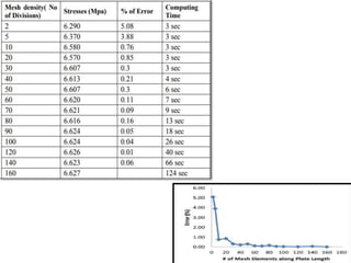
To get better results the finite element mesh should be refined in the
following situations
a. To approximate curved boundary of the structure
b. At the places of high stress gradients.
Refined mesh near curved boundary of a
dam
28. C] USE OF SYMMETRY
Wherever there is symmetry in the problem it should be made use. By
doing so lot of memory requirement is reduced or in other words we can
use more elements (refined mesh) for the same capacity of computer
memory. When symmetry is to be used, it is to be noted that at right angles
to the line of symmetry displacement is zero. In the tension bar example
shown in Fig. biaxial symmetry of the problem is utilized and only quarter
of the bar is taken for the analysis.
Discretization of half of Tension Flat
29. D] ELEMENT ASPECT RATIO
The shape of the element also affects the accuracy of
analysis.
Definition - The ratio of largest to smallest size in an
element
The conclusion of many researchers is aspect ratio should
be as close to unity as possible.
30.
31. G] Mesh Quality
In a finite element mesh, it is generally desirable to avoid
elements of high aspect ratio. The presence of such elements
can have adverse effects on the analysis results.
•In general, such elements can influence analysis results, and
lead to misleading and inaccurate results, which are
dependent on the mesh.
•In extreme cases, such elements may even be responsible
for non-convergence of the finite element solution, and the
analysis will be aborted.
32. Define Mesh Quality
There are three criteria regarding quality of meshing
• ratio of (maximum side length) / (minimum side length)
• Minimum interior angle
• Maximum interior angle
The defaults for the above criteria, are 10 , 20 and 120, respectively. However,
the user may change any of these criteria.
33. Reasons for poor quality mesh elements
There are various reasons why poor quality mesh elements may be
generated. Typically the problems are due to:
1.Poorly graded discretization of model boundaries (for example, a finely
discretized boundary immediately adjacent to, or close to, a coarsely
discretized boundary, will often result in a poor quality mesh).
2.Vertices which are very close to each other. This can happen when a
boundary has been intersected with another boundary, without using vertex
snap, such that two vertices end up very near to each other, when the user
may have intended both vertices to be at the same location. Due to the
automatic boundary intersecting capability of Slide2, this may occur
without the user being aware of it.
3.The geometry of your model boundaries may also be responsible, for
example, the relative distances between boundaries, or the way in which
they intersect (e.g. nearly parallel boundaries which intersect at a very
small angle).
34. Fixing a poor quality mesh
1.If a poor discretization is responsible for the poor mesh, then you will
need to reset the mesh, and modify the discretization of the appropriate
boundaries. This may involve use of the Custom Discretized option, or
simply changing the Approximate Number of Elements in the Mesh
Setup dialog.
2. If the problem is vertices which are very close to each other, then you
may need to delete unnecessary vertices, or move vertices, so that they are
further apart, or exactly coincident. If vertices were intentionally located
very near to each other, and this is causing a problem, then you may want to
consider modifying your geometry slightly, so that poor quality elements are
not generated.
3. If the actual model geometry is responsible, then various solutions might
be appropriate, involving Custom Discretize, or modifying the boundaries
slightly, so that the problem does not occur.
35. F] Mesh-geometry association
Creating an association between orphan mesh entities (elements,
element faces, element edges, and nodes) and adjacent geometry,
allows the transfer of loads, interactions, and boundary conditions
from the geometry to the mesh.
Figure 1 shows an example of the use of mesh-geometry association
between a two-dimensional orphan element region and an adjoining
geometric region.
36. Effect of mesh density in critical region
Mesh Density plays a major role and it becomes a critical issue of
finite element analysis, which closely relates to the accuracy of finite
element model while directly determine their complexity level.
However, as we increase the level of finer meshing in our modeling, the
complexity level of the modeling keeps on increasing. This kind of complex
model always increase the chances of committing mistakes during modeling
and as results, the analysis will show error.
39. a. Geometry size & shape
For analysis software needs all the three dimensions. It
cannot make calculations unless & until geometry is
defined completely (via meshing i.e. nodes and elements).
Geometry could be categorized as 1-d, 2-d or 3-d based on
dominant dimensions and type of element is selected
accordingly.
40. Shape of 1-d element is line. When the element is created
by connecting two points, software comes to know about
only one out of 3 dimensions. Remaining two dimensions
i.e. area of c/s must be defined by the user as additional
input data & assigned to respective elements
Practical Example: Long shaft, rod, beam, column, spot
welding, bolted joints, pin joints, bearing modeling etc.
1-d element:
Used for geometries having one of the dimension very large in
comparison to rest of the two.
41. 2-d meshing is carried out on mid surface of the part. 2-d elements are
planer just like paper of this page. By creating 2-d element software comes
to know 2 out of 3 required dimensions. The third dimension i.e. thickness
has to provided by user as an additional input data.
Why 2-d meshing is carried out on mid surface?
Mathematically element thickness specified by user is assigned half on
element top and half on bottom side. Hence in order to represent the
geometry appropriately it is necessary to extract mid surface & then mesh on
the mid surface.
2-d Element:
Used when two of the dimensions are very large in comparison
to third one.
42. Practical Examples: All sheet metal parts, plastic components like
instrument panels etc. In g 2-d meshing is used for parts having
width / thickness ratio > 20.
Limitations of mid surface & 2-d meshing —
2-d meshing would lead to higher approximation if used for
•variable part thickness
•Surfaces are not planner and have different features on two sides.
43. 3-d Element: used when all the three dimension are comparable
Practical Examples: Transmission casing, clutch housing, engine
block, connecting rod, crank shaft etc.
44. b. Based on type of analysis:
Structural & fatigue analysis - Quadratic, hex elements are
preferred.
Crash and Non linear analysis - Priority to mesh flow lines
and brick elements over tetrahedron.
Mould flow analysis -Triangular element are preferred over
quadrilateral.
Dynamic analysis - When the geometry is border case as per
above classification of 2-d & 3-d geometry, 2-d shell elements
are preferred over 3-d. This is because shell elements being
less stiffer captures mode shapes accurately & that to with
lesser number of nodes & elements.
45. c. Time allotted for project:
When time is no constraint, appropriate selection of elements,
mesh flow lines and good mesh quality is recommended.
Sometimes due to very tight deadline analyst is forced to
submit the report quickly. For such situations
•Automatic or batch meshing tools could be used instead of
time consuming but structured & good quality providing
methods.
•For 3-d meshing tetras preferred over hexas.
•If assembly of several components is involved then only
critical parts are meshed appropriately.
Other parts either coarse meshed or represented
approximately via 1 -d beams, springs, concentrated mass etc.
47. Skewness
• Skewness is the Angular Measure of Element quality with
respect to the Angles of Ideal Element Types.
• It is one of the Primary Qualities Measures of FE Mesh.
Skewness determines how close to ideal (i.e., equilateral or
equi-angular) a face or cell is.
• There are two different methods for calculating Skewness for
2D elements.
– Method-1: Calculation of Skewness for Triangular/Quadrilateral
Elements (Angular Measure)
– Method-2: Calculation of Skewness for Triangular/Quadrilateral
Elements (Normalized angle deviation)
49. Method-2: Calculation of Skewness for Triangular/Quadrilateral Elements
(Normalized angle deviation)
50. Aspect Ratio
• The ratio between largest and smallest characteristic dimension of an element
is known as the Aspect Ratio.
• Large aspect ratios increase the inaccuracy of the finite element
representation and have a detrimental effect on convergence of Finite
Element Solutions.
• An aspect ratio of 1 is ideal but cannot always be maintained. In general the
aspect ratios are maintained in between 1 to 5 at critical areas in a domain
where derivatives of field variable are significant.
• Along with solution accuracy the poor element shapes will often cause
convergence problems in nonlinear analyses.
• Aspect ratio is one of the other mesh quality parameters like Skewness,
Warping, Parallel deviation, Maximum corner angle, Jacobian and Orthogonal
Quality.
• Maintaining element quality is always a challenge for analyst during mesh
convergence studies. Though element size is minimized it is of no use if they
are violating quality requirements.
• So, it is important to know how to calculate these parameters for different
Element Shapes.
• This Presentation deals with how to calculate Aspect ratio for 2D elements.
51.
52. Element quality criteria
Ideally all the nodes of quadrilateral element should lie on the same plane but at
curvatures and complicated geometry profiles it is not possible. "Measure of out of
plainness of a Quadrilateral is Warping Factor or Warping Angle". Warping
calculation for triangular elements is not applicable, since three points define a
plane, this check only applies to quads.
53. Element quality criteria
The measure of deviation of an element from its ideal or
perfect shape is Jacobian. Poor shaped elements can
cause negative volume error during the run. So, in order
to avoid those kind of cases and to perfectly capture a
geometry also the elements has to be in its ideal shape
and it is measured using Jacobian in FEA.