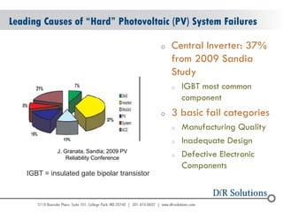
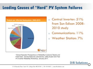
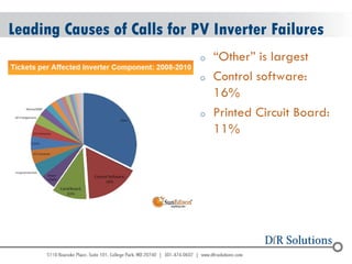
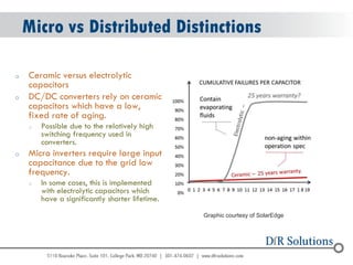
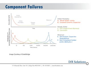
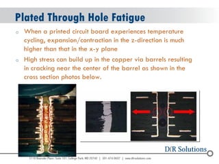
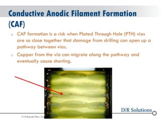
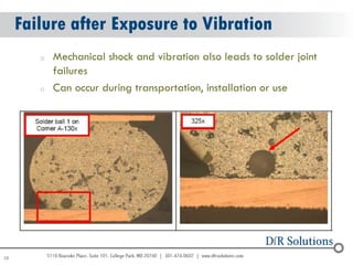
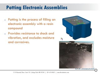
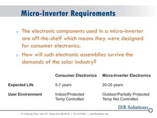
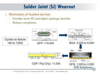
SlideShare a Scribd company logo
© 2004 - 2007 
2010 
– 2010 
Overcoming 25 Year Life Reliability Challenges in Solar Electronics 
DfR Solutions Webinar 
September 27, 2012
© 2004 - 2007 
2010 
Solar Panel “Scams” in the News… 
http://www.bbb.org/blog/2012/06/dont-fall-for-a-solar-paneling-scam-this-summer/
© 2004 - 2007 
2010 
Leading Causes of “Hard” Photovoltaic (PV) System Failures 
oCentral Inverter: 37% from 2009 Sandia Study 
oIGBT most common component 
o3 basic fail categories 
oManufacturing Quality 
oInadequate Design 
oDefective Electronic Components 
J. Granata, Sandia; 2009 PV 
Reliability Conference 
IGBT = insulated gate bipolar transistor
© 2004 - 2007 
2010 
Leading Causes of “Hard” PV System Failures 
oCentral Inverter: 51% from Sun Edison 2008- 2010 study 
oCommunications: 11% 
oWeather Station: 7% 
“Owner/Operator Perspective on Reliability Customer Needs and Field Data”, Sandia National Laboratories, Utility-Scale Grid-Tied PV Inverter Reliability Workshop, January 2011.
© 2004 - 2007 
2010 
Leading Causes of Calls for PV Inverter Failures 
o“Other” is largest 
oControl software: 16% 
oPrinted Circuit Board: 11%
© 2004 - 2007 
2010 
Leading Root Causes of “Hard” PV Inverter Failures 
oParts & Materials: 57% 
oSoftware: 16%
© 2004 - 2007 
2010 
Reliability by Inverter Type
© 2004 - 2007 
2010 
PV System Reliability & Availability 
oEvery alert must be addressed 
oMost software & communication issues can be handled quickly 
oHardware takes longer to resolve 
oPotentially easier to improve availability by focusing on software & communication! 
oTend to be hardware biased!
© 2004 - 2007 
2010 
PV System Failures: Utility Perspective 
oLeading failure causes in US: 
oPoor Design 
oPoor Installation 
oCode Infraction 
oAmbiguous Instructions 
oLack of information and documentation 
oLeading failure causes in developing countries: 
oSelling PV systems to users and financing them privately or by soft loans 
oEncouraged purchase of cheap, poor quality components and minimal maintenance 
oLed to early failures and poor long term sustainability 
Evaluation of the PREP Component : PV 
Systems for Rural Electrification in Kiribati & 
Tuvalu (7 ACP RPR 175) 
DESIGN REVIEW AND APPROVAL OF GRID- TIED PHOTOVOLTAIC SYSTEMS
© 2004 - 2007 
2010 
Inverter Overview 
oInverters perform two key functions 
oConverts the direct current (DC) coming from the panels to the alternating current (AC) used by the electric grid 
oPerform algorithms to maximize the power produced by the system.
© 2004 - 2007 
2010 
Types of PV Inverters 
Graph courtesy of Doron Shmilovitz, Tel Aviv University, Israel
© 2004 - 2007 
2010 
Central Inverters 
oPV modules feed into a central dc-dc converter stage that has: 
oMaximum power point tracking (MPPT) 
oDC-AC inverter to connect to the utility grid. 
oCan’t maximize energy extraction from all modules
© 2004 - 2007 
2010 
Micro-Inverters vs Central Inverters 
oBetter Reliability & Availability 
oLack of single failure point 
oLonger warranty: 15-25 years versus 5-10 years 
oLower DC Voltages, less vulnerable to arcing 
oOptimized Maximum Power Point Tracking (MPPT) per module 
oPV Module level real-time monitoring 
Images courtesy of Paul Parker, SolarBridge
© 2004 - 2007 
2010 
Micro-Inverters 
oThe electronic components used in a micro-inverter are commercial off-the-shelf (COTS) 
oParts designed for consumer electronics but need to survive 25 years in solar installations 
oOutdoor/Partially Protected & Temp Not Controlled
© 2004 - 2007 
2010 
Distributed Inverters 
oSimilar advantages as Micro 
oDesigned to work with power optimizers 
oStandard 10-12 year warranty, some extended to 20-25 years 
oBuilt-in module-level monitoring receiver with communication to internet via broadband or wireless 
oBecause MPPT & voltage management are handled separately for each module by the power optimizer, the inverter is only responsible for DC to AC inversion. So potentially less complicated, expensive & more reliable
© 2004 - 2007 
2010 
Micro vs Distributed Inverters 
oFrom a system reliability and maintainability perspective, both offer advantages over Central inverters. 
oAll inverter types face the same environmental and electronics failure modes. 
oBoth regarded as more cost effective for commercial applications vs utilities 
oBoth add significant software complexity for optimizing and monitoring functions
© 2004 - 2007 
2010 
Micro vs Distributed Distinctions 
oComponent Selection 
oLife limits of Electrolytic Caps versus Ceramic Caps 
oUse of ASICs to reduce discreet parts count 
oDerating 
oPower optimizers are low voltage devices and more easily highly derated 
oEfficiency & Heat Dissipation Differences 
oDistributed/string benefits are true only if designed for the specific optimizer 
oOne company doing this as a complete system 
oNo current standard for DC Optimizers, so other string inverter companies may be hesitant to design a product around a specific vendors’ optimizer.
© 2004 - 2007 
2010 
Micro vs Distributed Distinctions 
oCeramic versus electrolytic capacitors 
oDC/DC converters rely on ceramic capacitors which have a low, fixed rate of aging. 
oPossible due to the relatively high switching frequency used in converters. 
oMicro inverters require large input capacitance due to the grid low frequency. 
oIn some cases, this is implemented with electrolytic capacitors which have a significantly shorter lifetime. 
Graphic courtesy of SolarEdge
© 2004 - 2007 
2010 
Component Failures 
Image Courtesy of SolarBridge
© 2004 - 2007 
2010 
Micro vs Distributed Distinctions 
oASICs allow embedding many electronics into the chip, thereby 
oReduces number of discreet components and potential points of failure. 
oReduced component count on the circuit board also allows manufacturers of power optimizers to decrease the overall size of the product and raise MTBF
© 2004 - 2007 
2010 
Micro vs Distributed Distinctions 
oDerating 
oPower optimizers are low voltage devices and more easily highly derated 
oA lower derating factor may shorten the lifetime of the product due to increased stress under operating conditions.
© 2004 - 2007 
2010 
Micro vs Distributed Distinctions 
oEfficiency & Heat Dissipation Differences 
oMicro-inverters have lower efficiencies than power optimizers. The highest known efficiency of micro- inverter brands is 96%, meaning 4% heat dissipation to the module.
© 2004 - 2007 
2010 
Micro vs Distributed Distinctions 
oDistributed/string benefits are true only if designed for the specific optimizer 
oOne company doing this as a complete system 
oNo current standard for DC Optimizers, so other string inverter companies may be hesitant to design a product around a specific vendors’ optimizer.
© 2004 - 2007 
2010 
Inverter Field Failure Mechanisms 
oSolder joint fatigue failure 
oPlated through hole fatigue failure 
oConductive anodic filament formation (CAF) 
oShock or Vibration (shipping and in use) 
oComponent wear out 
oPotting Induced Failure
© 2004 - 2007 
2010 
oSolder joints “wear out” or fatigue and fail under the long term influence of temperature cycling and mechanical stresses. 
Solder Fatigue
© 2004 - 2007 
2010 
Plated Through Hole Fatigue 
oWhen a printed circuit board experiences temperature cycling, expansion/contraction in the z-direction is much higher than that in the x-y plane 
oHigh stress can build up in the copper via barrels resulting in cracking near the center of the barrel as shown in the cross section photos below.
© 2004 - 2007 
2010 
Conductive Anodic Filament Formation (CAF) 
oCAF formation is a risk when Plated Through Hole (PTH) vias are so close together that damage from drilling can open up a pathway between vias. 
oCopper from the via can migrate along the pathway and eventually cause shorting.
© 2004 - 2007 
2010 
28 
Failure after Exposure to Vibration 
oMechanical shock and vibration also leads to solder joint failures 
oCan occur during transportation, installation or use
© 2004 - 2007 
2010 
Potting Electronic Assemblies 
oPotting is the process of filling an electronic assembly with a resin compound 
oProvides resistance to shock and vibration, and excludes moisture and corrosives.
© 2004 - 2007 
2010 
Printed Circuit Board Warpage due to Potting Shrinkage
© 2004 - 2007 
2010 
oThe use of underfills, potting compounds and thick conformal coatings greatly influences the failure behavior under temperature cycling 
oAny time a material goes through its glass transition (Tg) temperature problems tend to occur 
oUnderfills designed for enhancing shock robustness do not enhance thermal cycling robustness 
oPotting materials can cause PCB warpage and tensile stresses on electronic packages that greatly reduce time to failure 
Potting Rules of Thumb
© 2004 - 2007 
2010 
Some Questions You Should Ask Your Inverter Supplier 
oHow have you evaluated reliability? 
oNot MTBF, certifications or specifications but evaluation under stress conditions to failure 
oWhat is your field failure history & repair rate? 
oWhat fails & why? 
oHow long and how many units in the field? 
oWho installs them? 
oWhat software monitoring options are available?
© 2004 - 2007 
2010 
– 2010 
An Effective Means to Model the Life of Inverter Electronics
© 2004 - 2007 
2010 
Micro-Inverter Requirements 
oThe electronic components used in a micro-inverter are off-the-shelf which means they were designed for consumer electronics. 
oHow will such electronic assemblies survive the demands of the solar industry? 
Consumer Electronics Micro-Inverter Electronics Expected Life 5-7 years 20-25 years User Environment Indoor/Protected Outdoor/Partially Protected Temp Controlled Temp Not Controlled
© 2004 - 2007 
2010 
What can be done? 
oHow can a micro-inverter supplier design the product to meet the requirements AND convince the customer of this? 
oThis talk will discuss a novel new method to model the reliability of an electronic assembly in a variety of conditions based on the design (before building anything). 
oDesign for Reliability (DfR) concepts and Physics of Failure (PoF) are used. . 
oA comprehensive software package was developed to simplify this modeling, thus making it available to design engineers.
© 2004 - 2007 
2010 
Design for Reliability (DfR) 
oDfR: A process for ensuring the reliability of a product or system during the design stage before physical prototype 
oReliability: The measure of a product’s ability to 
o…perform the specified function 
o…at the customer (with their use environment) 
o…over the desired lifetime
© 2004 - 2007 
2010 
DfR & Physics of Failure (PoF) 
oDue to some of the limitations of classic DfR, there has been an increasing interest in PoF (aka, Reliability Physics) – to improve on DfR techniques. 
oPoF Definition: The use of science (physics, chemistry, etc.) to capture an understanding of failure mechanisms and evaluate useful life under actual operating conditions
© 2004 - 2007 
2010 
Micro-Inverter Environment 
oExtreme hot and cold locations (AZ to AK) 
oPossible exposure to moisture/humidity 
oLarge diurnal thermal cycle events (daily) 
oLargest temp swings occur in desert locations where it can reach 64C in the direct sun down to 23C at night (Δ41C)
© 2004 - 2007 
2010 
NREL – Solar Panel Data 
oDiurnal Cycles for Each Month
© 2004 - 2007 
2010 
Possible Inverter Failure Mechanisms 
oSolder joint fatigue failure 
oPlated through hole fatigue failure 
oConductive anodic filament formation (CAF) 
oShock or Vibration (during shipping) 
oComponent wear out.
© 2004 - 2007 
2010 
Is There a Method to Model these Failure Mechanisms? 
oYes 
oAlgorithms exist to estimate the failure rate from solder joint fatigue for different types of components. 
oIPC TR-579 models PTH reliability 
oRisk for CAF can be determined 
oFinite Element Analysis can be used for Shock & Vibration risk. 
oMTBF calculations can be performed to estimate component failure rates.
© 2004 - 2007 
2010 
Leverage in Product Design 
70% of a Product’s Total Cost is Committed by Design 
http://www.ami.ac.uk/courses/topics/0248_dfx/index.html
© 2004 - 200107 
Why is modeling reliability early 
important? 
Architectural Design for Reliability, R. Cranwell and R. Hunter, Sandia Labs, 1997
© 2004 - 2007 
2010 
Earlier is Cheaper 
Reduce Costs by Improving Reliability Upfront
© 2004 - 2007 
2010 
What is the cost impact of poor reliability? 
Aberdeen Group, Printed Circuit Board Design Integrity: The Key to Successful PCB Development, 2007 http://new.marketwire.com/2.0/rel.jsp?id=730231
© 2004 - 2007 
2010 
Solder Joint (SJ) Wearout 
oElimination of leaded devices 
oProvides lower RC and higher package densities 
oReduces compliance 
Cycles to failure -40 to 125C 
QFP: >10,000 
BGA: 3,000 to 8,000 
QFN: 1,000 to 3,000 
CSP / Flip Chip: <1,000
© 2004 - 2007 
2010 
The Newest DfR Tool - Sherlock 
oSherlock – a new tool that models all the circuit card assemblies and provides predicted life curves from many common failure mechanisms. 
oIt is a Semi-Automated CAE knowledge based program 
oThe Semi-Automated Features simplify model creation and analysis 
oEliminates the long, complicated, model creation process and the need for a PhD level expert in PoF, FEA and CFD numerical modeling.
© 2004 - 2007 
2010 
Software Coverage 
oThis software modeling tool predicts failures from 
oSolder joint wear-out from thermal cycling (SAC305 or eutectic SnPb) 
oPlated through hole fatigue 
oConductive anodic filament formation 
o217 MTBF calculations are also generated 
oIn addition the software uses FEA to determine 
oBoard deflection and SJ failure from mechanical vibration 
oThe natural frequencies for the board based on the mount points. 
oBoard deflection due to shock events
© 2004 - 2007 
2010 
oODB files are preferred since they contain all the data necessary for modeling 
oComponent details and placement 
oPCB outline & stack-up 
oDrill hole file with mount points 
oMetal layers, silkscreen, solder mask layers 
Data Import 
Gerber Data can also be imported
© 2004 - 2007 
2010 
PCB Details Required for Modeling
© 2004 - 2007 
2010 
Establish Part Parameters 
oComponents identified along with packaging properties. 
oMinimizes data entry through intelligent parsing and embedded package and material databases
© 2004 - 2007 
2010 
Defining The Durability & Reliability Objectives 
oDefine the Expected Service Life 
oSets The Analysis Range And The Scale For Reliability Over Time Plots 
oLife Cycle Phases 
oShows relative time spent at each phase
© 2004 - 2007 
2010 
Identify Field Environment 
oApproach 1: Use of industry/military specifications 
oMIL-STD-810, 
oMIL-HDBK-310, 
oSAE J1211, 
oIPC-SM-785, 
oTelcordia GR3108, 
oIEC 60721-3, etc. 
oAdvantages 
oSometimes very comprehensive 
oAgreement throughout the industry 
oDisadvantages 
oMost more than 20 years old 
oAlways less or greater than actual (by how much, unknown)
© 2004 - 2007 
2010 
Field Environment (cont.) 
oApproach 2: Based on actual measurements of similar products in similar environments 
oDetermine average and realistic worst-case 
oIdentify all failure-inducing loads 
oInclude all environments 
oManufacturing 
oTransportation 
oStorage 
oField 
Container and Ambient Temperature15.025.035.045.055.065.075.0050100150200250300350400450Hours Temperature (°C) Container Temp (°C) Outdoor Temp (°C)
© 2004 - 2007 
2010 
Input Field (or Test) Environment 
Thermal Cycle Profile 
Vibration Profile 
Shock Profile. 
Handles very complex environments
© 2004 - 2007 
2010 
Thermal Cycle Modeling 
oThe thermal cycle conditions the product will experience can be modeled (Minor’s rule applied for multiple temperatures). 
oPowered components can be assigned an added value above ambient temperature. 
Example of Diurnal TC Conditions in a hot climate
© 2004 - 2007 
2010 
TC Fatigue Analysis – Example Plot
© 2004 - 2007 
2010 
Highest Risk Components 
oLarge Resistors provide the weakest solder joints in this example.
© 2004 - 2007 
2010 
Plated Through-Hole Reliability Modeling 
When a PCB experiences thermal cycling, the expansion/ contraction in the z- direction is much higher than that in the x-y plane. 
The glass fibers constrain the board in the x-y plane but not through the thickness. 
As a result, a great deal of stress can be built up in the copper via barrels resulting in eventual cracking near the center of the barrel as shown in the cross section photos.
© 2004 - 2007 
2010 
PTH Fatigue Results - Example
© 2004 - 2007 
2010 
Combined (SJ & PTH) Lifetime Prediction 
oCombines analysis results into overall failure prediction curve 
PTH 
Solder Joint 
Combined
© 2004 - 2007 
2010 
Risk for Conductive Anodic Filament Formation (CAF) 
oCAF formation becomes a risk when plated through hole vias are so close together that damage from drilling can open up a pathway between vias. 
oCopper from the via can migrate along the pathway and eventually cause shorting.
© 2004 - 2007 
2010 
CAF Analysis 
oThe primary variables that effect the probability of CAF formation are: 
oDistance between vias 
oDamage during drilling process 
oTemperature and humidity conditions 
oVoltage differential between vias 
oThe analysis takes into account the first two variables only (measures distance between all PTH pairs). 
oVias identified as being too close are flagged.
© 2004 - 2007 
2010 
CAF Analysis 
oSoftware will flag vias at high risk for CAF formation
© 2004 - 2007 
2010 
Finite Element Analysis 
oPCBA Example with Mesh Outlined
© 2004 - 2007 
2010 
Natural Frequencies are Calculated 
Select the number of natural frequencies to look for within the desired frequency range. 
Components in high strain regions are at risk. 
•Move the components 
•Move/add mounting points. 
MPs
© 2004 - 2007 
2010 
Vibration Environment 
Complex vibration profiles can be modeled. 
• Qualification test parameters 
• Shipping/Transportation 
• Field conditions
© 2004 - 2007 
2010 
Random Vibration Strain 
Board strain from random vibration is shown (calculated for x, y, and z directions) 
Vibration set to simulate shipping
© 2004 - 2007 
2010 
Vibration Results – Component Breakdown 
Components most at risk for vibration fatigue damage are listed first.
© 2004 - 2007 
2010 
Software Shock 
oImplements Shock based upon a critical board level strain 
oWill not predict how many drops to failure 
oEither the design is robust with regards to the expected shock environment or it is not 
oAdditional work being initiated to investigate corner staking patterns and material influences
© 2004 - 2007 
2010 
Shock Results - Example
© 2004 - 2007 
2010 
Shock Results – Component Breakdown 
Components listed in order of maximum strain experienced.
© 2004 - 2007 
2010 
Constant Failure Rate Module – Components (Mil- HNBK-217F) 
This takes into account the failure rate of the components themselves.
© 2004 - 2007 
2010 
Combined Failure Rate is Provided
© 2004 - 2007 
2010 
Additional Uses for Modeling 
oUse Sherlock to determine thermal cycle test requirements. 
oUse to modify mount point locations 
oUse to determine ESS conditions 
oComponent Replacement 
oDetermine impact of changing to Pb-free solder 
oDetermine expected warranty costs
© 2004 - 2007 
2010 
Warranty Cost Estimate: Example 
•Solder joint fatigue was the dominant wearout mechanism, where the failure rate is predicted ~2% after 20 yrs. 
•Warranty from SJ failure = failure rate * motherboard replacement cost * units sold.
© 2004 - 2007 
2010 
Summary 
oIt is important to eliminate design flaws early in development. 
oMicro-Inverters must survive a challenging environment for long periods of time. 
oA software tool is now available to model the primary failure mechanisms so that inverter electronics can be made more reliable. 
oSherlock modeling will enable a number of “what if” scenarios. 
oChanging package types 
oChanging location of components 
oChanging the mount point locations 
oChanging laminate type, etc. 
oThe software can also be used to determine the TC test conditions that best simulate the field use conditions. 
oMicro-Inverter designs can be built with more confidence that they will survive the challenging environments where they are placed.
© 2004 - 2007 
2010 
Questions 
Thank you for your attention. 
Any questions? 
ctulkoff@dfrsolutions.com 
gcaswell@dfrsolutions.com

More Related Content

What's hot

Selecting a Printed Circuit Board Surface Fnish
Selecting a Printed Circuit Board Surface FnishSelecting a Printed Circuit Board Surface Fnish
Selecting a Printed Circuit Board Surface Fnish
Cheryl Tulkoff
 
Raychem Saudi Arabia Ltd|AKBAR TRADING EST. SAUDI ARABIA| Lv joints TYCO- RA...
Raychem Saudi Arabia Ltd|AKBAR TRADING EST. SAUDI ARABIA| Lv joints  TYCO- RA...Raychem Saudi Arabia Ltd|AKBAR TRADING EST. SAUDI ARABIA| Lv joints  TYCO- RA...
Raychem Saudi Arabia Ltd|AKBAR TRADING EST. SAUDI ARABIA| Lv joints TYCO- RA...
AKBAR TRADING
 
Selecting a Printed Circuit Board Surface Finish
Selecting a Printed Circuit Board Surface FinishSelecting a Printed Circuit Board Surface Finish
Selecting a Printed Circuit Board Surface FinishCheryl Tulkoff
 
Nexans Cable Terminations - Heat Shrink, Cold Shrink, Slip-On
Nexans Cable Terminations - Heat Shrink, Cold Shrink, Slip-OnNexans Cable Terminations - Heat Shrink, Cold Shrink, Slip-On
Nexans Cable Terminations - Heat Shrink, Cold Shrink, Slip-On
Thorne & Derrick International
 
RAYCHEM SAUDI ARABIA LTD. (TYCO ELECTRONICS) |AKBAR TRADING EST. SAUDI ARABIA...
RAYCHEM SAUDI ARABIA LTD. (TYCO ELECTRONICS) |AKBAR TRADING EST. SAUDI ARABIA...RAYCHEM SAUDI ARABIA LTD. (TYCO ELECTRONICS) |AKBAR TRADING EST. SAUDI ARABIA...
RAYCHEM SAUDI ARABIA LTD. (TYCO ELECTRONICS) |AKBAR TRADING EST. SAUDI ARABIA...
AKBAR TRADING
 
ABB Kabeldon - HV High Voltage Cable Joints, Cable Terminations & Separable C...
ABB Kabeldon - HV High Voltage Cable Joints, Cable Terminations & Separable C...ABB Kabeldon - HV High Voltage Cable Joints, Cable Terminations & Separable C...
ABB Kabeldon - HV High Voltage Cable Joints, Cable Terminations & Separable C...
Thorne & Derrick International
 
Surface mounted packages wan007 rev01
Surface mounted packages wan007 rev01Surface mounted packages wan007 rev01
Surface mounted packages wan007 rev01
Dat Tran
 
Alternative Methods for Qualifying EEE Parts for CubeSats
Alternative Methods for Qualifying EEE Parts for CubeSatsAlternative Methods for Qualifying EEE Parts for CubeSats
Alternative Methods for Qualifying EEE Parts for CubeSats
Craig Hillman
 
Reliability of-wearable-electronics
Reliability of-wearable-electronicsReliability of-wearable-electronics
Reliability of-wearable-electronics
Greg Caswell
 
Wearable Electronics and Reliability
Wearable Electronics and ReliabilityWearable Electronics and Reliability
Wearable Electronics and Reliability
Craig Hillman
 
Raychem saudi arabia ltd. high voltage , medium voltage &amp; low voltage cab...
Raychem saudi arabia ltd. high voltage , medium voltage &amp; low voltage cab...Raychem saudi arabia ltd. high voltage , medium voltage &amp; low voltage cab...
Raychem saudi arabia ltd. high voltage , medium voltage &amp; low voltage cab...
AKBAR TRADING
 
Cable Mgr cable tray Introduction
Cable Mgr cable tray Introduction Cable Mgr cable tray Introduction
Cable Mgr cable tray Introduction
Gabriel Vasquez
 
EPP-0843-10/11 RAYCHEM JOINT KIT | AKBAR TRADING EST. SAUDI ARABIA|
EPP-0843-10/11 RAYCHEM JOINT KIT | AKBAR TRADING EST. SAUDI ARABIA|EPP-0843-10/11 RAYCHEM JOINT KIT | AKBAR TRADING EST. SAUDI ARABIA|
EPP-0843-10/11 RAYCHEM JOINT KIT | AKBAR TRADING EST. SAUDI ARABIA|
AKBAR TRADING
 
Elastimold - Cable Connectors, Joints, Terminations Catalogue
Elastimold - Cable Connectors, Joints, Terminations CatalogueElastimold - Cable Connectors, Joints, Terminations Catalogue
Elastimold - Cable Connectors, Joints, Terminations Catalogue
Thorne & Derrick International
 
Raychem inline joints for plastic and rubber insulated cables up to 1 kV
Raychem inline joints for plastic and rubber insulated cables up to 1 kVRaychem inline joints for plastic and rubber insulated cables up to 1 kV
Raychem inline joints for plastic and rubber insulated cables up to 1 kV
AKBAR TRADING
 
State of the art of stator winding supports in slot area and winding overhang...
State of the art of stator winding supports in slot area and winding overhang...State of the art of stator winding supports in slot area and winding overhang...
State of the art of stator winding supports in slot area and winding overhang...
Power System Operation
 
Raychem EAKT-1659 | AKBAR TRADING EST| mail@akbartrading.com
Raychem EAKT-1659 | AKBAR TRADING EST| mail@akbartrading.comRaychem EAKT-1659 | AKBAR TRADING EST| mail@akbartrading.com
Raychem EAKT-1659 | AKBAR TRADING EST| mail@akbartrading.com
AKBAR TRADING
 
Elastimold Shrink Fit High Voltage Cable Joints
Elastimold Shrink Fit High Voltage Cable JointsElastimold Shrink Fit High Voltage Cable Joints
Elastimold Shrink Fit High Voltage Cable Joints
Thorne & Derrick International
 
Raychem Heat Shrink - Raychem Tyco Heat Shrink Tubing And Sleeving
Raychem Heat Shrink - Raychem Tyco Heat Shrink Tubing And SleevingRaychem Heat Shrink - Raychem Tyco Heat Shrink Tubing And Sleeving
Raychem Heat Shrink - Raychem Tyco Heat Shrink Tubing And Sleeving
Thorne & Derrick International
 
REDCATT TECH PAPER== Speaker Transducer Dome bonding
REDCATT TECH PAPER== Speaker Transducer Dome bondingREDCATT TECH PAPER== Speaker Transducer Dome bonding
REDCATT TECH PAPER== Speaker Transducer Dome bonding
HTCS LLC
 

What's hot (20)

Selecting a Printed Circuit Board Surface Fnish
Selecting a Printed Circuit Board Surface FnishSelecting a Printed Circuit Board Surface Fnish
Selecting a Printed Circuit Board Surface Fnish
 
Raychem Saudi Arabia Ltd|AKBAR TRADING EST. SAUDI ARABIA| Lv joints TYCO- RA...
Raychem Saudi Arabia Ltd|AKBAR TRADING EST. SAUDI ARABIA| Lv joints  TYCO- RA...Raychem Saudi Arabia Ltd|AKBAR TRADING EST. SAUDI ARABIA| Lv joints  TYCO- RA...
Raychem Saudi Arabia Ltd|AKBAR TRADING EST. SAUDI ARABIA| Lv joints TYCO- RA...
 
Selecting a Printed Circuit Board Surface Finish
Selecting a Printed Circuit Board Surface FinishSelecting a Printed Circuit Board Surface Finish
Selecting a Printed Circuit Board Surface Finish
 
Nexans Cable Terminations - Heat Shrink, Cold Shrink, Slip-On
Nexans Cable Terminations - Heat Shrink, Cold Shrink, Slip-OnNexans Cable Terminations - Heat Shrink, Cold Shrink, Slip-On
Nexans Cable Terminations - Heat Shrink, Cold Shrink, Slip-On
 
RAYCHEM SAUDI ARABIA LTD. (TYCO ELECTRONICS) |AKBAR TRADING EST. SAUDI ARABIA...
RAYCHEM SAUDI ARABIA LTD. (TYCO ELECTRONICS) |AKBAR TRADING EST. SAUDI ARABIA...RAYCHEM SAUDI ARABIA LTD. (TYCO ELECTRONICS) |AKBAR TRADING EST. SAUDI ARABIA...
RAYCHEM SAUDI ARABIA LTD. (TYCO ELECTRONICS) |AKBAR TRADING EST. SAUDI ARABIA...
 
ABB Kabeldon - HV High Voltage Cable Joints, Cable Terminations & Separable C...
ABB Kabeldon - HV High Voltage Cable Joints, Cable Terminations & Separable C...ABB Kabeldon - HV High Voltage Cable Joints, Cable Terminations & Separable C...
ABB Kabeldon - HV High Voltage Cable Joints, Cable Terminations & Separable C...
 
Surface mounted packages wan007 rev01
Surface mounted packages wan007 rev01Surface mounted packages wan007 rev01
Surface mounted packages wan007 rev01
 
Alternative Methods for Qualifying EEE Parts for CubeSats
Alternative Methods for Qualifying EEE Parts for CubeSatsAlternative Methods for Qualifying EEE Parts for CubeSats
Alternative Methods for Qualifying EEE Parts for CubeSats
 
Reliability of-wearable-electronics
Reliability of-wearable-electronicsReliability of-wearable-electronics
Reliability of-wearable-electronics
 
Wearable Electronics and Reliability
Wearable Electronics and ReliabilityWearable Electronics and Reliability
Wearable Electronics and Reliability
 
Raychem saudi arabia ltd. high voltage , medium voltage &amp; low voltage cab...
Raychem saudi arabia ltd. high voltage , medium voltage &amp; low voltage cab...Raychem saudi arabia ltd. high voltage , medium voltage &amp; low voltage cab...
Raychem saudi arabia ltd. high voltage , medium voltage &amp; low voltage cab...
 
Cable Mgr cable tray Introduction
Cable Mgr cable tray Introduction Cable Mgr cable tray Introduction
Cable Mgr cable tray Introduction
 
EPP-0843-10/11 RAYCHEM JOINT KIT | AKBAR TRADING EST. SAUDI ARABIA|
EPP-0843-10/11 RAYCHEM JOINT KIT | AKBAR TRADING EST. SAUDI ARABIA|EPP-0843-10/11 RAYCHEM JOINT KIT | AKBAR TRADING EST. SAUDI ARABIA|
EPP-0843-10/11 RAYCHEM JOINT KIT | AKBAR TRADING EST. SAUDI ARABIA|
 
Elastimold - Cable Connectors, Joints, Terminations Catalogue
Elastimold - Cable Connectors, Joints, Terminations CatalogueElastimold - Cable Connectors, Joints, Terminations Catalogue
Elastimold - Cable Connectors, Joints, Terminations Catalogue
 
Raychem inline joints for plastic and rubber insulated cables up to 1 kV
Raychem inline joints for plastic and rubber insulated cables up to 1 kVRaychem inline joints for plastic and rubber insulated cables up to 1 kV
Raychem inline joints for plastic and rubber insulated cables up to 1 kV
 
State of the art of stator winding supports in slot area and winding overhang...
State of the art of stator winding supports in slot area and winding overhang...State of the art of stator winding supports in slot area and winding overhang...
State of the art of stator winding supports in slot area and winding overhang...
 
Raychem EAKT-1659 | AKBAR TRADING EST| mail@akbartrading.com
Raychem EAKT-1659 | AKBAR TRADING EST| mail@akbartrading.comRaychem EAKT-1659 | AKBAR TRADING EST| mail@akbartrading.com
Raychem EAKT-1659 | AKBAR TRADING EST| mail@akbartrading.com
 
Elastimold Shrink Fit High Voltage Cable Joints
Elastimold Shrink Fit High Voltage Cable JointsElastimold Shrink Fit High Voltage Cable Joints
Elastimold Shrink Fit High Voltage Cable Joints
 
Raychem Heat Shrink - Raychem Tyco Heat Shrink Tubing And Sleeving
Raychem Heat Shrink - Raychem Tyco Heat Shrink Tubing And SleevingRaychem Heat Shrink - Raychem Tyco Heat Shrink Tubing And Sleeving
Raychem Heat Shrink - Raychem Tyco Heat Shrink Tubing And Sleeving
 
REDCATT TECH PAPER== Speaker Transducer Dome bonding
REDCATT TECH PAPER== Speaker Transducer Dome bondingREDCATT TECH PAPER== Speaker Transducer Dome bonding
REDCATT TECH PAPER== Speaker Transducer Dome bonding
 

Similar to Overcoming 25 year life reliability challenges in solar electronics

Automating lifetime simulation of power PCBs
Automating lifetime simulation of power PCBsAutomating lifetime simulation of power PCBs
Automating lifetime simulation of power PCBs
Greg Caswell
 
Advances in Ceramic Capacitors
Advances in Ceramic CapacitorsAdvances in Ceramic Capacitors
Advances in Ceramic Capacitors
Randall Ghany
 
Advances in Ceramic Capacitors
Advances in Ceramic CapacitorsAdvances in Ceramic Capacitors
Advances in Ceramic Capacitors
KEMET Electronics Corporation
 
IRJET- Current Limiting Transformer
IRJET-  	  Current Limiting TransformerIRJET-  	  Current Limiting Transformer
IRJET- Current Limiting Transformer
IRJET Journal
 
The Solar Future DE - Christoph von Bergen "What is the market and technology...
The Solar Future DE - Christoph von Bergen "What is the market and technology...The Solar Future DE - Christoph von Bergen "What is the market and technology...
The Solar Future DE - Christoph von Bergen "What is the market and technology...
Paul van der Linden
 
Presentation Smart Hospital Projects and JMV LPS Ltd
 Presentation  Smart Hospital Projects  and JMV LPS Ltd Presentation  Smart Hospital Projects  and JMV LPS Ltd
Presentation Smart Hospital Projects and JMV LPS Ltd
Mahesh Chandra Manav
 
Jmv presentation smart hospital projects india-1
Jmv  presentation  smart hospital projects india-1Jmv  presentation  smart hospital projects india-1
Jmv presentation smart hospital projects india-1
Mahesh Chandra Manav
 
BME C0G Ceramic DC Link Evaluation
BME C0G Ceramic DC Link EvaluationBME C0G Ceramic DC Link Evaluation
BME C0G Ceramic DC Link Evaluation
KEMET Electronics Corporation
 
IRJET- Embedded System based Multi-Source Leakage Current Protection for Low ...
IRJET- Embedded System based Multi-Source Leakage Current Protection for Low ...IRJET- Embedded System based Multi-Source Leakage Current Protection for Low ...
IRJET- Embedded System based Multi-Source Leakage Current Protection for Low ...
IRJET Journal
 
OVER-CURRENT RELAYS IN VOLTAGE DISTRIBUTION
OVER-CURRENT RELAYS IN VOLTAGE DISTRIBUTIONOVER-CURRENT RELAYS IN VOLTAGE DISTRIBUTION
OVER-CURRENT RELAYS IN VOLTAGE DISTRIBUTION
IRJET Journal
 
IRJET- Multi-Level Inverter for Solar On-Grid System Design
IRJET- Multi-Level Inverter for Solar On-Grid System DesignIRJET- Multi-Level Inverter for Solar On-Grid System Design
IRJET- Multi-Level Inverter for Solar On-Grid System Design
IRJET Journal
 
Catalog máy biến áp Lerand ( Cast Resin Transformers )
Catalog máy biến áp Lerand ( Cast Resin Transformers )Catalog máy biến áp Lerand ( Cast Resin Transformers )
Catalog máy biến áp Lerand ( Cast Resin Transformers )
CTY TNHH HẠO PHƯƠNG
 
Underground Cable Fault Detection Using IOT
Underground Cable Fault Detection Using IOTUnderground Cable Fault Detection Using IOT
Underground Cable Fault Detection Using IOT
IRJET Journal
 
Catalog ls susol mc_leaflet_e_0901
Catalog ls susol mc_leaflet_e_0901Catalog ls susol mc_leaflet_e_0901
Catalog ls susol mc_leaflet_e_0901
Dien Ha The
 
Catalog ls susol mc_leaflet_e_0901_dienhathe.vn
Catalog ls susol mc_leaflet_e_0901_dienhathe.vnCatalog ls susol mc_leaflet_e_0901_dienhathe.vn
Catalog ls susol mc_leaflet_e_0901_dienhathe.vn
Dien Ha The
 
Snap-In High Vibration Products: AEC-Q200 Automotive for High Voltage Perform...
Snap-In High Vibration Products: AEC-Q200 Automotive for High Voltage Perform...Snap-In High Vibration Products: AEC-Q200 Automotive for High Voltage Perform...
Snap-In High Vibration Products: AEC-Q200 Automotive for High Voltage Perform...
KEMET Electronics Corporation
 
AEC-Q200 Automotive for High Voltage Performance Requirements
AEC-Q200 Automotive for High Voltage Performance RequirementsAEC-Q200 Automotive for High Voltage Performance Requirements
AEC-Q200 Automotive for High Voltage Performance Requirements
KEMET Electronics Corporation
 
Littelfuse Solutions: Industrial Motor Drives and Soft Starters
Littelfuse Solutions: Industrial Motor Drives and Soft StartersLittelfuse Solutions: Industrial Motor Drives and Soft Starters
Littelfuse Solutions: Industrial Motor Drives and Soft Starters
Littelfuse
 
IRJET- Rogowiski Coil
IRJET- Rogowiski CoilIRJET- Rogowiski Coil
IRJET- Rogowiski Coil
IRJET Journal
 
Presentation lightning protection system by jmv lps
Presentation lightning protection system by jmv lpsPresentation lightning protection system by jmv lps
Presentation lightning protection system by jmv lps
Mahesh Chandra Manav
 

Similar to Overcoming 25 year life reliability challenges in solar electronics (20)

Automating lifetime simulation of power PCBs
Automating lifetime simulation of power PCBsAutomating lifetime simulation of power PCBs
Automating lifetime simulation of power PCBs
 
Advances in Ceramic Capacitors
Advances in Ceramic CapacitorsAdvances in Ceramic Capacitors
Advances in Ceramic Capacitors
 
Advances in Ceramic Capacitors
Advances in Ceramic CapacitorsAdvances in Ceramic Capacitors
Advances in Ceramic Capacitors
 
IRJET- Current Limiting Transformer
IRJET-  	  Current Limiting TransformerIRJET-  	  Current Limiting Transformer
IRJET- Current Limiting Transformer
 
The Solar Future DE - Christoph von Bergen "What is the market and technology...
The Solar Future DE - Christoph von Bergen "What is the market and technology...The Solar Future DE - Christoph von Bergen "What is the market and technology...
The Solar Future DE - Christoph von Bergen "What is the market and technology...
 
Presentation Smart Hospital Projects and JMV LPS Ltd
 Presentation  Smart Hospital Projects  and JMV LPS Ltd Presentation  Smart Hospital Projects  and JMV LPS Ltd
Presentation Smart Hospital Projects and JMV LPS Ltd
 
Jmv presentation smart hospital projects india-1
Jmv  presentation  smart hospital projects india-1Jmv  presentation  smart hospital projects india-1
Jmv presentation smart hospital projects india-1
 
BME C0G Ceramic DC Link Evaluation
BME C0G Ceramic DC Link EvaluationBME C0G Ceramic DC Link Evaluation
BME C0G Ceramic DC Link Evaluation
 
IRJET- Embedded System based Multi-Source Leakage Current Protection for Low ...
IRJET- Embedded System based Multi-Source Leakage Current Protection for Low ...IRJET- Embedded System based Multi-Source Leakage Current Protection for Low ...
IRJET- Embedded System based Multi-Source Leakage Current Protection for Low ...
 
OVER-CURRENT RELAYS IN VOLTAGE DISTRIBUTION
OVER-CURRENT RELAYS IN VOLTAGE DISTRIBUTIONOVER-CURRENT RELAYS IN VOLTAGE DISTRIBUTION
OVER-CURRENT RELAYS IN VOLTAGE DISTRIBUTION
 
IRJET- Multi-Level Inverter for Solar On-Grid System Design
IRJET- Multi-Level Inverter for Solar On-Grid System DesignIRJET- Multi-Level Inverter for Solar On-Grid System Design
IRJET- Multi-Level Inverter for Solar On-Grid System Design
 
Catalog máy biến áp Lerand ( Cast Resin Transformers )
Catalog máy biến áp Lerand ( Cast Resin Transformers )Catalog máy biến áp Lerand ( Cast Resin Transformers )
Catalog máy biến áp Lerand ( Cast Resin Transformers )
 
Underground Cable Fault Detection Using IOT
Underground Cable Fault Detection Using IOTUnderground Cable Fault Detection Using IOT
Underground Cable Fault Detection Using IOT
 
Catalog ls susol mc_leaflet_e_0901
Catalog ls susol mc_leaflet_e_0901Catalog ls susol mc_leaflet_e_0901
Catalog ls susol mc_leaflet_e_0901
 
Catalog ls susol mc_leaflet_e_0901_dienhathe.vn
Catalog ls susol mc_leaflet_e_0901_dienhathe.vnCatalog ls susol mc_leaflet_e_0901_dienhathe.vn
Catalog ls susol mc_leaflet_e_0901_dienhathe.vn
 
Snap-In High Vibration Products: AEC-Q200 Automotive for High Voltage Perform...
Snap-In High Vibration Products: AEC-Q200 Automotive for High Voltage Perform...Snap-In High Vibration Products: AEC-Q200 Automotive for High Voltage Perform...
Snap-In High Vibration Products: AEC-Q200 Automotive for High Voltage Perform...
 
AEC-Q200 Automotive for High Voltage Performance Requirements
AEC-Q200 Automotive for High Voltage Performance RequirementsAEC-Q200 Automotive for High Voltage Performance Requirements
AEC-Q200 Automotive for High Voltage Performance Requirements
 
Littelfuse Solutions: Industrial Motor Drives and Soft Starters
Littelfuse Solutions: Industrial Motor Drives and Soft StartersLittelfuse Solutions: Industrial Motor Drives and Soft Starters
Littelfuse Solutions: Industrial Motor Drives and Soft Starters
 
IRJET- Rogowiski Coil
IRJET- Rogowiski CoilIRJET- Rogowiski Coil
IRJET- Rogowiski Coil
 
Presentation lightning protection system by jmv lps
Presentation lightning protection system by jmv lpsPresentation lightning protection system by jmv lps
Presentation lightning protection system by jmv lps
 

More from Greg Caswell

Understanding the-criticality-of-stencil-aperture-design-and-implementation-f...
Understanding the-criticality-of-stencil-aperture-design-and-implementation-f...Understanding the-criticality-of-stencil-aperture-design-and-implementation-f...
Understanding the-criticality-of-stencil-aperture-design-and-implementation-f...
Greg Caswell
 
Reliability Modeling of Electronics for Co-designed Systems
Reliability Modeling of Electronics for Co-designed SystemsReliability Modeling of Electronics for Co-designed Systems
Reliability Modeling of Electronics for Co-designed Systems
Greg Caswell
 
Predicting Reliability of Zero Level Through Silicon Vias (TSV)
Predicting Reliability of Zero Level Through Silicon Vias (TSV)Predicting Reliability of Zero Level Through Silicon Vias (TSV)
Predicting Reliability of Zero Level Through Silicon Vias (TSV)
Greg Caswell
 
Ensuring and predicting the reliability of cpv
Ensuring and predicting the reliability of cpvEnsuring and predicting the reliability of cpv
Ensuring and predicting the reliability of cpv
Greg Caswell
 
DfR Advanced Packaging
DfR Advanced PackagingDfR Advanced Packaging
DfR Advanced Packaging
Greg Caswell
 
Counterfeit prevention & detection strategies, how to do it, when to do it.
Counterfeit prevention & detection strategies, how to do it, when to do it.Counterfeit prevention & detection strategies, how to do it, when to do it.
Counterfeit prevention & detection strategies, how to do it, when to do it.
Greg Caswell
 
Bga reballing from pb free to sn pb metallurgy
Bga reballing from pb free to sn pb metallurgyBga reballing from pb free to sn pb metallurgy
Bga reballing from pb free to sn pb metallurgy
Greg Caswell
 
A solder joint reliability model for the philips lumileds luxeon rebel led c...
A solder joint reliability model for the philips lumileds luxeon rebel led  c...A solder joint reliability model for the philips lumileds luxeon rebel led  c...
A solder joint reliability model for the philips lumileds luxeon rebel led c...
Greg Caswell
 
Part quality-presentation-how-to-test-when-what-it-all-means
Part quality-presentation-how-to-test-when-what-it-all-meansPart quality-presentation-how-to-test-when-what-it-all-means
Part quality-presentation-how-to-test-when-what-it-all-means
Greg Caswell
 
.3mm CSP and LFCSP Reliability
.3mm CSP and LFCSP Reliability.3mm CSP and LFCSP Reliability
.3mm CSP and LFCSP Reliability
Greg Caswell
 
Non functional-pads-should-they-stay-or-should-they-go
Non functional-pads-should-they-stay-or-should-they-goNon functional-pads-should-they-stay-or-should-they-go
Non functional-pads-should-they-stay-or-should-they-go
Greg Caswell
 

More from Greg Caswell (11)

Understanding the-criticality-of-stencil-aperture-design-and-implementation-f...
Understanding the-criticality-of-stencil-aperture-design-and-implementation-f...Understanding the-criticality-of-stencil-aperture-design-and-implementation-f...
Understanding the-criticality-of-stencil-aperture-design-and-implementation-f...
 
Reliability Modeling of Electronics for Co-designed Systems
Reliability Modeling of Electronics for Co-designed SystemsReliability Modeling of Electronics for Co-designed Systems
Reliability Modeling of Electronics for Co-designed Systems
 
Predicting Reliability of Zero Level Through Silicon Vias (TSV)
Predicting Reliability of Zero Level Through Silicon Vias (TSV)Predicting Reliability of Zero Level Through Silicon Vias (TSV)
Predicting Reliability of Zero Level Through Silicon Vias (TSV)
 
Ensuring and predicting the reliability of cpv
Ensuring and predicting the reliability of cpvEnsuring and predicting the reliability of cpv
Ensuring and predicting the reliability of cpv
 
DfR Advanced Packaging
DfR Advanced PackagingDfR Advanced Packaging
DfR Advanced Packaging
 
Counterfeit prevention & detection strategies, how to do it, when to do it.
Counterfeit prevention & detection strategies, how to do it, when to do it.Counterfeit prevention & detection strategies, how to do it, when to do it.
Counterfeit prevention & detection strategies, how to do it, when to do it.
 
Bga reballing from pb free to sn pb metallurgy
Bga reballing from pb free to sn pb metallurgyBga reballing from pb free to sn pb metallurgy
Bga reballing from pb free to sn pb metallurgy
 
A solder joint reliability model for the philips lumileds luxeon rebel led c...
A solder joint reliability model for the philips lumileds luxeon rebel led  c...A solder joint reliability model for the philips lumileds luxeon rebel led  c...
A solder joint reliability model for the philips lumileds luxeon rebel led c...
 
Part quality-presentation-how-to-test-when-what-it-all-means
Part quality-presentation-how-to-test-when-what-it-all-meansPart quality-presentation-how-to-test-when-what-it-all-means
Part quality-presentation-how-to-test-when-what-it-all-means
 
.3mm CSP and LFCSP Reliability
.3mm CSP and LFCSP Reliability.3mm CSP and LFCSP Reliability
.3mm CSP and LFCSP Reliability
 
Non functional-pads-should-they-stay-or-should-they-go
Non functional-pads-should-they-stay-or-should-they-goNon functional-pads-should-they-stay-or-should-they-go
Non functional-pads-should-they-stay-or-should-they-go
 

Recently uploaded

LIGA(E)11111111111111111111111111111111111111111.ppt
LIGA(E)11111111111111111111111111111111111111111.pptLIGA(E)11111111111111111111111111111111111111111.ppt
LIGA(E)11111111111111111111111111111111111111111.ppt
ssuser9bd3ba
 
在线办理(ANU毕业证书)澳洲国立大学毕业证录取通知书一模一样
在线办理(ANU毕业证书)澳洲国立大学毕业证录取通知书一模一样在线办理(ANU毕业证书)澳洲国立大学毕业证录取通知书一模一样
在线办理(ANU毕业证书)澳洲国立大学毕业证录取通知书一模一样
obonagu
 
Top 10 Oil and Gas Projects in Saudi Arabia 2024.pdf
Top 10 Oil and Gas Projects in Saudi Arabia 2024.pdfTop 10 Oil and Gas Projects in Saudi Arabia 2024.pdf
Top 10 Oil and Gas Projects in Saudi Arabia 2024.pdf
Teleport Manpower Consultant
 
weather web application report.pdf
weather web application report.pdfweather web application report.pdf
weather web application report.pdf
Pratik Pawar
 
Halogenation process of chemical process industries
Halogenation process of chemical process industriesHalogenation process of chemical process industries
Halogenation process of chemical process industries
MuhammadTufail242431
 
ethical hacking-mobile hacking methods.ppt
ethical hacking-mobile hacking methods.pptethical hacking-mobile hacking methods.ppt
ethical hacking-mobile hacking methods.ppt
Jayaprasanna4
 
ethical hacking in wireless-hacking1.ppt
ethical hacking in wireless-hacking1.pptethical hacking in wireless-hacking1.ppt
ethical hacking in wireless-hacking1.ppt
Jayaprasanna4
 
Design and Analysis of Algorithms-DP,Backtracking,Graphs,B&B
Design and Analysis of Algorithms-DP,Backtracking,Graphs,B&BDesign and Analysis of Algorithms-DP,Backtracking,Graphs,B&B
Design and Analysis of Algorithms-DP,Backtracking,Graphs,B&B
Sreedhar Chowdam
 
MCQ Soil mechanics questions (Soil shear strength).pdf
MCQ Soil mechanics questions (Soil shear strength).pdfMCQ Soil mechanics questions (Soil shear strength).pdf
MCQ Soil mechanics questions (Soil shear strength).pdf
Osamah Alsalih
 
The role of big data in decision making.
The role of big data in decision making.The role of big data in decision making.
The role of big data in decision making.
ankuprajapati0525
 
Standard Reomte Control Interface - Neometrix
Standard Reomte Control Interface - NeometrixStandard Reomte Control Interface - Neometrix
Standard Reomte Control Interface - Neometrix
Neometrix_Engineering_Pvt_Ltd
 
Water Industry Process Automation and Control Monthly - May 2024.pdf
Water Industry Process Automation and Control Monthly - May 2024.pdfWater Industry Process Automation and Control Monthly - May 2024.pdf
Water Industry Process Automation and Control Monthly - May 2024.pdf
Water Industry Process Automation & Control
 
power quality voltage fluctuation UNIT - I.pptx
power quality voltage fluctuation UNIT - I.pptxpower quality voltage fluctuation UNIT - I.pptx
power quality voltage fluctuation UNIT - I.pptx
ViniHema
 
Student information management system project report ii.pdf
Student information management system project report ii.pdfStudent information management system project report ii.pdf
Student information management system project report ii.pdf
Kamal Acharya
 
Forklift Classes Overview by Intella Parts
Forklift Classes Overview by Intella PartsForklift Classes Overview by Intella Parts
Forklift Classes Overview by Intella Parts
Intella Parts
 
WATER CRISIS and its solutions-pptx 1234
WATER CRISIS and its solutions-pptx 1234WATER CRISIS and its solutions-pptx 1234
WATER CRISIS and its solutions-pptx 1234
AafreenAbuthahir2
 
Final project report on grocery store management system..pdf
Final project report on grocery store management system..pdfFinal project report on grocery store management system..pdf
Final project report on grocery store management system..pdf
Kamal Acharya
 
Railway Signalling Principles Edition 3.pdf
Railway Signalling Principles Edition 3.pdfRailway Signalling Principles Edition 3.pdf
Railway Signalling Principles Edition 3.pdf
TeeVichai
 
TECHNICAL TRAINING MANUAL GENERAL FAMILIARIZATION COURSE
TECHNICAL TRAINING MANUAL   GENERAL FAMILIARIZATION COURSETECHNICAL TRAINING MANUAL   GENERAL FAMILIARIZATION COURSE
TECHNICAL TRAINING MANUAL GENERAL FAMILIARIZATION COURSE
DuvanRamosGarzon1
 
Hybrid optimization of pumped hydro system and solar- Engr. Abdul-Azeez.pdf
Hybrid optimization of pumped hydro system and solar- Engr. Abdul-Azeez.pdfHybrid optimization of pumped hydro system and solar- Engr. Abdul-Azeez.pdf
Hybrid optimization of pumped hydro system and solar- Engr. Abdul-Azeez.pdf
fxintegritypublishin
 

Recently uploaded (20)

LIGA(E)11111111111111111111111111111111111111111.ppt
LIGA(E)11111111111111111111111111111111111111111.pptLIGA(E)11111111111111111111111111111111111111111.ppt
LIGA(E)11111111111111111111111111111111111111111.ppt
 
在线办理(ANU毕业证书)澳洲国立大学毕业证录取通知书一模一样
在线办理(ANU毕业证书)澳洲国立大学毕业证录取通知书一模一样在线办理(ANU毕业证书)澳洲国立大学毕业证录取通知书一模一样
在线办理(ANU毕业证书)澳洲国立大学毕业证录取通知书一模一样
 
Top 10 Oil and Gas Projects in Saudi Arabia 2024.pdf
Top 10 Oil and Gas Projects in Saudi Arabia 2024.pdfTop 10 Oil and Gas Projects in Saudi Arabia 2024.pdf
Top 10 Oil and Gas Projects in Saudi Arabia 2024.pdf
 
weather web application report.pdf
weather web application report.pdfweather web application report.pdf
weather web application report.pdf
 
Halogenation process of chemical process industries
Halogenation process of chemical process industriesHalogenation process of chemical process industries
Halogenation process of chemical process industries
 
ethical hacking-mobile hacking methods.ppt
ethical hacking-mobile hacking methods.pptethical hacking-mobile hacking methods.ppt
ethical hacking-mobile hacking methods.ppt
 
ethical hacking in wireless-hacking1.ppt
ethical hacking in wireless-hacking1.pptethical hacking in wireless-hacking1.ppt
ethical hacking in wireless-hacking1.ppt
 
Design and Analysis of Algorithms-DP,Backtracking,Graphs,B&B
Design and Analysis of Algorithms-DP,Backtracking,Graphs,B&BDesign and Analysis of Algorithms-DP,Backtracking,Graphs,B&B
Design and Analysis of Algorithms-DP,Backtracking,Graphs,B&B
 
MCQ Soil mechanics questions (Soil shear strength).pdf
MCQ Soil mechanics questions (Soil shear strength).pdfMCQ Soil mechanics questions (Soil shear strength).pdf
MCQ Soil mechanics questions (Soil shear strength).pdf
 
The role of big data in decision making.
The role of big data in decision making.The role of big data in decision making.
The role of big data in decision making.
 
Standard Reomte Control Interface - Neometrix
Standard Reomte Control Interface - NeometrixStandard Reomte Control Interface - Neometrix
Standard Reomte Control Interface - Neometrix
 
Water Industry Process Automation and Control Monthly - May 2024.pdf
Water Industry Process Automation and Control Monthly - May 2024.pdfWater Industry Process Automation and Control Monthly - May 2024.pdf
Water Industry Process Automation and Control Monthly - May 2024.pdf
 
power quality voltage fluctuation UNIT - I.pptx
power quality voltage fluctuation UNIT - I.pptxpower quality voltage fluctuation UNIT - I.pptx
power quality voltage fluctuation UNIT - I.pptx
 
Student information management system project report ii.pdf
Student information management system project report ii.pdfStudent information management system project report ii.pdf
Student information management system project report ii.pdf
 
Forklift Classes Overview by Intella Parts
Forklift Classes Overview by Intella PartsForklift Classes Overview by Intella Parts
Forklift Classes Overview by Intella Parts
 
WATER CRISIS and its solutions-pptx 1234
WATER CRISIS and its solutions-pptx 1234WATER CRISIS and its solutions-pptx 1234
WATER CRISIS and its solutions-pptx 1234
 
Final project report on grocery store management system..pdf
Final project report on grocery store management system..pdfFinal project report on grocery store management system..pdf
Final project report on grocery store management system..pdf
 
Railway Signalling Principles Edition 3.pdf
Railway Signalling Principles Edition 3.pdfRailway Signalling Principles Edition 3.pdf
Railway Signalling Principles Edition 3.pdf
 
TECHNICAL TRAINING MANUAL GENERAL FAMILIARIZATION COURSE
TECHNICAL TRAINING MANUAL   GENERAL FAMILIARIZATION COURSETECHNICAL TRAINING MANUAL   GENERAL FAMILIARIZATION COURSE
TECHNICAL TRAINING MANUAL GENERAL FAMILIARIZATION COURSE
 
Hybrid optimization of pumped hydro system and solar- Engr. Abdul-Azeez.pdf
Hybrid optimization of pumped hydro system and solar- Engr. Abdul-Azeez.pdfHybrid optimization of pumped hydro system and solar- Engr. Abdul-Azeez.pdf
Hybrid optimization of pumped hydro system and solar- Engr. Abdul-Azeez.pdf
 

Overcoming 25 year life reliability challenges in solar electronics

  • 1. © 2004 - 2007 2010 – 2010 Overcoming 25 Year Life Reliability Challenges in Solar Electronics DfR Solutions Webinar September 27, 2012
  • 2. © 2004 - 2007 2010 Solar Panel “Scams” in the News… http://www.bbb.org/blog/2012/06/dont-fall-for-a-solar-paneling-scam-this-summer/
  • 3. © 2004 - 2007 2010 Leading Causes of “Hard” Photovoltaic (PV) System Failures oCentral Inverter: 37% from 2009 Sandia Study oIGBT most common component o3 basic fail categories oManufacturing Quality oInadequate Design oDefective Electronic Components J. Granata, Sandia; 2009 PV Reliability Conference IGBT = insulated gate bipolar transistor
  • 4. © 2004 - 2007 2010 Leading Causes of “Hard” PV System Failures oCentral Inverter: 51% from Sun Edison 2008- 2010 study oCommunications: 11% oWeather Station: 7% “Owner/Operator Perspective on Reliability Customer Needs and Field Data”, Sandia National Laboratories, Utility-Scale Grid-Tied PV Inverter Reliability Workshop, January 2011.
  • 5. © 2004 - 2007 2010 Leading Causes of Calls for PV Inverter Failures o“Other” is largest oControl software: 16% oPrinted Circuit Board: 11%
  • 6. © 2004 - 2007 2010 Leading Root Causes of “Hard” PV Inverter Failures oParts & Materials: 57% oSoftware: 16%
  • 7. © 2004 - 2007 2010 Reliability by Inverter Type
  • 8. © 2004 - 2007 2010 PV System Reliability & Availability oEvery alert must be addressed oMost software & communication issues can be handled quickly oHardware takes longer to resolve oPotentially easier to improve availability by focusing on software & communication! oTend to be hardware biased!
  • 9. © 2004 - 2007 2010 PV System Failures: Utility Perspective oLeading failure causes in US: oPoor Design oPoor Installation oCode Infraction oAmbiguous Instructions oLack of information and documentation oLeading failure causes in developing countries: oSelling PV systems to users and financing them privately or by soft loans oEncouraged purchase of cheap, poor quality components and minimal maintenance oLed to early failures and poor long term sustainability Evaluation of the PREP Component : PV Systems for Rural Electrification in Kiribati & Tuvalu (7 ACP RPR 175) DESIGN REVIEW AND APPROVAL OF GRID- TIED PHOTOVOLTAIC SYSTEMS
  • 10. © 2004 - 2007 2010 Inverter Overview oInverters perform two key functions oConverts the direct current (DC) coming from the panels to the alternating current (AC) used by the electric grid oPerform algorithms to maximize the power produced by the system.
  • 11. © 2004 - 2007 2010 Types of PV Inverters Graph courtesy of Doron Shmilovitz, Tel Aviv University, Israel
  • 12. © 2004 - 2007 2010 Central Inverters oPV modules feed into a central dc-dc converter stage that has: oMaximum power point tracking (MPPT) oDC-AC inverter to connect to the utility grid. oCan’t maximize energy extraction from all modules
  • 13. © 2004 - 2007 2010 Micro-Inverters vs Central Inverters oBetter Reliability & Availability oLack of single failure point oLonger warranty: 15-25 years versus 5-10 years oLower DC Voltages, less vulnerable to arcing oOptimized Maximum Power Point Tracking (MPPT) per module oPV Module level real-time monitoring Images courtesy of Paul Parker, SolarBridge
  • 14. © 2004 - 2007 2010 Micro-Inverters oThe electronic components used in a micro-inverter are commercial off-the-shelf (COTS) oParts designed for consumer electronics but need to survive 25 years in solar installations oOutdoor/Partially Protected & Temp Not Controlled
  • 15. © 2004 - 2007 2010 Distributed Inverters oSimilar advantages as Micro oDesigned to work with power optimizers oStandard 10-12 year warranty, some extended to 20-25 years oBuilt-in module-level monitoring receiver with communication to internet via broadband or wireless oBecause MPPT & voltage management are handled separately for each module by the power optimizer, the inverter is only responsible for DC to AC inversion. So potentially less complicated, expensive & more reliable
  • 16. © 2004 - 2007 2010 Micro vs Distributed Inverters oFrom a system reliability and maintainability perspective, both offer advantages over Central inverters. oAll inverter types face the same environmental and electronics failure modes. oBoth regarded as more cost effective for commercial applications vs utilities oBoth add significant software complexity for optimizing and monitoring functions
  • 17. © 2004 - 2007 2010 Micro vs Distributed Distinctions oComponent Selection oLife limits of Electrolytic Caps versus Ceramic Caps oUse of ASICs to reduce discreet parts count oDerating oPower optimizers are low voltage devices and more easily highly derated oEfficiency & Heat Dissipation Differences oDistributed/string benefits are true only if designed for the specific optimizer oOne company doing this as a complete system oNo current standard for DC Optimizers, so other string inverter companies may be hesitant to design a product around a specific vendors’ optimizer.
  • 18. © 2004 - 2007 2010 Micro vs Distributed Distinctions oCeramic versus electrolytic capacitors oDC/DC converters rely on ceramic capacitors which have a low, fixed rate of aging. oPossible due to the relatively high switching frequency used in converters. oMicro inverters require large input capacitance due to the grid low frequency. oIn some cases, this is implemented with electrolytic capacitors which have a significantly shorter lifetime. Graphic courtesy of SolarEdge
  • 19. © 2004 - 2007 2010 Component Failures Image Courtesy of SolarBridge
  • 20. © 2004 - 2007 2010 Micro vs Distributed Distinctions oASICs allow embedding many electronics into the chip, thereby oReduces number of discreet components and potential points of failure. oReduced component count on the circuit board also allows manufacturers of power optimizers to decrease the overall size of the product and raise MTBF
  • 21. © 2004 - 2007 2010 Micro vs Distributed Distinctions oDerating oPower optimizers are low voltage devices and more easily highly derated oA lower derating factor may shorten the lifetime of the product due to increased stress under operating conditions.
  • 22. © 2004 - 2007 2010 Micro vs Distributed Distinctions oEfficiency & Heat Dissipation Differences oMicro-inverters have lower efficiencies than power optimizers. The highest known efficiency of micro- inverter brands is 96%, meaning 4% heat dissipation to the module.
  • 23. © 2004 - 2007 2010 Micro vs Distributed Distinctions oDistributed/string benefits are true only if designed for the specific optimizer oOne company doing this as a complete system oNo current standard for DC Optimizers, so other string inverter companies may be hesitant to design a product around a specific vendors’ optimizer.
  • 24. © 2004 - 2007 2010 Inverter Field Failure Mechanisms oSolder joint fatigue failure oPlated through hole fatigue failure oConductive anodic filament formation (CAF) oShock or Vibration (shipping and in use) oComponent wear out oPotting Induced Failure
  • 25. © 2004 - 2007 2010 oSolder joints “wear out” or fatigue and fail under the long term influence of temperature cycling and mechanical stresses. Solder Fatigue
  • 26. © 2004 - 2007 2010 Plated Through Hole Fatigue oWhen a printed circuit board experiences temperature cycling, expansion/contraction in the z-direction is much higher than that in the x-y plane oHigh stress can build up in the copper via barrels resulting in cracking near the center of the barrel as shown in the cross section photos below.
  • 27. © 2004 - 2007 2010 Conductive Anodic Filament Formation (CAF) oCAF formation is a risk when Plated Through Hole (PTH) vias are so close together that damage from drilling can open up a pathway between vias. oCopper from the via can migrate along the pathway and eventually cause shorting.
  • 28. © 2004 - 2007 2010 28 Failure after Exposure to Vibration oMechanical shock and vibration also leads to solder joint failures oCan occur during transportation, installation or use
  • 29. © 2004 - 2007 2010 Potting Electronic Assemblies oPotting is the process of filling an electronic assembly with a resin compound oProvides resistance to shock and vibration, and excludes moisture and corrosives.
  • 30. © 2004 - 2007 2010 Printed Circuit Board Warpage due to Potting Shrinkage
  • 31. © 2004 - 2007 2010 oThe use of underfills, potting compounds and thick conformal coatings greatly influences the failure behavior under temperature cycling oAny time a material goes through its glass transition (Tg) temperature problems tend to occur oUnderfills designed for enhancing shock robustness do not enhance thermal cycling robustness oPotting materials can cause PCB warpage and tensile stresses on electronic packages that greatly reduce time to failure Potting Rules of Thumb
  • 32. © 2004 - 2007 2010 Some Questions You Should Ask Your Inverter Supplier oHow have you evaluated reliability? oNot MTBF, certifications or specifications but evaluation under stress conditions to failure oWhat is your field failure history & repair rate? oWhat fails & why? oHow long and how many units in the field? oWho installs them? oWhat software monitoring options are available?
  • 33. © 2004 - 2007 2010 – 2010 An Effective Means to Model the Life of Inverter Electronics
  • 34. © 2004 - 2007 2010 Micro-Inverter Requirements oThe electronic components used in a micro-inverter are off-the-shelf which means they were designed for consumer electronics. oHow will such electronic assemblies survive the demands of the solar industry? Consumer Electronics Micro-Inverter Electronics Expected Life 5-7 years 20-25 years User Environment Indoor/Protected Outdoor/Partially Protected Temp Controlled Temp Not Controlled
  • 35. © 2004 - 2007 2010 What can be done? oHow can a micro-inverter supplier design the product to meet the requirements AND convince the customer of this? oThis talk will discuss a novel new method to model the reliability of an electronic assembly in a variety of conditions based on the design (before building anything). oDesign for Reliability (DfR) concepts and Physics of Failure (PoF) are used. . oA comprehensive software package was developed to simplify this modeling, thus making it available to design engineers.
  • 36. © 2004 - 2007 2010 Design for Reliability (DfR) oDfR: A process for ensuring the reliability of a product or system during the design stage before physical prototype oReliability: The measure of a product’s ability to o…perform the specified function o…at the customer (with their use environment) o…over the desired lifetime
  • 37. © 2004 - 2007 2010 DfR & Physics of Failure (PoF) oDue to some of the limitations of classic DfR, there has been an increasing interest in PoF (aka, Reliability Physics) – to improve on DfR techniques. oPoF Definition: The use of science (physics, chemistry, etc.) to capture an understanding of failure mechanisms and evaluate useful life under actual operating conditions
  • 38. © 2004 - 2007 2010 Micro-Inverter Environment oExtreme hot and cold locations (AZ to AK) oPossible exposure to moisture/humidity oLarge diurnal thermal cycle events (daily) oLargest temp swings occur in desert locations where it can reach 64C in the direct sun down to 23C at night (Δ41C)
  • 39. © 2004 - 2007 2010 NREL – Solar Panel Data oDiurnal Cycles for Each Month
  • 40. © 2004 - 2007 2010 Possible Inverter Failure Mechanisms oSolder joint fatigue failure oPlated through hole fatigue failure oConductive anodic filament formation (CAF) oShock or Vibration (during shipping) oComponent wear out.
  • 41. © 2004 - 2007 2010 Is There a Method to Model these Failure Mechanisms? oYes oAlgorithms exist to estimate the failure rate from solder joint fatigue for different types of components. oIPC TR-579 models PTH reliability oRisk for CAF can be determined oFinite Element Analysis can be used for Shock & Vibration risk. oMTBF calculations can be performed to estimate component failure rates.
  • 42. © 2004 - 2007 2010 Leverage in Product Design 70% of a Product’s Total Cost is Committed by Design http://www.ami.ac.uk/courses/topics/0248_dfx/index.html
  • 43. © 2004 - 200107 Why is modeling reliability early important? Architectural Design for Reliability, R. Cranwell and R. Hunter, Sandia Labs, 1997
  • 44. © 2004 - 2007 2010 Earlier is Cheaper Reduce Costs by Improving Reliability Upfront
  • 45. © 2004 - 2007 2010 What is the cost impact of poor reliability? Aberdeen Group, Printed Circuit Board Design Integrity: The Key to Successful PCB Development, 2007 http://new.marketwire.com/2.0/rel.jsp?id=730231
  • 46. © 2004 - 2007 2010 Solder Joint (SJ) Wearout oElimination of leaded devices oProvides lower RC and higher package densities oReduces compliance Cycles to failure -40 to 125C QFP: >10,000 BGA: 3,000 to 8,000 QFN: 1,000 to 3,000 CSP / Flip Chip: <1,000
  • 47. © 2004 - 2007 2010 The Newest DfR Tool - Sherlock oSherlock – a new tool that models all the circuit card assemblies and provides predicted life curves from many common failure mechanisms. oIt is a Semi-Automated CAE knowledge based program oThe Semi-Automated Features simplify model creation and analysis oEliminates the long, complicated, model creation process and the need for a PhD level expert in PoF, FEA and CFD numerical modeling.
  • 48. © 2004 - 2007 2010 Software Coverage oThis software modeling tool predicts failures from oSolder joint wear-out from thermal cycling (SAC305 or eutectic SnPb) oPlated through hole fatigue oConductive anodic filament formation o217 MTBF calculations are also generated oIn addition the software uses FEA to determine oBoard deflection and SJ failure from mechanical vibration oThe natural frequencies for the board based on the mount points. oBoard deflection due to shock events
  • 49. © 2004 - 2007 2010 oODB files are preferred since they contain all the data necessary for modeling oComponent details and placement oPCB outline & stack-up oDrill hole file with mount points oMetal layers, silkscreen, solder mask layers Data Import Gerber Data can also be imported
  • 50. © 2004 - 2007 2010 PCB Details Required for Modeling
  • 51. © 2004 - 2007 2010 Establish Part Parameters oComponents identified along with packaging properties. oMinimizes data entry through intelligent parsing and embedded package and material databases
  • 52. © 2004 - 2007 2010 Defining The Durability & Reliability Objectives oDefine the Expected Service Life oSets The Analysis Range And The Scale For Reliability Over Time Plots oLife Cycle Phases oShows relative time spent at each phase
  • 53. © 2004 - 2007 2010 Identify Field Environment oApproach 1: Use of industry/military specifications oMIL-STD-810, oMIL-HDBK-310, oSAE J1211, oIPC-SM-785, oTelcordia GR3108, oIEC 60721-3, etc. oAdvantages oSometimes very comprehensive oAgreement throughout the industry oDisadvantages oMost more than 20 years old oAlways less or greater than actual (by how much, unknown)
  • 54. © 2004 - 2007 2010 Field Environment (cont.) oApproach 2: Based on actual measurements of similar products in similar environments oDetermine average and realistic worst-case oIdentify all failure-inducing loads oInclude all environments oManufacturing oTransportation oStorage oField Container and Ambient Temperature15.025.035.045.055.065.075.0050100150200250300350400450Hours Temperature (°C) Container Temp (°C) Outdoor Temp (°C)
  • 55. © 2004 - 2007 2010 Input Field (or Test) Environment Thermal Cycle Profile Vibration Profile Shock Profile. Handles very complex environments
  • 56. © 2004 - 2007 2010 Thermal Cycle Modeling oThe thermal cycle conditions the product will experience can be modeled (Minor’s rule applied for multiple temperatures). oPowered components can be assigned an added value above ambient temperature. Example of Diurnal TC Conditions in a hot climate
  • 57. © 2004 - 2007 2010 TC Fatigue Analysis – Example Plot
  • 58. © 2004 - 2007 2010 Highest Risk Components oLarge Resistors provide the weakest solder joints in this example.
  • 59. © 2004 - 2007 2010 Plated Through-Hole Reliability Modeling When a PCB experiences thermal cycling, the expansion/ contraction in the z- direction is much higher than that in the x-y plane. The glass fibers constrain the board in the x-y plane but not through the thickness. As a result, a great deal of stress can be built up in the copper via barrels resulting in eventual cracking near the center of the barrel as shown in the cross section photos.
  • 60. © 2004 - 2007 2010 PTH Fatigue Results - Example
  • 61. © 2004 - 2007 2010 Combined (SJ & PTH) Lifetime Prediction oCombines analysis results into overall failure prediction curve PTH Solder Joint Combined
  • 62. © 2004 - 2007 2010 Risk for Conductive Anodic Filament Formation (CAF) oCAF formation becomes a risk when plated through hole vias are so close together that damage from drilling can open up a pathway between vias. oCopper from the via can migrate along the pathway and eventually cause shorting.
  • 63. © 2004 - 2007 2010 CAF Analysis oThe primary variables that effect the probability of CAF formation are: oDistance between vias oDamage during drilling process oTemperature and humidity conditions oVoltage differential between vias oThe analysis takes into account the first two variables only (measures distance between all PTH pairs). oVias identified as being too close are flagged.
  • 64. © 2004 - 2007 2010 CAF Analysis oSoftware will flag vias at high risk for CAF formation
  • 65. © 2004 - 2007 2010 Finite Element Analysis oPCBA Example with Mesh Outlined
  • 66. © 2004 - 2007 2010 Natural Frequencies are Calculated Select the number of natural frequencies to look for within the desired frequency range. Components in high strain regions are at risk. •Move the components •Move/add mounting points. MPs
  • 67. © 2004 - 2007 2010 Vibration Environment Complex vibration profiles can be modeled. • Qualification test parameters • Shipping/Transportation • Field conditions
  • 68. © 2004 - 2007 2010 Random Vibration Strain Board strain from random vibration is shown (calculated for x, y, and z directions) Vibration set to simulate shipping
  • 69. © 2004 - 2007 2010 Vibration Results – Component Breakdown Components most at risk for vibration fatigue damage are listed first.
  • 70. © 2004 - 2007 2010 Software Shock oImplements Shock based upon a critical board level strain oWill not predict how many drops to failure oEither the design is robust with regards to the expected shock environment or it is not oAdditional work being initiated to investigate corner staking patterns and material influences
  • 71. © 2004 - 2007 2010 Shock Results - Example
  • 72. © 2004 - 2007 2010 Shock Results – Component Breakdown Components listed in order of maximum strain experienced.
  • 73. © 2004 - 2007 2010 Constant Failure Rate Module – Components (Mil- HNBK-217F) This takes into account the failure rate of the components themselves.
  • 74. © 2004 - 2007 2010 Combined Failure Rate is Provided
  • 75. © 2004 - 2007 2010 Additional Uses for Modeling oUse Sherlock to determine thermal cycle test requirements. oUse to modify mount point locations oUse to determine ESS conditions oComponent Replacement oDetermine impact of changing to Pb-free solder oDetermine expected warranty costs
  • 76. © 2004 - 2007 2010 Warranty Cost Estimate: Example •Solder joint fatigue was the dominant wearout mechanism, where the failure rate is predicted ~2% after 20 yrs. •Warranty from SJ failure = failure rate * motherboard replacement cost * units sold.
  • 77. © 2004 - 2007 2010 Summary oIt is important to eliminate design flaws early in development. oMicro-Inverters must survive a challenging environment for long periods of time. oA software tool is now available to model the primary failure mechanisms so that inverter electronics can be made more reliable. oSherlock modeling will enable a number of “what if” scenarios. oChanging package types oChanging location of components oChanging the mount point locations oChanging laminate type, etc. oThe software can also be used to determine the TC test conditions that best simulate the field use conditions. oMicro-Inverter designs can be built with more confidence that they will survive the challenging environments where they are placed.
  • 78. © 2004 - 2007 2010 Questions Thank you for your attention. Any questions? ctulkoff@dfrsolutions.com gcaswell@dfrsolutions.com