The document summarizes key aspects of systems development, including:
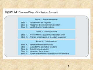
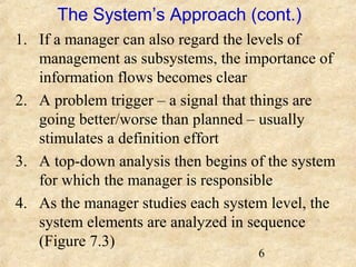
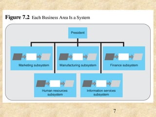
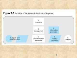
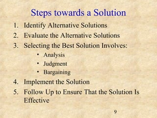
- The systems approach involves viewing an organization as a system and analyzing its parts, identifying alternative solutions, and selecting the best one.
- The systems development life cycle (SDLC) applies this approach to developing information systems and includes phases like planning, analysis, design, and implementation.
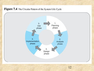
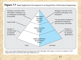
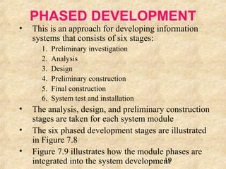
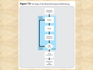
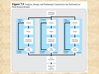
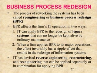
- Common SDLC methodologies are the traditional waterfall model, prototyping, rapid application development, phased development, and business process redesign.
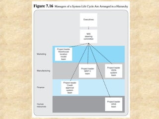
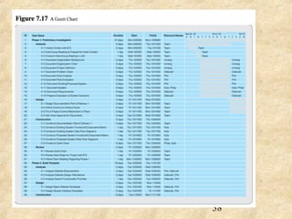
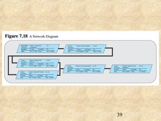
- Project management oversees development projects through hierarchical structures like steering committees and uses tools like Gantt charts and network diagrams.