sibt.nsw.edu.au navitas.com
Calculation oftruss forces using joint method
Example: Analyse the internal forces in the members of the truss.
E D
C
A
2 kN
ƩMc = 0
+ Ay (6) - 2 (3) = 0
Ay = 1 kN
The assumed direction of Ay is right!!
Ay
Cx
Cy
ƩFy = 0
Ay + Cy = 0
1 + Cy = 0
Cy = -1 kN
The assumed direction of Cy is wrong!
ƩFx = 0
-2 - Cx = 0
Cx = - 2 kN
The assumed direction of Cx is wrong!
First draw FBD for the complete system.
Second Apply ƩM = 0 at the point of highest number unknown forces to find the forces at system boundary.
4.
Ay = 1kN
Cy = 1 kN
Cx = 2 kN
ƩFy = 0
Fcd - 1 = 0
Fcd = 1 kN
The assumed direction of Fcd is right!
ƩFx = 0
- Fcb + 2 = 0
Fcb = 2 kN
The assumed direction of Fcb is right!
Fcd
2 kN
Consider joint C Draw FBD for this joint
Fcb
1 kN
Start at a boundary joint with minimum number of unknown forces.
Apply ƩFy = 0, ƩFx = 0 at that point
5.
Move to internaljoints
Ay = 1 kN
Cy = 1 kN
Cx = 2 kN
ƩFy = 0
- Fdb cos 45 - 1 = 0
Fdb = - 1.41 kN
The assumed direction of Fdb is wrong.
Fdb = 1.41 kN (C )
ƩFx = 0
- Fed - 2 – Fdb cos 45 = 0
- Fed - 2 - (-1.41 cos 45) = 0
Fed = -1 kN
The assumed direction of Fed is wrong!
Fed = 1 kN (C )
Fed
2 kN
45o
Consider joint D draw FBD for this joint
Fdb 1 kN
Consider joint E Draw FBD for this joint
1 kN
45o
Fea
Feb
ƩFx = 0
- Fea cos 45 - 1 = 0
Fea = -1.414 kN
The assumed direction of Fea is wrong.
Fea = 1.414 kN (C)
ƩFy = 0
- Fea cos 45 – Feb = 0
- (-1.414) cos 45 - Feb = 0
Feb = 1 kN
The assumed direction of Feb is right!
Feb = 1 kN (T )
6.
Ay = 1kN
Cy = 1 kN
Cx = 2 kN
ƩFx = 0
Fab - 1.414cos 45 = 0
Fab = 1 kN
The assumed direction of Fab is right!
Fab = 1 kN (T )
Summary:
Fcd = 1 kN (T), Fcb = 2kN (T),
Fdb = 1.41 kN (C), Fed = 1 kN (C ),
Fea = 1.41 kN (C), Feb = 1 kN (T ),
Fab = 1 kN (T ).
Fab
45o
Consider joint A Draw FBD for this joint
1 kN
1.414 kN
7.
Example: Method ofjoints – Bridge model
Analyse the internal forces in the members of the truss. All members have the same length.
If all members has the same length then we have equal angles (60°
) triangles .
8 kN
4 kN 2 kN
Ax
Ay
Cx
60°
8.
8 kN
4 kN2 kN
Ax
Ay
Cx
Let the length of the member be x
ƩMa = 0
8x + 4(x/2) + 2(3x/2) - Cx cos 60 (2x) = 0
8x + 2x +3x – Cx (x) = 0
13x = Cx (x)
Cx = 13 kN
ƩFy = 0
-Ay – 4 – 2 – 8 + Cx cos 60 = 0
-Ay – 14 + 13 cos 60 = 0
Ay = - 7.5 kN
ƩFx = 0
Ax - Cx cos 30 = 0
Ax - 13 cos 30 = 0
Ax = 11.26 kN
Consider joint A
7.5 kN
Fab
11.26 kN
Fae
60o
ƩFy = 0
7.5 – Fae cos30 = 0
Fae = 8.66kN
The assumed direction of Fae is right!
Fae = 8.66 kN (T )
ƩFx = 0
Fab + 11.26 + Fae cos 60 = 0
Fab + 11.26 +8.66 cos 60 = 0
Fab = -15.59 kN
The assumed direction of Fab is wrong!
Fab = 15.59 (C)
9.
ƩFy = 0
8.66cos 30 + Feb cos30 - 4 = 0
7.5 + Feb (0.866) - 4 = 0
Feb = - 4.04 kN
The assumed direction of Feb is wrong!
Feb = 4.04 kN (C )
Feb
Fed
Consider joint E
8.66 kN
4kN
60o
60o
ƩFx = 0
-8.66 cos 60 - Feb cos60 + Fed = 0
- 4.33 - 4.04 (0.5) + Fed = 0
Fed = 6.35 kN
The assumed direction of Fed is right!
Fed = 6.35 kN (T )
15.59 kN
Consider joint B 4.04 kN Fbd
60o
60o
60o
8kN
ƩFy = 0
4.04 cos30 - Fbd cos30 - 8 = 0
Fbd cos30 = - 4.5 kN
Fbd = - 5.2 kN
The assumed direction of Fbd is wrong!
Fbd = 5.2 kN (C )
ƩFx = 0
15.59 + 4.04 cos60 - Fbd cos 60 + Fbc = 0
15.59 + 2.02 – 5.2 (0.5) + Fbc = 0
Fbc = -15.01 kN
The assumed direction of Fbc is wrong!
Fbc = 15.01 kN (C )
Example: Method ofjoints
Analyse the internal forces in the members of the truss.
3 kN
Ax
Ay
Ex
Consider joint C
Fbc
3kN
30o
ƩFx = 0
-Fde cos 30 – 6 cos 30 = 0
Fde = - 6 kN
The assumed direction of Fde is wrong!
Fde = 6 kN (C )
ƩFy = 0
- Fde cos 60 – Fcd cos 60 + Fbd = 0
- 6 cos 60 – 6 cos 60 + Fbd = 0
Fbd = 6 kN
The assumed direction of Fbd is right!
Fbd = 6 kN (T )
Fbd
Fde Fcd = 6 kN (C )
60o
ƩFx = 0
-Fde cos 30 – 6 cos 30 = 0
Fde = - 6 kN
The assumed direction of Fde is wrong!
Fde = 6 kN (C )
Consider joint D
ƩFy = 0
- Fde cos 60 – Fcd cos 60 + Fbd = 0
- 6 cos 60 – 6 cos 60 + Fbd = 0
Fbd = 6 kN
The assumed direction of Fbd is right!
Fbd = 6 kN (T )
12.
ƩFy = 0
Fbacos 60 – Fbd = 0
Fba (0.5) – 6 = 0
Fba = 12kN
The assumed direction of Fba is right!
Fba = 12 kN (T )
Fbe
Fbd = 6 kN (T)
Consider joint B
ƩFx = 0
- Fba cos 30 – Fbe + Fbc = 0
- 12 cos 30 – Fbe + 5.2 = 0
Fbe = - 5.19 kN
The assumed direction of Fbe is wrong!
Fbe = 5.19 kN (C )
Fbc = 5.2 kN (T )
30o
Fba
Consider joint E
ƩFy = 0
Fae + Fed cos 60 = 0
Fae + 6 (0.5) = 0
Fae = - 3kN
The assumed direction of Fae is wrong!
Fae = 3 kN (C )
Summary: Fcd = 6 kN (C ), Fbc = 5.2 kN
(T), Fde = 6 kN (C), Fbd = 6 kN (T ),
Fba = 12 kN (T), Fbe = 5.19 kN (C ),
Fae = 3 kN (C ).
Fae
Feb = 5.2 kN (C )
30o
Fed = 6 kN (C )
Ex
13.
Trusses
Zero force members
Isit possible to have a zero-force member in a truss?
How to identify zero-force members?
2 conditions
1. If two members form a truss joint and NO external load or
support reaction is applied to the joint, the two members must
be zero force members.
2. If three members form a truss joint for which two of the members
are collinear, the third member is a zero-force member provided
NO external force or support reaction is applied to the joint.
Why do we need to design zero-force members?
1. To increase stability of truss during construction and to provide
added support if the loading is changed.
2. Truss analysis using the method of joints is greatly simplified if
we can first identify those members which support no loading.
14.
Trusses
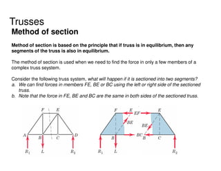
Method of section
Methodof section is based on the principle that if truss is in equilibrium, then any
segments of the truss is also in equilibrium.
The method of section is used when we need to find the force in only a few members of a
complex truss seystem.
Consider the following truss system, what will happen if it is sectioned into two segments?
a. We can find forces in members FE, BE or BC using the left or right side of the sectioned
truss.
b. Note that the force in FE, BE and BC are the same in both sides of the sectioned truss.
15.
Method of section
Atruss can be sectioned in many different ways.
SECTION 1 SECTION 2
16.
Example :Determine theforce in member BE of the loaded truss by the
two methods, method of joints and method of section
Ax
Ay
Gy
4 kN
5 kN
6 kN
ƩMa = 0
4 (2) + 5( 4) + 6( 6 ) - Gy (3 ) = 0
64 – Gy (3) = 0
Gy = 21.33 kN
ƩFy = 0
Ay + 21.33 = 0
Ay = -21.33 kN
ƩFx = 0
Ax – 4 – 5 - 6 = 0
Ax - 15 = 0
Ax = 15 kN
17.
15 kN
21.33 kN
Gy= 21.33 kN
4 kN
Fbc
Fbe Fef
Fbe Fef
Fbc
5 kN
6 kN
Bottom section of truss
Top section of truss
18.
Determine the forcein member BE of the loaded truss.
Fbe Fef
Fbc
5 kN
6 kN
ƩMd = 0
- 5(2) + Fbe cos 63.44 (2) + Fbe sin 63.44 (1 ) = 0
- 10 + Fbe (0.894) + Fbe (0.894) = 0
Fbe = 5.59 kN
The assumed direction of Fbe is right!
Fbe = 5.59 kN (T )
1m
63.44o
19.
Calculate the forcein members AB, BG and GF.
O
6 kN
Y = 12-2.4 = 9.6m
5/x = 2/(x-7.2)
5 (x – 7.2) = 2x
5x – 2x = 36
x = 12m
x
O
Fab
Fbg
Fgf
Can you think of the easiest way to solve the problem?
20.
Calculate the forcein members AB, BG and GF.
6 kN
Y = 12-2.4 = 9.6m
O
ƩMo = 0
- Fbg (9.6) – 6 (12- 2.4 – 2.4 – 2.4) = 0
-9.6 Fbg – 28.8 = 0
Fbg = - 3 kN
The assumed direction of Fbe is wrong!
Fbg = 3 kN (C )
Fab
Fbg
Fgf
ƩMf = 0
What is the length of Cf?
-Fab (3) + Fbg (2.4) + 6 (2.4) = 0
- 3 Fab + 3(2.4) + 14.4 = 0
Fab = 7.2 kN (T)
21.
Calculate the forcein members AB, BG and GF.
6 kN
Y = 12-2.4 = 9.6m
O
Fab
Fbg
Fgf
67.38o
ƩFx = 0
- Fab – Fgf cos 22.62 = 0
- 7.2 – Fgf cos 22.62 = 0
Fgf = - 7.8 kN
Fgf = 7.8 kN (C)
22.
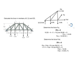
Calculate the forcein members JK, CJ and CD.
Fkj
10.33 kN
Determine the reaction force Ay,
Ay = 10.33 kN
Fcd
Fcj
4 kN 5 kN
ƩMc = 0
10.33 (4) + Fkj (3) – 4 (2) = 0
3 Fkj = -33.33 kN
Fkj = - 11.11 kN
Fkj = 11.11 kN ( C)
23.
Calculate the forcein members JK, CJ and CD.
Fkj
10.33 kN
Determine the force Fcj,
Fcd
Fcj
4 kN 5 kN
ƩFx = 0
Fkj + Fcd + Fci cos (56.31) = 0
-11.11 + Fcd -1.6 cos 56.31 = 0
Fcd = 12 kN
Fcd = 12 kN ( T)
ƩFy = 0
10.33 – 4 – 5 + Fcj cos 33.69 = 0
Fcj = -1.6 kN
Fcj = 1.6 kN (C )
Determine the force Fcd,