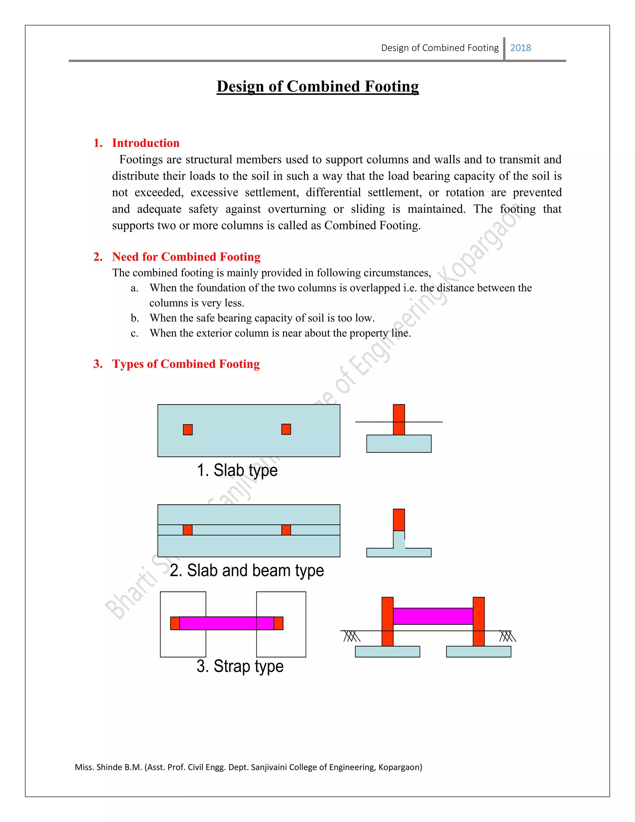
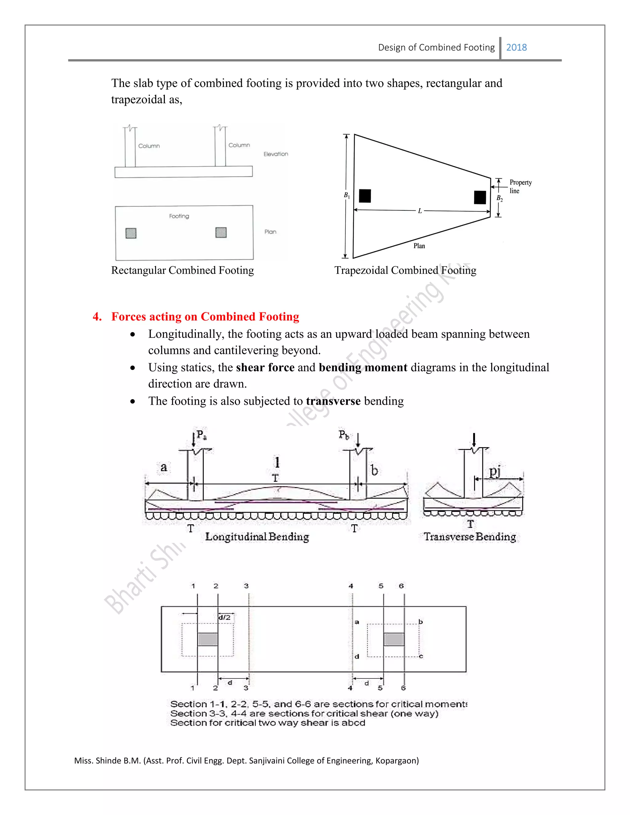
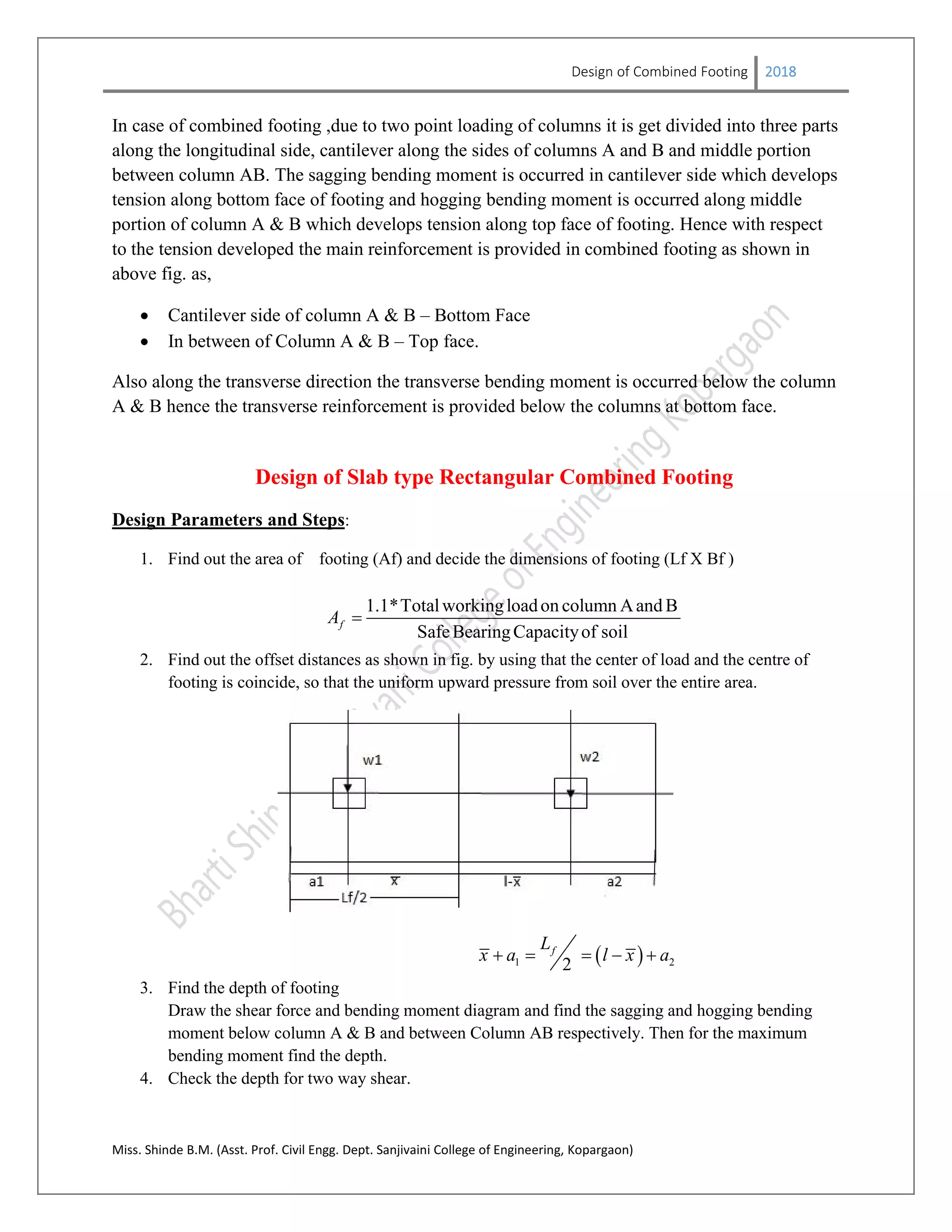
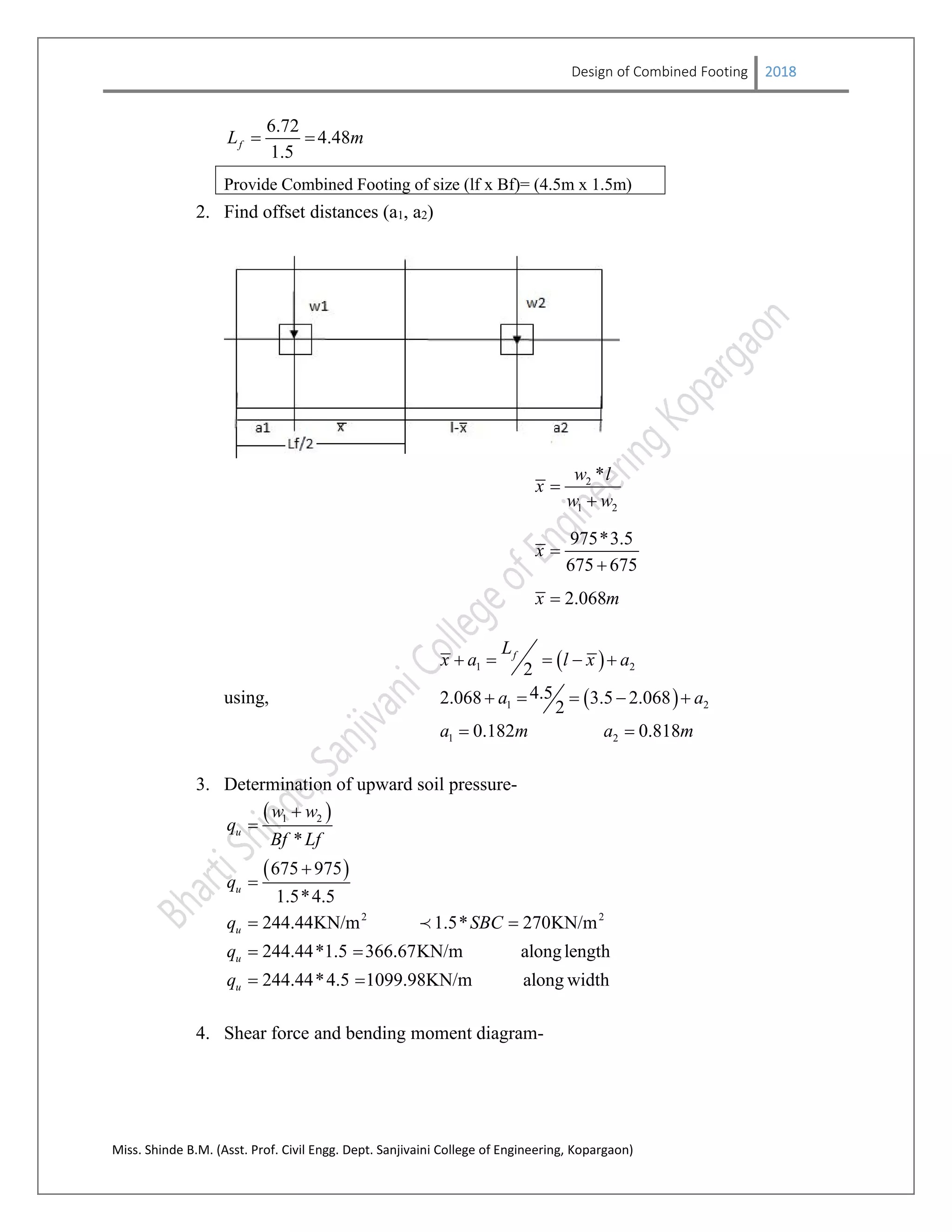
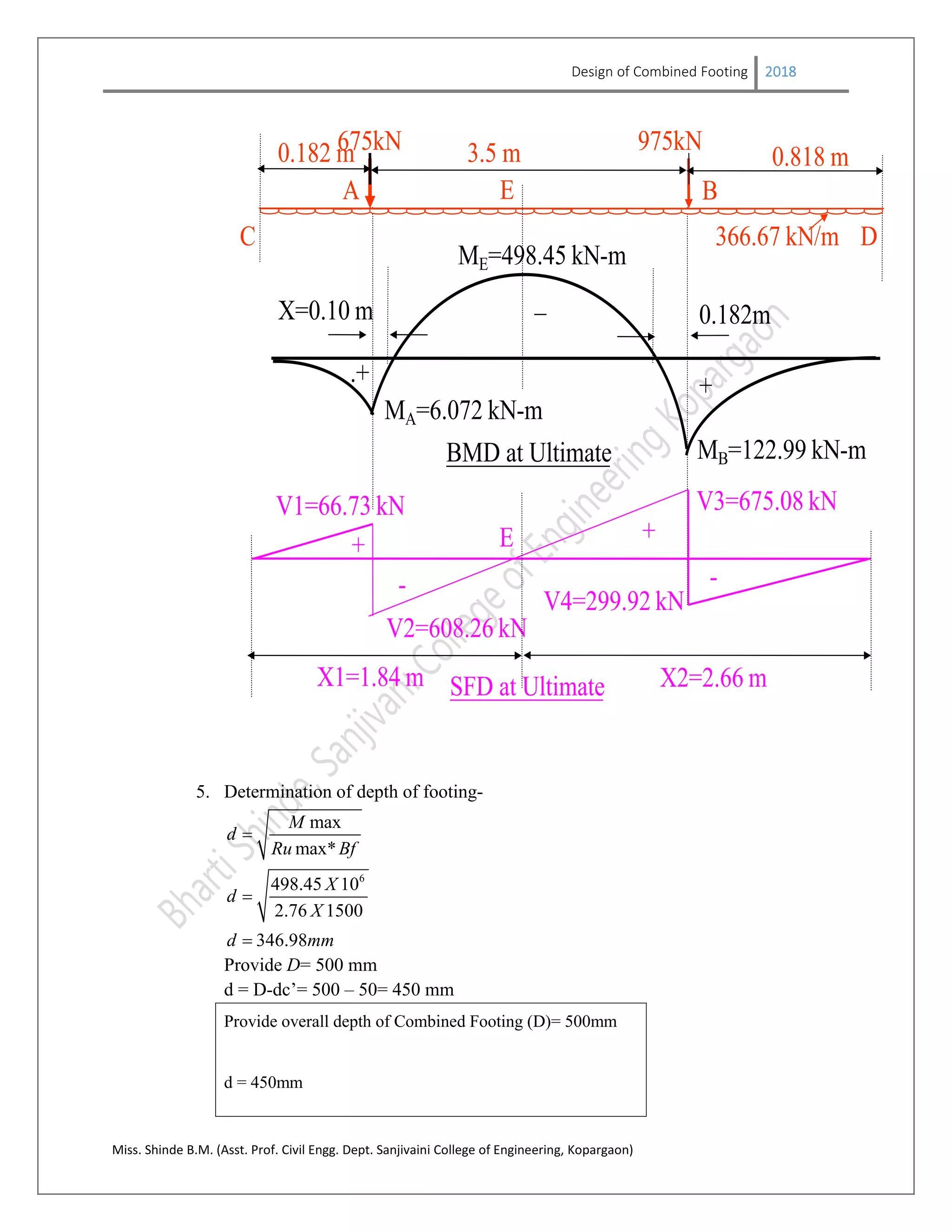
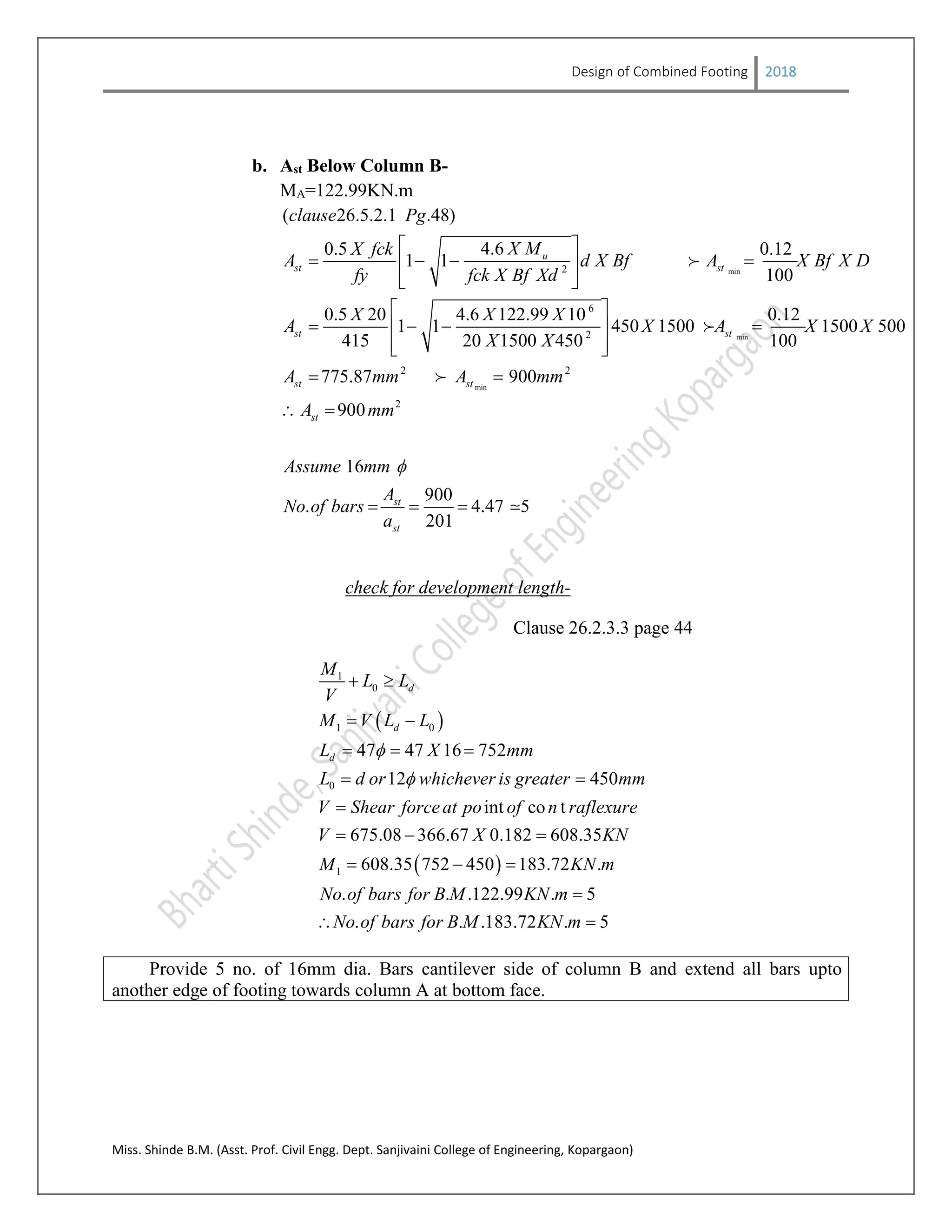
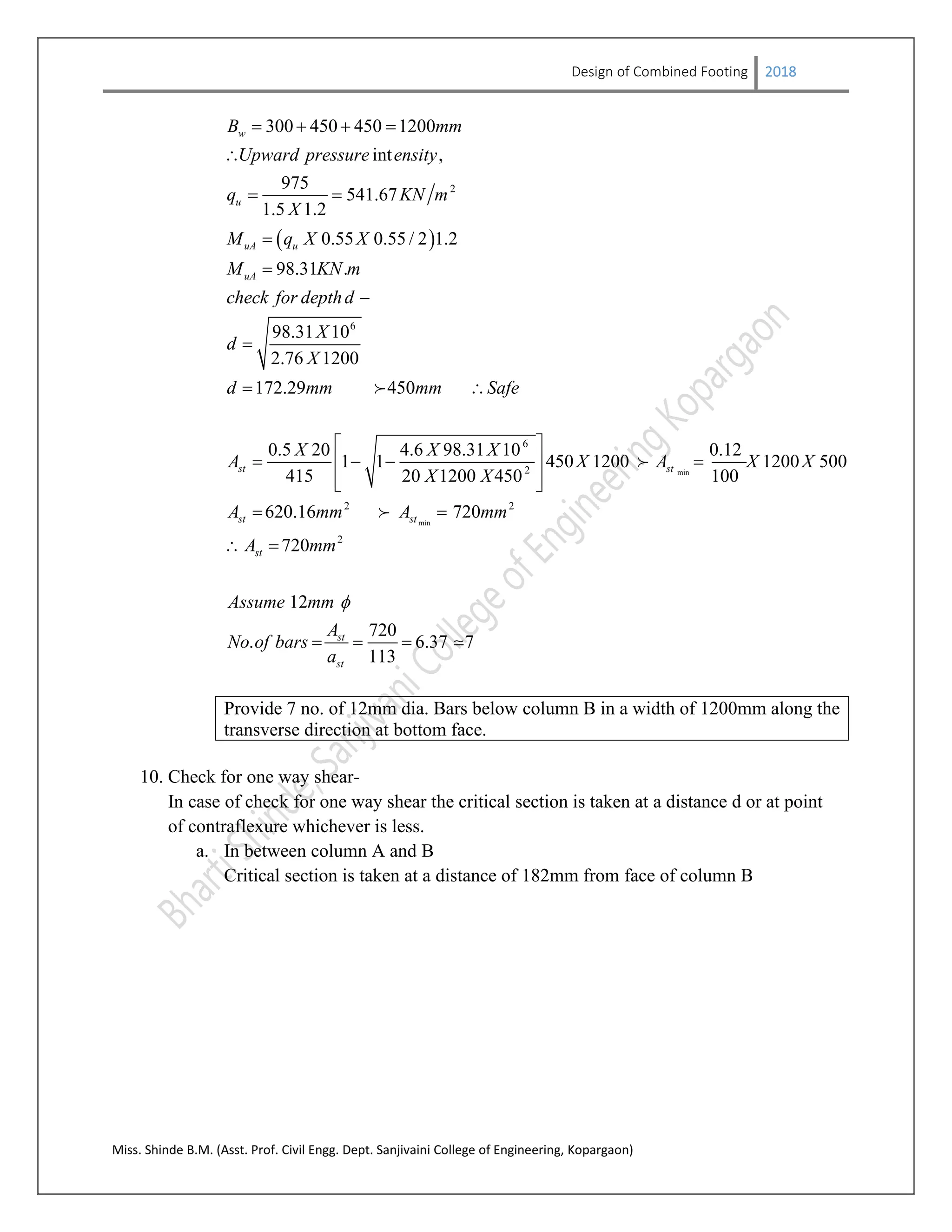
The document discusses the design of a combined footing to support two columns. It first defines what a combined footing is and why it is used. It then describes the types of combined footings and the forces acting on it. The document provides the design steps for a rectangular combined footing, which include determining dimensions, reinforcement requirements, and design checks. As an example, it shows the detailed design of a rectangular combined footing supporting two columns with loads of 450kN and 650kN respectively. The design includes calculating dimensions, reinforcement, development lengths, and design checks.
information on types of beams, different methods to calculate beam stress, design for shear, analysis for SRB flexure, design for flexure, Design procedure for doubly reinforced beam,
Design and Detailing of RC Deep beams as per IS 456-2000VVIETCIVIL
Visit : https://teacherinneed.wordpress.com/
1. DEEP BEAM DEFINITION - IS 456
2. DEEP BEAM APPLICATION
3. DEEP BEAM TYPES
4. BEHAVIOUR OF DEEP BEAMS
5. LEVER ARM
6. COMPRESSIVE FORCE PATH CONCEPT
7. ARCH AND TIE ACTION
8. DEEP BEAM BEHAVIOUR AT ULTIMATE LIMIT STATE
9. REBAR DETAILING
10. EXAMPLE 1 – SIMPLY SUPPORTED DEEP BEAM
11. EXAMPLE 2 – SIMPLY SUPPORTED DEEP BEAM; M20, FE415
12. EXAMPLE 3: FIXED ENDS AND CONTINUOUS DEEP BEAM
13. EXAMPLE 4 : FIXED ENDS AND CONTINUOUS DEEP BEAM
This document will help you learn an introductory part and some detailed information on Shallow Foundations. As I am presenting this document to you I wish you all a Happy learning arena. It is highly recommended for students taking a bachelor degree in Civil Engineering, also it is a good document for students who are doing final touches for their examinations.
Gantry girder
Gantry girder or crane girder hand operated or electrically operated overhead cranes in industrial building such as factories, workshops, steel works, etc. to lift heavy materials, equipment etc. and carry them from one location to other , within the building
The GANTRY GIRDER spans between brackets attached to columns, which may either be of steel or reinforced concrete. Thus the span of gantry girder is equal to centre to centre spacing of columns. The rails are mounted on gantry girders.
Loads acting on gantry girder
Gantry girder, having no lateral support in its length (laterally unsupported) has to withstand the following loads:
1. Vertical loads from crane :
Self weight of crane girder
Hook load
Weight of crab (trolley)
2. Impact load from crane :
As the load is lifted using the crane hook and moved from one place to another, and released at the required place, an impact is felt on the gantry girder.
3. Longitudinal horizontal force (Drag force) :
This is caused due to the starting and stopping of the crane girder moving over the crane rails, as the crane girder moves longitudinally, i.e. in the direction of gantry girder.
This force is also known as braking force, or drag force.
This force is taken equal to 5% of the static wheel loads for EOT or hand operated cranes.
4. Lateral load (Surge load) :
Lateral forces are caused due to sudden starting or stopping of the crab when moving over the crane girder.
Lateral forces are also caused when the crane is dragging weights across the' floor of the shop.
Types of gantry girders
Depending upon the span and crane capacity, there can be many forms of gantry girders. Some commonly used forms are shows in fig .
Rolled steel beams with or without plates, channels or angles are normally used for spans up to 8m and for cranes up to 50kN capacity.
Plate girder are suitable up to span 6 to 10 m.
Plate girder with channels, angles, etc. can be used for spans more than 10m
Box girder are used foe spans more than 12m.
Name: Sadia Mahajabin
ID : 10.01.03.098
4th year 2nd Semester
Section : B
Department of Civil Engineering
Ahsanullah University of Science and Technology
Basic concepts, resolution of force, parallel and non-concurrent force system, moment of force, couple, Varignon’s theorem, resultant of concurrent and non-concurrent forces
All the fundamentals of mechanics of Solids are explained, Topics covered are Simple stress and Strain, Shear force and bending moment diagram, Bending and shear stress, Torsion, Axially loaded column, Principle stresses and strains.
About
Indigenized remote control interface card suitable for MAFI system CCR equipment. Compatible for IDM8000 CCR. Backplane mounted serial and TCP/Ethernet communication module for CCR remote access. IDM 8000 CCR remote control on serial and TCP protocol.
• Remote control: Parallel or serial interface.
• Compatible with MAFI CCR system.
• Compatible with IDM8000 CCR.
• Compatible with Backplane mount serial communication.
• Compatible with commercial and Defence aviation CCR system.
• Remote control system for accessing CCR and allied system over serial or TCP.
• Indigenized local Support/presence in India.
• Easy in configuration using DIP switches.
Technical Specifications
Indigenized remote control interface card suitable for MAFI system CCR equipment. Compatible for IDM8000 CCR. Backplane mounted serial and TCP/Ethernet communication module for CCR remote access. IDM 8000 CCR remote control on serial and TCP protocol.
Key Features
Indigenized remote control interface card suitable for MAFI system CCR equipment. Compatible for IDM8000 CCR. Backplane mounted serial and TCP/Ethernet communication module for CCR remote access. IDM 8000 CCR remote control on serial and TCP protocol.
• Remote control: Parallel or serial interface
• Compatible with MAFI CCR system
• Copatiable with IDM8000 CCR
• Compatible with Backplane mount serial communication.
• Compatible with commercial and Defence aviation CCR system.
• Remote control system for accessing CCR and allied system over serial or TCP.
• Indigenized local Support/presence in India.
Application
• Remote control: Parallel or serial interface.
• Compatible with MAFI CCR system.
• Compatible with IDM8000 CCR.
• Compatible with Backplane mount serial communication.
• Compatible with commercial and Defence aviation CCR system.
• Remote control system for accessing CCR and allied system over serial or TCP.
• Indigenized local Support/presence in India.
• Easy in configuration using DIP switches.
Sachpazis:Terzaghi Bearing Capacity Estimation in simple terms with Calculati...Dr.Costas Sachpazis
Terzaghi's soil bearing capacity theory, developed by Karl Terzaghi, is a fundamental principle in geotechnical engineering used to determine the bearing capacity of shallow foundations. This theory provides a method to calculate the ultimate bearing capacity of soil, which is the maximum load per unit area that the soil can support without undergoing shear failure. The Calculation HTML Code included.
Final project report on grocery store management system..pdfKamal Acharya
In today’s fast-changing business environment, it’s extremely important to be able to respond to client needs in the most effective and timely manner. If your customers wish to see your business online and have instant access to your products or services.
Online Grocery Store is an e-commerce website, which retails various grocery products. This project allows viewing various products available enables registered users to purchase desired products instantly using Paytm, UPI payment processor (Instant Pay) and also can place order by using Cash on Delivery (Pay Later) option. This project provides an easy access to Administrators and Managers to view orders placed using Pay Later and Instant Pay options.
In order to develop an e-commerce website, a number of Technologies must be studied and understood. These include multi-tiered architecture, server and client-side scripting techniques, implementation technologies, programming language (such as PHP, HTML, CSS, JavaScript) and MySQL relational databases. This is a project with the objective to develop a basic website where a consumer is provided with a shopping cart website and also to know about the technologies used to develop such a website.
This document will discuss each of the underlying technologies to create and implement an e- commerce website.
Explore the innovative world of trenchless pipe repair with our comprehensive guide, "The Benefits and Techniques of Trenchless Pipe Repair." This document delves into the modern methods of repairing underground pipes without the need for extensive excavation, highlighting the numerous advantages and the latest techniques used in the industry.
Learn about the cost savings, reduced environmental impact, and minimal disruption associated with trenchless technology. Discover detailed explanations of popular techniques such as pipe bursting, cured-in-place pipe (CIPP) lining, and directional drilling. Understand how these methods can be applied to various types of infrastructure, from residential plumbing to large-scale municipal systems.
Ideal for homeowners, contractors, engineers, and anyone interested in modern plumbing solutions, this guide provides valuable insights into why trenchless pipe repair is becoming the preferred choice for pipe rehabilitation. Stay informed about the latest advancements and best practices in the field.
Hierarchical Digital Twin of a Naval Power SystemKerry Sado
A hierarchical digital twin of a Naval DC power system has been developed and experimentally verified. Similar to other state-of-the-art digital twins, this technology creates a digital replica of the physical system executed in real-time or faster, which can modify hardware controls. However, its advantage stems from distributing computational efforts by utilizing a hierarchical structure composed of lower-level digital twin blocks and a higher-level system digital twin. Each digital twin block is associated with a physical subsystem of the hardware and communicates with a singular system digital twin, which creates a system-level response. By extracting information from each level of the hierarchy, power system controls of the hardware were reconfigured autonomously. This hierarchical digital twin development offers several advantages over other digital twins, particularly in the field of naval power systems. The hierarchical structure allows for greater computational efficiency and scalability while the ability to autonomously reconfigure hardware controls offers increased flexibility and responsiveness. The hierarchical decomposition and models utilized were well aligned with the physical twin, as indicated by the maximum deviations between the developed digital twin hierarchy and the hardware.
Immunizing Image Classifiers Against Localized Adversary Attacksgerogepatton
This paper addresses the vulnerability of deep learning models, particularly convolutional neural networks
(CNN)s, to adversarial attacks and presents a proactive training technique designed to counter them. We
introduce a novel volumization algorithm, which transforms 2D images into 3D volumetric representations.
When combined with 3D convolution and deep curriculum learning optimization (CLO), itsignificantly improves
the immunity of models against localized universal attacks by up to 40%. We evaluate our proposed approach
using contemporary CNN architectures and the modified Canadian Institute for Advanced Research (CIFAR-10
and CIFAR-100) and ImageNet Large Scale Visual Recognition Challenge (ILSVRC12) datasets, showcasing
accuracy improvements over previous techniques. The results indicate that the combination of the volumetric
input and curriculum learning holds significant promise for mitigating adversarial attacks without necessitating
adversary training.
Overview of the fundamental roles in Hydropower generation and the components involved in wider Electrical Engineering.
This paper presents the design and construction of hydroelectric dams from the hydrologist’s survey of the valley before construction, all aspects and involved disciplines, fluid dynamics, structural engineering, generation and mains frequency regulation to the very transmission of power through the network in the United Kingdom.
Author: Robbie Edward Sayers
Collaborators and co editors: Charlie Sims and Connor Healey.
(C) 2024 Robbie E. Sayers
Water scarcity is the lack of fresh water resources to meet the standard water demand. There are two type of water scarcity. One is physical. The other is economic water scarcity.
1. Design of Combined Footing 2018
Miss. Shinde B.M. (Asst. Prof. Civil Engg. Dept. Sanjivaini College of Engineering, Kopargaon)
Design of Combined Footing
1. Introduction
Footings are structural members used to support columns and walls and to transmit and
distribute their loads to the soil in such a way that the load bearing capacity of the soil is
not exceeded, excessive settlement, differential settlement, or rotation are prevented
and adequate safety against overturning or sliding is maintained. The footing that
supports two or more columns is called as Combined Footing.
2. Need for Combined Footing
The combined footing is mainly provided in following circumstances,
a. When the foundation of the two columns is overlapped i.e. the distance between the
columns is very less.
b. When the safe bearing capacity of soil is too low.
c. When the exterior column is near about the property line.
3. Types of Combined Footing
2. Slab and beam type
3. Strap type
1. Slab type
2. Design of Combined Footing 2018
Miss. Shinde B.M. (Asst. Prof. Civil Engg. Dept. Sanjivaini College of Engineering, Kopargaon)
The slab type of combined footing is provided into two shapes, rectangular and
trapezoidal as,
Rectangular Combined Footing Trapezoidal Combined Footing
4. Forces acting on Combined Footing
Longitudinally, the footing acts as an upward loaded beam spanning between
columns and cantilevering beyond.
Using statics, the shear force and bending moment diagrams in the longitudinal
direction are drawn.
The footing is also subjected to transverse bending
3. Design of Combined Footing 2018
Miss. Shinde B.M. (Asst. Prof. Civil Engg. Dept. Sanjivaini College of Engineering, Kopargaon)
In case of combined footing ,due to two point loading of columns it is get divided into three parts
along the longitudinal side, cantilever along the sides of columns A and B and middle portion
between column AB. The sagging bending moment is occurred in cantilever side which develops
tension along bottom face of footing and hogging bending moment is occurred along middle
portion of column A & B which develops tension along top face of footing. Hence with respect
to the tension developed the main reinforcement is provided in combined footing as shown in
above fig. as,
Cantilever side of column A & B – Bottom Face
In between of Column A & B – Top face.
Also along the transverse direction the transverse bending moment is occurred below the column
A & B hence the transverse reinforcement is provided below the columns at bottom face.
Design of Slab type Rectangular Combined Footing
Design Parameters and Steps:
1. Find out the area of footing (Af) and decide the dimensions of footing (Lf X Bf )
1.1*Totalworkingloadon column Aand B
SafeBearingCapacityof soil
fA
2. Find out the offset distances as shown in fig. by using that the center of load and the centre of
footing is coincide, so that the uniform upward pressure from soil over the entire area.
1 22
fL
x a l x a
3. Find the depth of footing
Draw the shear force and bending moment diagram and find the sagging and hogging bending
moment below column A & B and between Column AB respectively. Then for the maximum
bending moment find the depth.
4. Check the depth for two way shear.
4. Design of Combined Footing 2018
Miss. Shinde B.M. (Asst. Prof. Civil Engg. Dept. Sanjivaini College of Engineering, Kopargaon)
5. Find the area of reinforcement for sagging and hogging bending moment in longitudinal direction
and provide along tension face. Further apply the development length check as per IS 456-2000,
and curtail the reinforcement.
1
0 d
M
L L
V
6. Find the transverse reinforcement below the column A & B. The transverse action of the footing
is occurring on width of (b+2d) called bandwidth, where b-is the width of column and d- is the
depth of footing.
7. Check for one way shear and if it is unsafe provide the shear reinforcement as per IS 456-2000.
8. Draw the sections along the longitudinal and transverse direction and show the reinforcement
details.
Example 1
Design a reinforced concrete combined rectangular footing for two columns A & B
carrying working loads 450KN & 650KN respectively. Column A is 300mm x 300mm
and column B is 300mm x 400mm size. The center to center distance of column is 3.5m.
Safe bearing capacity of soil is 180KN/m2
Use M20 and Fe415 materials. Draw all
details of reinforcement.
Ans:
Given-
Data Column A Column B
Size 300mm x 300mm 300mm x 400mm
Working load 450KN 650KN
Ultimate load (w)
(F.S=1.5)
675KN 975KN
C/C distance (l) 3.5m
SBC 180KN/m2
Materials M20 and Fe415
Design constants Kumax=0.48, Rumax=2.76,
Ptmax=0.96%
1. Determination of dimensions of footing (Lf x Bf)-
2
1.1*Totalworkingloadon column Aand B
SafeBearingCapacityof soil
1.1* 450 650
180
6.72
f
f
f
A
A
A m
Assume Bf= 1.5m,
5. Design of Combined Footing 2018
Miss. Shinde B.M. (Asst. Prof. Civil Engg. Dept. Sanjivaini College of Engineering, Kopargaon)
6.72
4.48
1.5
fL m
Provide Combined Footing of size (lf x Bf)= (4.5m x 1.5m)
2. Find offset distances (a1, a2)
2
1 2
*
975*3.5
675 675
2.068
w l
x
w w
x
x m
using,
1 2
1 2
1 2
2
4.52.068 3.5 2.068
2
0.182 0.818
fL
x a l x a
a a
a m a m
3. Determination of upward soil pressure-
1 2
2 2
*
675 975
1.5*4.5
244.44KN/m 1.5* 270KN/m
244.44*1.5 366.67KN/m alonglength
244.44*4.5 1099.98KN/m along width
u
u
u
u
u
w w
q
Bf Lf
q
q SBC
q
q
4. Shear force and bending moment diagram-
6. Design of Combined Footing 2018
Miss. Shinde B.M. (Asst. Prof. Civil Engg. Dept. Sanjivaini College of Engineering, Kopargaon)
675kN 975kN
366.67 kN/m
0.182 m 0.818 m3.5 m
C
A B
D
E
ME=498.45 kN-m
MA=6.072 kN-m
+
_
.+
X=0.10 m 0.182m
MB=122.99 kN-mBMD at Ultimate
V1=66.73 kN
V4=299.92 kN
V2=608.26 kN
V3=675.08 kN
SFD at Ultimate
+
+
-
X1=1.84 m X2=2.66 m
E
-
5. Determination of depth of footing-
6
max
max*
498.45 10
2.76 1500
346.98
M
d
Ru Bf
X
d
X
d mm
Provide D= 500 mm
d = D-dc’= 500 – 50= 450 mm
Provide overall depth of Combined Footing (D)= 500mm
d = 450mm
7. Design of Combined Footing 2018
Miss. Shinde B.M. (Asst. Prof. Civil Engg. Dept. Sanjivaini College of Engineering, Kopargaon)
6. Check depth for two way shear-
For column B load is more, hence consider check for column B
Critical section for two way shear is taken at a distance of d/2 from face of
column B.
0
0
0 0
3
300 750
2 2
400 850
2 2
,
675 975
975 0.75 0.85
1.5 4.5
819.17
2 3200
,
819.17 10
3200 450
0.568
u
u
u
u
u
d d
L mm
d d
B mm
Punching Shear Force
V X
X
V KN
Perimeter L B mm
Punching Shear Stress
V X
PerimeterX d X
MPa
As per clause 31.6.3.1 page 58 & 59
0.5
0.3
0.5
0.4
1.25 1.0
1.0
0.25 0.25 20 1.118
* 1.118
c
c c
short sizeof column
Ks
long sizeof column
Ks
Ks
Ks
X fck X MPa
Ks PMPa
8. Design of Combined Footing 2018
Miss. Shinde B.M. (Asst. Prof. Civil Engg. Dept. Sanjivaini College of Engineering, Kopargaon)
, 0.568 1.118u ccomparing safe
7. Design of Longitudinal Reinforcement-
a. Ast Below Column A-
MA=6.072KN.m
min
min
min
2
6
2
2 2
( 26.5.2.1 .48)
4.60.5 0.12
1 1
100
0.5 20 4.6 6.072 10 0.12
1 1 450 1500 1500 500
415 20 1500 450 100
37.43 900
900
u
st st
st st
st st
st
clause Pg
X MX fck
A d X Bf A X Bf X D
fy fck X Bf Xd
X X X
A X A X X
X X
A mm A mm
A m
2
16
900
. 4.47 5
201
st
st
m
Assume mm
A
No of bars
a
check for development length-
Clause 26.2.3.3 page 44
1
0
1 0
0
1
47 47 16 752
12 450
int co t
608.26 366.67 0.1 571.59
571.59 752 450 172.62 .
. . .6.072 . 5
. .
d
d
d
M
L L
V
M V L L
L X mm
L d or whichever is greater mm
V Shear forceat po of n raflexure
V X KN
M KN m
No of bars for B M KN m
No of bars for B
.172.62 . 5M KN m
Provide 5 no. of 16mm dia. Bars cantilever side of column A and extend all bars upto
another edge of footing towards column B at bottom face.
9. Design of Combined Footing 2018
Miss. Shinde B.M. (Asst. Prof. Civil Engg. Dept. Sanjivaini College of Engineering, Kopargaon)
b. Ast Below Column B-
MA=122.99KN.m
min
min
min
2
6
2
2 2
( 26.5.2.1 .48)
4.60.5 0.12
1 1
100
0.5 20 4.6 122.99 10 0.12
1 1 450 1500 1500 500
415 20 1500 450 100
775.87 900
90
u
st st
st st
st st
st
clause Pg
X MX fck
A d X Bf A X Bf X D
fy fck X Bf Xd
X X X
A X A X X
X X
A mm A mm
A
2
0
16
900
. 4.47 5
201
st
st
mm
Assume mm
A
No of bars
a
check for development length-
Clause 26.2.3.3 page 44
1
0
1 0
0
1
47 47 16 752
12 450
int co t
675.08 366.67 0.182 608.35
608.35 752 450 183.72 .
. . .122.99 . 5
.
d
d
d
M
L L
V
M V L L
L X mm
L d or whichever is greater mm
V Shear forceat po of n raflexure
V X KN
M KN m
No of bars for B M KN m
No of bars fo
. .183.72 . 5r B M KN m
Provide 5 no. of 16mm dia. Bars cantilever side of column B and extend all bars upto
another edge of footing towards column A at bottom face.
10. Design of Combined Footing 2018
Miss. Shinde B.M. (Asst. Prof. Civil Engg. Dept. Sanjivaini College of Engineering, Kopargaon)
c. Ast Between Column A and Column B-
MA=498.45KN.m
min
min
min
2
6
2
2 2
( 26.5.2.1 .48)
4.60.5 0.12
1 1
100
0.5 20 4.6 498.45 10 0.12
1 1 450 1500 1500 500
415 20 1500 450 100
3435.29 900
3
u
st st
st st
st st
st
clause Pg
X MX fck
A d X Bf A X Bf X D
fy fck X Bf Xd
X X X
A X A X X
X X
A mm A mm
A
2
435.29
20
3435.29
. 10.9 11
314
st
st
mm
Assume mm
A
No of bars
a
check for development length-
Clause 26.2.3.3 page 44
1
0
1 0
0
1
47 47 16 752
12 450
int co t
608.26 366.67 0.1 571.59
571.59 752 450 172.62 .
. . .498.95 . 11
.
d
d
d
M
L L
V
M V L L
L X mm
L d or whichever is greater mm
V Shear forceat po of n raflexure
V X KN
M KN m
No of bars for B M KN m
No of bars for
172.62
. .172.62 . 11 3.8 4
498.95
B M KN m X
Provide11 no. of 20mm dia. Bars in between column A and B and extend 4 no. of bars upto
edge of footing on both sides of footing at top face.
9. Design of reinforcement along transverse direction-
The transverse reinforcement is provided below column A and column B for a length of
bandwidth.
11. Design of Combined Footing 2018
Miss. Shinde B.M. (Asst. Prof. Civil Engg. Dept. Sanjivaini College of Engineering, Kopargaon)
Bw = b+d+d or available distance whichever is less.
a. Below Column A
2
6
6
300 450 182 300 / 2 782 790
int ,
675
569.62
1.5 0.79
0.6 0.6 / 2 0.79
80.99 .
80.99 10
2.76 790
192.72 450
0.5 20 4.6 80.99 10
1 1
415
w
u
uA u
uA
st
B mm mm
Upward pressure ensity
q KN m
X
M q X X
M KN m
check for depthd
X
d
X
d mm mm Safe
X X X
A
min
min
2
2 2
2
0.12
450 790 790 500
20 790 450 100
514.16 426.6
514.41
12
514.41
. 4.55 5
113
st
st st
st
st
st
X A X X
X X
A mm A mm
A mm
Assume mm
A
No of bars
a
Provide 5 no. of 12mm dia. Bars below column A in a width of 790mm along the
transverse direction at bottom face.
b. Below Column A
12. Design of Combined Footing 2018
Miss. Shinde B.M. (Asst. Prof. Civil Engg. Dept. Sanjivaini College of Engineering, Kopargaon)
2
6
300 450 450 1200
int ,
975
541.67
1.5 1.2
0.55 0.55 / 2 1.2
98.31 .
98.31 10
2.76 1200
172.29 450
w
u
uA u
uA
B mm
Upward pressure ensity
q KN m
X
M q X X
M KN m
check for depthd
X
d
X
d mm mm Safe
min
min
6
2
2 2
2
0.5 20 4.6 98.31 10 0.12
1 1 450 1200 1200 500
415 20 1200 450 100
620.16 720
720
12
720
. 6.37 7
113
st st
st st
st
st
st
X X X
A X A X X
X X
A mm A mm
A mm
Assume mm
A
No of bars
a
Provide 7 no. of 12mm dia. Bars below column B in a width of 1200mm along the
transverse direction at bottom face.
10. Check for one way shear-
In case of check for one way shear the critical section is taken at a distance d or at point
of contraflexure whichever is less.
a. In between column A and B
Critical section is taken at a distance of 182mm from face of column B
13. Design of Combined Footing 2018
Miss. Shinde B.M. (Asst. Prof. Civil Engg. Dept. Sanjivaini College of Engineering, Kopargaon)
2
300
675.08 366.67 182
2
553.34
100 100 314
0.51%
1500 450
19, .73, 456 2000
0.483 /
0.483 1500 450
326.16 553.34
Pr inf
uD
uD
c
uc c
uc uD
V
V KN
Ast X
Pt
bd X
fromTable Pg IS
N mm
V bd X X
V KN V KN
ovide shear re orcement
A
3
10 ,2
40.4 .73
0.87* * *
0.75
227.18 0.75 450
0.87 415 157.1 450
337.5
227.18 10
112.52
v
uD uc
v
v
ssume mm legged vertical stirrups HYSD Steel
clause Pg
fy Asv d
S d
Vs
Vs V V KN X
X X X
S mm
X
S mm
Provide 2-legged 10mm dia. HYSD steel bar @ 110mm C/C in between col. A & B
b. In cantilever side of column A & B
Critical section is taken at a distance of 450mm from face of column B
2
300
300 366.67 450
2
80
100 100 201
0.148%
1500 450
19, .73, 456 2000
0.26 /
0.26 1500 450
182.25 80
Pr min inf
uD
uD
c
uc c
uc uD
V
V KN
Ast X
Pt
bd X
fromTable Pg IS
N mm
V bd X X
V KN V KN
ovide imum shear re orcement
Provide 2-legged 10mm dia. HYSD steel bar @ 250mm C/C in cantilever side
col. A & B
11. Summery-
14. Design of Combined Footing 2018
Miss. Shinde B.M. (Asst. Prof. Civil Engg. Dept. Sanjivaini College of Engineering, Kopargaon)
Description
Size of Footing 4.5M x 1.5M
Depth of footing D=500mm
d=450mm
Cantilever Col. A Between Col. A & B Cantilever Col. A
Long. R/F 5 no. of 16mm dia. 11 no. 20mm dia. 5 no. of 16mm dia.
Transverse R/F 5 no. of 12mm dia. ---- 7 no. of 12mm dia.
Shear R/F 2-legged 10mm dia.
HYSD steel bar @
250mm C/C
2-legged 10mm dia.
HYSD steel bar @
110mm C/C
2-legged 10mm dia.
HYSD steel bar @
250mm C/C
12. Reinforcement Details-
Design of Slab and Beam type Rectangular Combined Footing
Design Parameters and Steps:
1. Find out the area of footing (Af) and decide the dimensions of footing (Lf X Bf )
1.1*Totalworkingloadon column Aand B
SafeBearingCapacityof soil
fA
2. Find out the offset distances as shown in fig. by using that the center of load and the centre of
footing is coincide, so that the uniform upward pressure from soil over the entire area.
15. Design of Combined Footing 2018
Miss. Shinde B.M. (Asst. Prof. Civil Engg. Dept. Sanjivaini College of Engineering, Kopargaon)
1 22
fL
x a l x a
3. Design of Base Slab
Find net upward pressure,
21 2
/
*1.0 /
u
u u
w w
q KN m
Af
q q m KN m
2
2
offset distanceof col.Aor col.whicheverismore
Find Depth of Slab, d=
Check for one wayshear
Find Area of Main reinforcement and area of distribution steel
u
u
u
u
q l
M
l
M
R b
4. Design of Central Beam
Find net upward pressure,
21 2
/
* /
* /
u
u u
u u
w w
q KN m
Af
q q Bf KN m along length
q q Lf KN m along width
Draw the shear force and bending moment diagram and find the sagging and hogging bending
moment below column A & B and between Column AB respectively. Then for the maximum
bending moment find the depth.
5. Check the depth for two way shear.
6. Design the c/s of beam as ,
If Sagging B.M. > Hogging B.M. T section in cantilever of Col. A & B
□
Rectangular section in between col. A and B
If Hogging B.M. > Sagging B.M. □ Section in cantilever of Col. A & B
Inverted
T section in between col. A and B
Find the area of reinforcement for sagging and hogging bending moment in longitudinal direction
and provide along tension face. Further apply the development length check as per IS 456-2000,
and curtail the reinforcement.
1
0 d
M
L L
V
7. Check for one way shear and if it is unsafe provide the shear reinforcement as per IS 456-2000.
8. Draw the R/F in beam along the longitudinal direction and in cross section. Draw reinforcement
details of base slab.
Copy protected with Online-PDF-No-Copy.com