Downloaded 59 times

![1. Lead Zirconate Titanate (PZT)
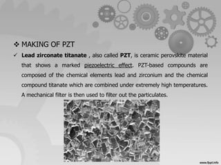
Lead Zirconate Titanate (PZT) is a ceramic material made of lead (Pb),
oxygen (O) and titanium (Ti) or zirconium (Zr).
Chemical formula: Pb[ZrxTi1-x]O3; x = 0,52
The atoms are arranged in a cubical structure.](https://image.slidesharecdn.com/materialtechnology-141113063929-conversion-gate02/85/Material-technology-Newly-develpoed-engineering-materials-4-320.jpg)


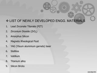
This document discusses several newly developed engineering materials including lead zirconate titanate (PZT), zirconium dioxide (ZrO2), amorphous silicon, and magneto rheological fluid. PZT is a piezoelectric ceramic used in sensors and actuators due to its ability to generate voltage or change shape with electric fields or temperature changes. ZrO2 is a ceramic material that can be stabilized in different crystal phases for uses like thermal barriers or insulators. Amorphous silicon lacks a crystalline structure but can be used in devices like thin-film transistors and solar cells when hydrogenated. Magneto rheological fluid increases viscosity when exposed to magnetic fields, allowing controllable damp