Downloaded 19 times
![Visit-www.engineering-grs.com
SAM(t)=Ac[1+ Am/ Ac cos(2П fmt) ] cos(2П fct)
SAM (t)=Ac[1+m(t)]cos(2П fct)
• The modulation index k is given as the ratio of max
amplitude of the modulating signal and the max amplitude of
the carrier signal. It is also sometime expressed as %
modulation
• K = Am/Ac
• Ac[1+ Am/ Ac cos(2П fmt) ] cos(2П fct)](https://image.slidesharecdn.com/1unit-130913001906-phpapp02/85/1-unit-4-320.jpg)
![Visit-www.engineering-grs.com
= Ac cos(2П fct) +Am/2 cos(2П (Fc+ Fm)t)+ Am/2
cos(2П (Fc- Fm)t)
• The modulated signal has a carrier freq, and upper and lower
side bands.
• SAM(t)=Ac[1+m(t)]cos(2П fct)
• The power = Ac2/2+Am2/4+Am2/4
SAM(f)=1/2Ac[δ(f-fc)+M(f-fc)+ δ(f+fc)+M(f+fc)]
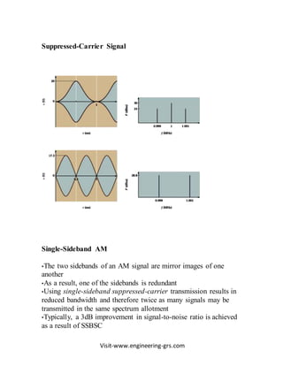
AM Characteristics
• AM is a nonlinear process
• Sum and difference frequencies are created that carry the
information.
Full-Carrier AM: Time Domain
•Modulation Index - The ratio between the amplitudes between the
amplitudes of the modulating signal and carrier, expressed by the
equation:
m = Em/Ec](https://image.slidesharecdn.com/1unit-130913001906-phpapp02/85/1-unit-5-320.jpg)
![Visit-www.engineering-grs.com
Bandwidth
•Signal bandwidth is an important characteristic of any modulation
scheme
•In general, a narrow bandwidth is desirable
•Bandwidth is calculated by:
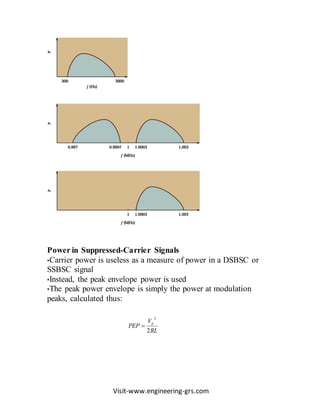
Power Relationships
•Power in a transmitter is important, but the most important power
measurement is that of the portion that transmits the information
•AM carriers remain unchanged with modulation and therefore are
wasteful
•Power in an AM transmitter is calculated according to the formula
at the right.
Pt Pc 1
m2
2
• The total power in an AM signal is
PAM= (½)Ac2 [1+2 <m(t)> + <m2(t)>]
Where <> represents the average value.
• If the modulating signal is m(t)=kcos(2Πfmt),then total
power is
mFB 2](https://image.slidesharecdn.com/1unit-130913001906-phpapp02/85/1-unit-9-320.jpg)
![Visit-www.engineering-grs.com
PAM= (½)Ac2[1+Pm]=Pc[1+(k2/2)]
Where Pc=Ac2/2 is the power in the carrier signal.
Pm=<m2(t)> is the power in the modulating signal.
and k is the modulation index.
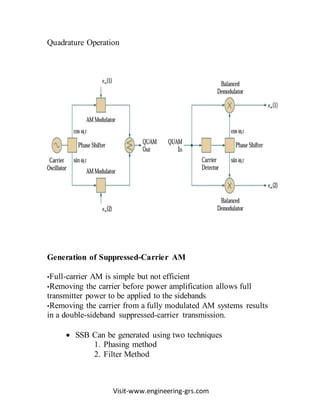
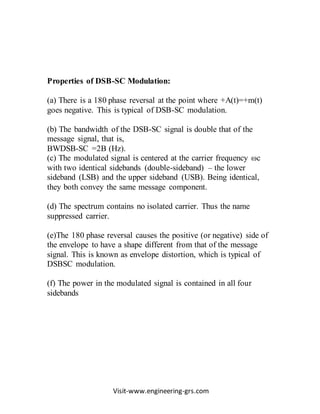
Quadrature AM and AM Stereo
•Two carriers generated at the same frequency but 90º out of phase
with each other allow transmission of two separate signals.
•This approach is known as Quadrature AM (QUAM or QAM)
•Recovery of the two signals is accomplished by synchronous
detection by two balanced modulator](https://image.slidesharecdn.com/1unit-130913001906-phpapp02/85/1-unit-10-320.jpg)
![Visit-www.engineering-grs.com
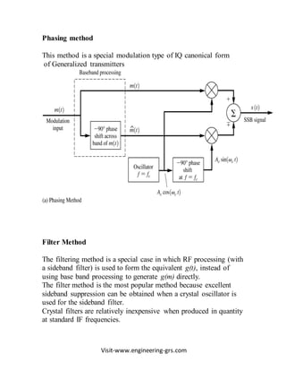
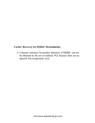
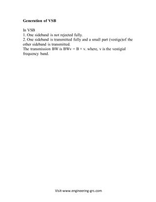
DSBSC and SSB Transmission
Ring Modulator
The DSB-SC can be generated using either the balanced
modulator or the ‗ring-modulator‘.
The balanced modulator uses two identical AM generators
along with an adder.
The two amplitude modulators have a common carrier
with one of them modulating the input message , and the
other modulating the inverted message .
Generation of AM is not simple, and to have two AM
generators with identical operating conditions is extremely
difficult.
]](https://image.slidesharecdn.com/1unit-130913001906-phpapp02/85/1-unit-15-320.jpg)
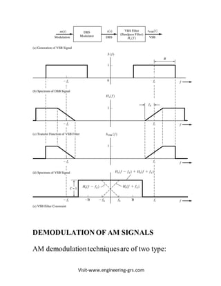
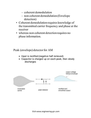
![Visit-www.engineering-grs.com
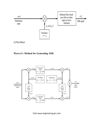
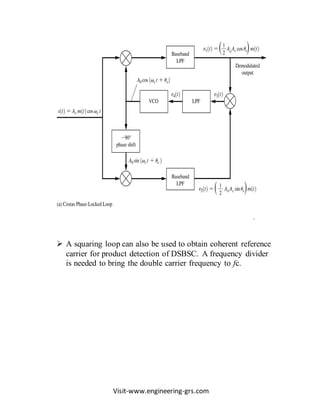
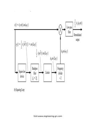
Product Detector:
Coherent demodulator
• It is a down converter circuit which converts the input band
pass signal to a base band signal
• If the input to the product detector is an AM signal of the
form R(t)cos(2Πfct+θr),the output of the multiplier can be
expressed as
v1(t)=R(t) cos(2Πfct+θr)A0 cos(2Πfct+θ0)
• where fc is the oscillator carrier frequency, and θr and θ0 are
the
• received signal phase and oscillator phases respectively.
• v1(t)=1/2 A0 R(t)cos(θr - θ0)+ 1/2 A0
R(t)cos[2Π2fct+θr+θ0]
• The output obtained after passing through a LPF is
Vout(t)=1/2 A0 R(t)cos(θr - θ0)=KR(t)
• Where K is a gain constant](https://image.slidesharecdn.com/1unit-130913001906-phpapp02/85/1-unit-25-320.jpg)

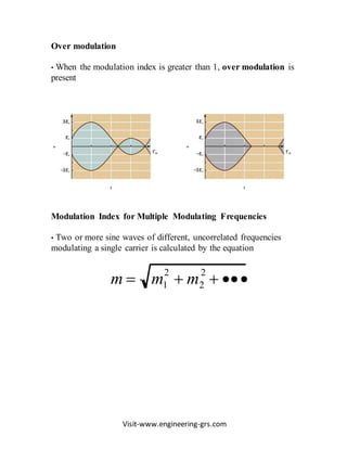
This document provides an overview of amplitude modulation (AM) systems. It discusses why modulation is used, describes the basic AM process of varying a carrier's amplitude based on a message signal, and presents the mathematical representation of an AM wave. It also covers generation and demodulation of AM signals, including full-carrier AM in the time and frequency domains, bandwidth, power relationships, and suppression of the carrier to create double-sideband suppressed-carrier or single-sideband signals. Demodulation techniques like envelope detection and product detection are also summarized.


![Getting Started with Apache Spark: Big Data Made Simple [Free Meetup]](https://cdn.slidesharecdn.com/ss_thumbnails/apachesparkgettingstarted-260203175547-8361bcc3-thumbnail.jpg?width=640&height=640&fit=bounds)


