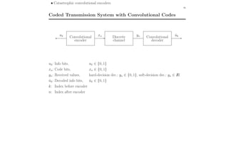
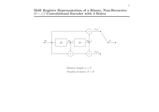
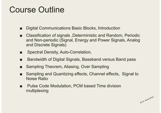
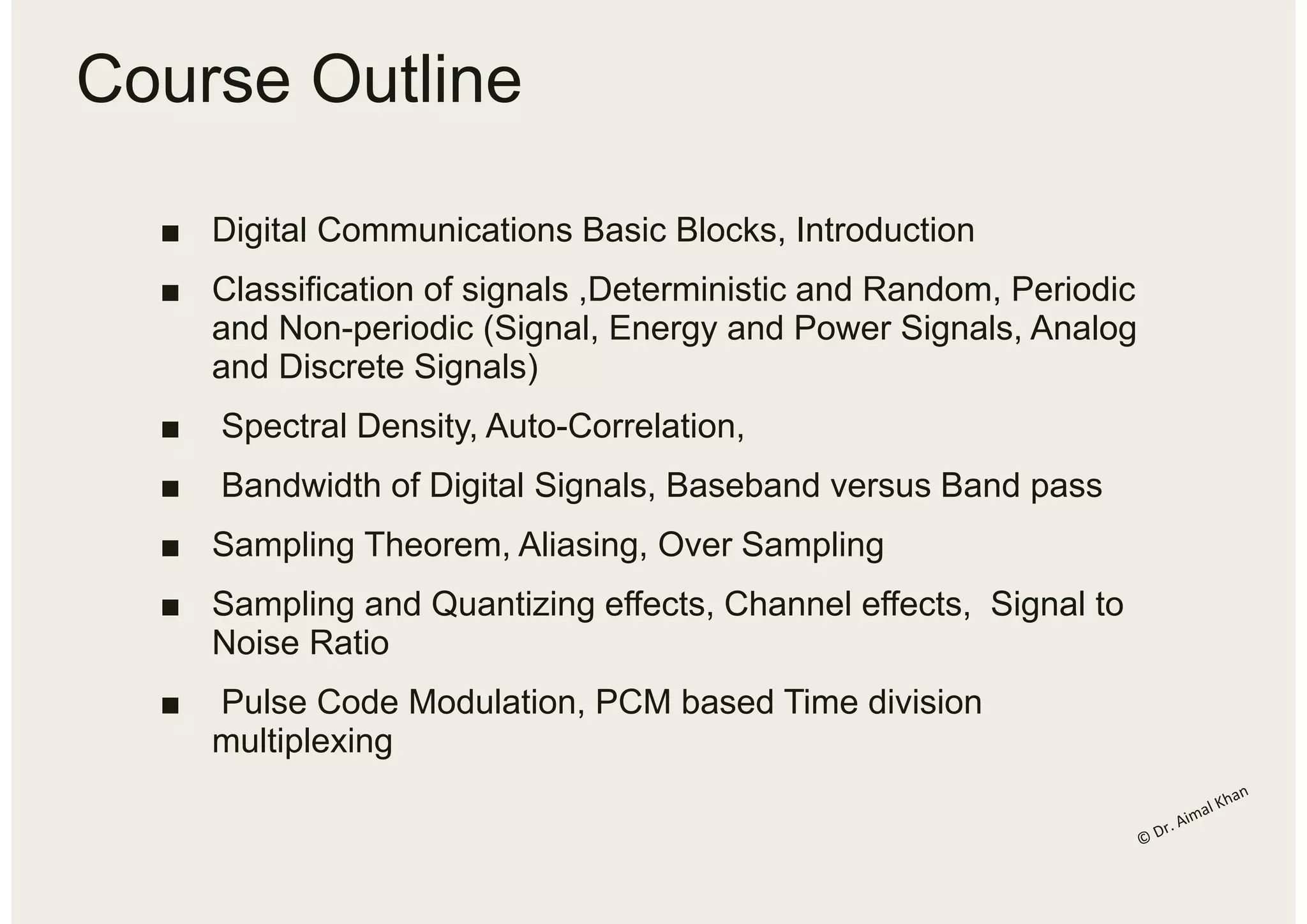
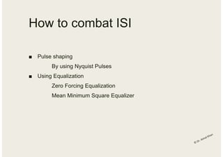
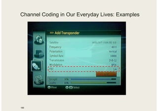
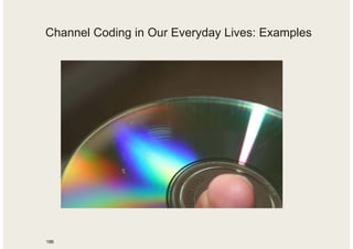
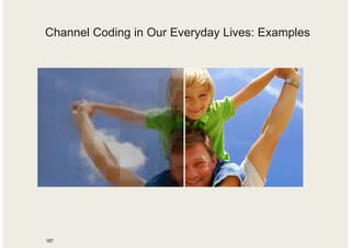
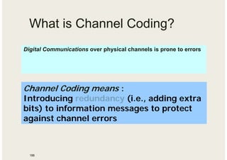
This course outline covers topics in digital communications including basic blocks, signal classification, spectral density, sampling theory, pulse code modulation, quantization, error performance, and detection techniques. Key concepts that will be discussed are bandwidth calculation, inter-symbol interference, eye diagrams, pulse shaping, equalization, channel coding, and convolutional codes.
![• Cyclic block codes, generator polynomial, parity check polynomial
16
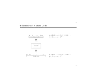
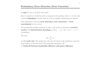
Definition of Block Codes
We denote a sequence u := [u0, u1, . . . , uk−1] of k info symbols as an info word.
The info symbols ui, i = 0, 1, . . . k − 1, are defined over the alphabet {0, 1, . . . , q − 1},
where q is the number of elements (“cardinality”) of the symbol alphabet.
Definition (block code): An (n, k)q block encoder maps an info word
u = [u0, u1, . . . , uk−1] of length k onto a code word x := [x0, x1, . . . , xn−1]
of length n, where n > k.
The code symbols xi, i = 0, 1, . . . , n − 1, are assumed to be within the same alphabet
{0, 1, . . . , q − 1}.
The assignment of code words with respect to the info words is
• unambiguous and reversible: For each code word there is exactly one info word
• time invariant: The mapping rule does not change in time
• memoryless: Each info word effects only one code word](https://image.slidesharecdn.com/lastlecture1-200121064216/85/Basics-of-channel-coding-17-320.jpg)
![19
Systematic Codes
Definition (systematic code): A code is called systematic, if the mapping between
info symbols and code symbols is such that the info symbols are explicitly contained in
the code words.
The n − k remaining symbols are called parity check symbols
(q = 2: parity check bits).
Example 1: (3, 2)2 single parity check (SPC) code:
(q = 2, i.e., one symbol corresponds to one bit)
Info word u = [u0, u1] Code word x = [x0, x1, x2]
[00] [000]
[01] [011]
[10] [101]
[11] [110]
Parity check equation: u0 ⊕ u1 ⊕ x2 = 0 (⊕: modulo-q addition)
Code: C = {[000], [011], [101], [110]}
20](https://image.slidesharecdn.com/lastlecture1-200121064216/85/Basics-of-channel-coding-20-320.jpg)