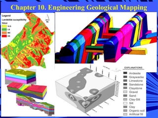
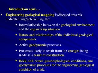
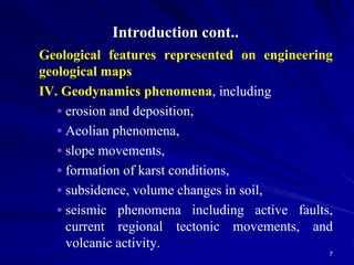
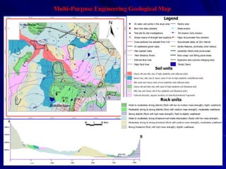
Chapter 10. Engineering Geological Mapping
1
Chapter 10. Engineering Geological
Mapping
10.1 Introduction
10.2 Classifications of Rocks and Soils for
Engineering Purposes
10.3 Types of Engineering Geological Maps
10.4 Data Presentation on Engineering Geological
Maps
10.5 Geological Information on Engineering
Geological Maps
3
Introduction
• Engineer Geologic Mapping (EGM) is a guide to the principles,
concepts, methods, and practices involved in geological mapping,
as well as the applications of geology in engineering.
• Engineering geological maps provide basic information for the:
 Planning of land use.
 Planning, design, construction and maintenance of civil
and mining engineering works.
 Environmental planning and management.
4
Introduction cont.…
• Engineering geological mapping is directed towards
understanding/determining the:
 Interrelationship between the geological environment
and the engineering situation.
 Nature and relationships of the individual geological
components.
 Active geodynamic processes.
 Processes likely to result from the changes being
made as a result of construction.
 Rock, soil, water, geomorphological conditions, and
geodynamic processes for the engineering geological
condition of a site.
Introduction cont.…
Geological mapping vs. EGM
Geological mapping
 Often the base layer is a topographic map
 Distribution of bedrock and superficial deposits
 Age of the rock
 Lithology and structure
 Any major tectonic features
EGM
 Properties of soils and rocks
 Nature and distribution of geodynamic processes
 Hydrogeology
6
Introduction cont..
• Geological features represented on engineering geological maps are:
i. The character of the rocks and soils, including their
 distribution,
 stratigraphical and structural arrangement,
 age, genesis, lithology, physical state, and
 their physical and mechanical properties.
ii. Hydrogeological conditions, including the
 distribution of water-bearing soils and rocks,
 zones of saturated open discontinuities,
 depth to water table and its range of fluctuations,
 regions of confined water and piezometic levels,
 storage coefficients,
 direction of flow, springs, rivers and lakes and
 the limits and occurrence interval of flooding,
 pH, salinity, corrosiveness.
iii.Geomorphological conditions, including
 surface topography and
 important elements of the landscape.
Introduction cont..
Geological features represented on engineering
geological maps
IV. Geodynamics phenomena, including
 erosion and deposition,
 Aeolian phenomena,
 slope movements,
 formation of karst conditions,
 subsidence, volume changes in soil,
 seismic phenomena including active faults,
current regional tectonic movements, and
volcanic activity.
7
Boundaries of rock & soil units shown on engineering geological
maps of various scales should delimit rock and soil unit which
sized by a certain degree of homogeneity in basic engineering
geological properties.
Selection of those geological features of rocks and soils which are
closely related to physical properties such as: strength,
deformability, durability, and permeability are important in
engineering geology.
Because of lack of regional data on the variability of engineering
properties of rocks & soils
Neither have suitable methods and techniques been developed for
determining them in sufficient quantity, over large area,
quantitatively, quickly and cheaply.
2/17/2020 8
Principles of classification of rocks & soils for
engineering geological mapping
It is for this reason we use those geological properties
which best indicate physical or engineering geological
characteristics.
These are:
1. Mineralogical composition closely related to specific
gravity, atterberg limits & plasticity index;
2. Textural and structural characteristics, such as
particle size distribution, related to unit weight,
porosity
3. Moisture content, saturation moisture content,
consistency, degree of weathering and alteration and
jointing, related to the physical state of soils and
rocks and indicating, strength properties, deformation
characteristics, permeability and durability
2/17/2020 9
 Classification of rocks and soils on engineering
geological maps should be based on:
– The principle that the physical or engineering geological
properties of a rock in its present state are dependent on
the combined effects of mode of origin, diagenetic,
metamorphic and tectonic history, & weathering
processes.
– This principle of classification makes it possible not
only to determine the reasons for the lithological &
physical characteristic of soils & rocks, but also for their
spatial distribution.
– The use of many individual rock samples, field
observations and measurements to delineate uniform
and continuous rock units is important.
2/17/2020 10
Based on lithology and mode of origin the following
classification is suggested:
1. Engineering geological type (ET)
2. Lithological type (LT)
3. Lithological complex (LC)
4. Lithological suite (LS)
There is different degree of homogeneity for each unit.
 ET: high degree of homogeneity, uniform in lithological character and
physical state. (large scale maps)
 LT: homogenous throughout in composition, texture and structure. But
not usually uniform in physical state. A general idea of engineering
properties with a range of values can be presented. (large scale maps)
 LC:genetically related lithological types developed under specific palaeo-
geographical & geo-tectonic conditions. Spatial arrangement of
lithological types is uniform and distinctive for that complex, but a LC is
not necessarily uniform in either litholoigcal character or physical state,
only general behaviour of the whole LC.
 LS:comprises many lithological complexes that developed under
generally similar palaeo-geographical and tectonic conditions.
2/17/2020 11
LC
Mapping of rocks and soils for engineering purposes
In general boundaries of rock units could be expected to
follow lithological boundaries, but the engineering
property boundaries may have no relation to either
geological structure or to stratigraphical boundaries.
Selection of an appropriate method for drawing
boundaries to mapping units in the field depends on the
purpose for which the mapping is being undertaken.
Purpose dictates scale & scale will define the basic
taxonomic or mapping unit
LS, LC, LT or ET
2/17/2020 12
 There are suitable methods for mapping the boundaries
of each of the units:
A. LS: interpretation of existing geological map;
reconnaissance mapping; photo-geology.
B. LC: areal mapping with facial analysis to group
together genetically related lithological types.
C. LT: detailed areal mapping and petrographic
investigation.
D. ET: detailed investigation of the physical state of the
rock or soil mass within a mapped lithological type.2/17/2020 13
Special techniques for engineering geological mapping
1. Photo-geology
2. Geophysical methods
3. Boring and sampling techniques
4. Laboratory and in situ testing
• Laboratory tests
 Basic properties of rocks and soils
 Particle size analysis, LL & PL, density, specific gravity, etc
 Physical properties: consistency, cohesion & angle of
internal friction, compressibility, permeability, compressive
strength, tensile strength, compaction, etc.
• In situ testing
Deformation characteristics of rocks & soils, shear strength,
piezometric pressure,
Pumping in & pumping out tests (permeability test), cone
penetrometer test, SPT, etc
2/17/2020 14
It is classified according to purpose, content and scale.
According to purpose
They may be:
1.Special purpose: providing information either on one specific
aspect of engineering geology, or for one specific purpose.
2.Multipurpose: providing information covering many aspects of
engineering geology for a variety of planning and
engineering purpose.
According to scale
They may be:
1.Large-scale: 1:10,000 and greater
2.Medium-scale: less than 1:10,000 and greater than 1:100,000
3.Small-scale: 1:100,000 and less
2/17/2020
15
Types/Classification of Engineering
Geological maps
According to content
They may be:
1. Analytical maps: they are giving details or evaluating individual
components of the geological environment. E.g map of weathering
grades, jointing map, seismic hazard map.
2. Comprehensive maps: these are of two kinds:
• Maps of engineering geological conditions depicting all the
principal components of the engineering geological environment.
• Maps of engineering geological zoning, evaluating and classifying
individual territorial units on the basis of the uniformity of their
engineering geological conditions. They can be combined together
on small scale maps.
3. Auxiliary maps: These present factual data, for example,
documentation maps, structural contour maps, etc.
4. Complementary maps: include geological, tectonic,
geomorphological, pedological, geophysical and hydrogeological
maps.
2/17/2020 16
17
Data Presentation on Engineering Geological Maps
Techniques used in the presentation of data on multi-purpose comprehensive map
are as following.
(a) 3-Dimensional representation of maps
 Because engineering structures have an influence on the sub-surface,
and often extend below the ground surface or are constructed below the
surface, 3D representation on engineering geological maps is desirable.
 Where surficial deposits overlie bedrock it is generally desirable to show
the depth and character of the bedrock surface.
 On small-scale maps, 3D information can be given only at points by
symbols; in more detailed maps the bedrock surface and details of the
surfacial deposits should, if possible, be shown by any one of several
methods:
 bedrock contours,
 point logs of boring,
 cross-sections,
 isometric diagrams, or
 No method used should overcrowd the map to the point of illegibility.3D Engineering Geology for ground structures: from top to bottom.
18
(b) Engineering Geological Cross-sections
 Engineering geological cross-sections are a necessary adjunct to all
main types of engineering geological maps.
 The number and direction of the cross-sections are chosen, taking
into account geomorphology and geological structure, to illustrate the
relationship between the components of the engineering geological
conditions.
 The horizontal scale of cross-sections should be equal to, or larger
than, the scale of the map.
 Vertical scale is chosen so that it is possible to show the extent and
character of the uppermost rock and soil units.
 The depth to which the cross-section is drawn should be directly
related to the depth of available boreholes and other excavations.
 All information presented on the map should also be shown on the
cross-sections, for example, hydrogeological conditions, engineering
geological zoning, the results of geodynamic processes and
engineering properties of all rock and soil units.
 The degree of detail on the cross-section will correspond with the
detail shown on the map.
Multi-Purpose Engineering Geological Map
20
(c) Documentation Maps
 A documentation map provides a record of sources of information
used in compiling an engineering geological map.
 The documentation map should be drawn at the same scale as the
associated engineering geological map, and if there is no danger of
overcoming the map with symbols, the two maps may be combined
in one sheet.
 The information recorded on the documentation map includes, for
example, symbols showing:
 The position, depth and type of individual boreholes.
 Observed or investigated exposures, pits, quarries and
other excavations.
 Wells and springs.
 Locations of sites used for geophysical investigations and
other in-situ tests, sampling points, etc.
 The legend on the documentation map sheet should explain all
symbols used.
 Standard symbols should be used where they are available.
21
(d) Explanation and legend
 The explanation or legend on the engineering
geological map provides a guide to the symbols,
colors and patterns used in producing the map.
 In addition, summary accounts may be given, for
example of rock or soil properties,
hydrogeological conditions, geodynamic
processes, and the evaluation of individual zoning
units.
22
Geological Information on Engineering Geological Maps
(a) Principles of classification of rocks and soils for engineering geological
mapping
 The boundaries of rock and soil units shown on engineering geological
map of various scales should delimit rock and soil units which are
characterized by a certain degree of homogeneity in basic engineering
geological properties.
 The main problem in engineering geological mapping is the selection of
those geological features of rocks and soils which are closely related to
physical properties, such as strength, deformability, durability, which are
important in engineering geology.
 Challenges are due to:
 Lack of regional data on the variability of engineering
properties of rocks and soils.
 Lack of well developed techniques for determining the
engineering properties of rocks and soils in sufficient quantity,
over large areas, quantitatively, quickly and cheaply.
 We have to use those geological properties which best indicate
physical or engineering geological characteristics.
23
 Geological properties which best indicate physical or engineering
geological characteristics include the following
a. Mineralogical composition closely related to specific gravity,
Atterberg limits and plasticity index.
b. Textural and structural characteristics, such as particle size
distribution, related to unit weight, porosity.
c. Moisture content, saturation moisture content, consistency, degree of
weathering and alteration, and jointing, related to the physical state of
soils and rocks indicating strength properties, deformation
characteristics, permeability and durability.
 Classification of rocks and soils on engineering geological map
should be based on the principle that the physical or engineering
geological properties of a rock in its present state are dependent on the
combined effects of:
a. Mode of origin.
b. Subsequent digenetic, metamorphic and tectonic
history.
c. Weathering process.
 This principle of classification makes it possible not only to determine the
reasons for the lithological and physical characteristics of soils and rock, but also
for their spatial distribution.
24
 This is the basic principle of engineering geological mapping as of
geological mapping, and implies not only the classification of individual
rock samples but also the use of many individual rock samples, field
observations and measurements to delineate uniform and continuous rock
units.
(b) Hydrogeological Conditions
 Hydrogeological conditions affect landslides, planning, site selection and
the cost, durability and even the safety of structures.
 Ground and surface waters play a prominent part in such geodynamic
processes as:
 Weathering.
 Slope movements.
 Mechanical and chemical suffusion.
 The development of karst conditions.
 Volume changes by shrinking and swelling, and collapse in
loessic soils.
 Groundwater may influence excavation and construction methods by:
 Flowing into excavations,
 Producing seepage forces and uplift pressure, and
 Its corrosive action.
25
 In engineering geological mapping, therefore, the following important
information on hydrogeological conditions should be evaluated and
represented on maps:
 Distribution of surface and sub-surface water.
 Infiltration conditions.
 Water content.
 Direction and velocity of groundwater flow.
 Springs and seepages from individual water-bearing horizons.
 Depth to water table and its range of fluctuations.
 Regions of confined water and piezometric levels.
 Hydrochemical properties such as pH, salinity, corrosiveness.
 Presence of bacterial or other pollutants.
(c) Geomorphological conditions
 Geomorphological mapping is helpful in explaining the recent history of
development of the landscape such as the formation of valleys, terraces,
slope configuration and the processes active in the landscape at the
present time.
 It is an essential part of the engineering geological mapping which can be
carried out quickly and cheaply and is often a decisive factor in planning an
engineering geological investigation.
26
 Evaluation of geomoprhological conditions in engineering geological
mapping should include:
 Relationship between surface conditions and the geological
setting.
 Origin, development and age of individual geomorphological
elements.
 Influence of geomorphological conditions on hydrology and
geodynamic processes.
 Prediction of impending development of geomorphological
features such as the lateral erosion of river banks, movement of
dunes, collapse in karst or undermined areas.
(d) Evaluation of Geodynamic phenomena
 Geodynamic phenomena are those geological features of the environment
resulting from geological processes active at the present time. The geological
features include those due to:
i. Erosion and deposition.
ii. Aeolian processes.
iii. Slope movements,
iv. Permafrost.
v. Formation of karst conditions.
vi. Suffusion.
vii. Volume changes in soil.
viii.Seismic and volcanic activity.
27
2.6 GIS applications in engineering geological
mapping
Reading assignment:
What is GIS?
What is RS?
What type of information could be obtained from RS?
Why GIS is so relevant in Engineering Geological Mapping?
28
Spatial landslide
probability map of
100-year
return-period
rainfall intensity.
29
30
Example of a computer generated three-dimensional solid model of the rock mass
in which the Chuquicamataopen pit copper mine in northern Chile is being mined.
31
Isometric view of the three-dimensional numerical model of the underground
powerhouse cavern and transformer gallery of the Nathpa Jhakri Hydroelectric
Project.
32
3D Block-Diagram subsurface Geological - Geotechnical modeling
Lecture 10p

Lecture 10p

  • 1.
    Chapter 10. EngineeringGeological Mapping 1
  • 2.
    Chapter 10. EngineeringGeological Mapping 10.1 Introduction 10.2 Classifications of Rocks and Soils for Engineering Purposes 10.3 Types of Engineering Geological Maps 10.4 Data Presentation on Engineering Geological Maps 10.5 Geological Information on Engineering Geological Maps
  • 3.
    3 Introduction • Engineer GeologicMapping (EGM) is a guide to the principles, concepts, methods, and practices involved in geological mapping, as well as the applications of geology in engineering. • Engineering geological maps provide basic information for the:  Planning of land use.  Planning, design, construction and maintenance of civil and mining engineering works.  Environmental planning and management.
  • 4.
    4 Introduction cont.… • Engineeringgeological mapping is directed towards understanding/determining the:  Interrelationship between the geological environment and the engineering situation.  Nature and relationships of the individual geological components.  Active geodynamic processes.  Processes likely to result from the changes being made as a result of construction.  Rock, soil, water, geomorphological conditions, and geodynamic processes for the engineering geological condition of a site.
  • 5.
    Introduction cont.… Geological mappingvs. EGM Geological mapping  Often the base layer is a topographic map  Distribution of bedrock and superficial deposits  Age of the rock  Lithology and structure  Any major tectonic features EGM  Properties of soils and rocks  Nature and distribution of geodynamic processes  Hydrogeology
  • 6.
    6 Introduction cont.. • Geologicalfeatures represented on engineering geological maps are: i. The character of the rocks and soils, including their  distribution,  stratigraphical and structural arrangement,  age, genesis, lithology, physical state, and  their physical and mechanical properties. ii. Hydrogeological conditions, including the  distribution of water-bearing soils and rocks,  zones of saturated open discontinuities,  depth to water table and its range of fluctuations,  regions of confined water and piezometic levels,  storage coefficients,  direction of flow, springs, rivers and lakes and  the limits and occurrence interval of flooding,  pH, salinity, corrosiveness. iii.Geomorphological conditions, including  surface topography and  important elements of the landscape.
  • 7.
    Introduction cont.. Geological featuresrepresented on engineering geological maps IV. Geodynamics phenomena, including  erosion and deposition,  Aeolian phenomena,  slope movements,  formation of karst conditions,  subsidence, volume changes in soil,  seismic phenomena including active faults, current regional tectonic movements, and volcanic activity. 7
  • 8.
    Boundaries of rock& soil units shown on engineering geological maps of various scales should delimit rock and soil unit which sized by a certain degree of homogeneity in basic engineering geological properties. Selection of those geological features of rocks and soils which are closely related to physical properties such as: strength, deformability, durability, and permeability are important in engineering geology. Because of lack of regional data on the variability of engineering properties of rocks & soils Neither have suitable methods and techniques been developed for determining them in sufficient quantity, over large area, quantitatively, quickly and cheaply. 2/17/2020 8 Principles of classification of rocks & soils for engineering geological mapping
  • 9.
    It is forthis reason we use those geological properties which best indicate physical or engineering geological characteristics. These are: 1. Mineralogical composition closely related to specific gravity, atterberg limits & plasticity index; 2. Textural and structural characteristics, such as particle size distribution, related to unit weight, porosity 3. Moisture content, saturation moisture content, consistency, degree of weathering and alteration and jointing, related to the physical state of soils and rocks and indicating, strength properties, deformation characteristics, permeability and durability 2/17/2020 9
  • 10.
     Classification ofrocks and soils on engineering geological maps should be based on: – The principle that the physical or engineering geological properties of a rock in its present state are dependent on the combined effects of mode of origin, diagenetic, metamorphic and tectonic history, & weathering processes. – This principle of classification makes it possible not only to determine the reasons for the lithological & physical characteristic of soils & rocks, but also for their spatial distribution. – The use of many individual rock samples, field observations and measurements to delineate uniform and continuous rock units is important. 2/17/2020 10
  • 11.
    Based on lithologyand mode of origin the following classification is suggested: 1. Engineering geological type (ET) 2. Lithological type (LT) 3. Lithological complex (LC) 4. Lithological suite (LS) There is different degree of homogeneity for each unit.  ET: high degree of homogeneity, uniform in lithological character and physical state. (large scale maps)  LT: homogenous throughout in composition, texture and structure. But not usually uniform in physical state. A general idea of engineering properties with a range of values can be presented. (large scale maps)  LC:genetically related lithological types developed under specific palaeo- geographical & geo-tectonic conditions. Spatial arrangement of lithological types is uniform and distinctive for that complex, but a LC is not necessarily uniform in either litholoigcal character or physical state, only general behaviour of the whole LC.  LS:comprises many lithological complexes that developed under generally similar palaeo-geographical and tectonic conditions. 2/17/2020 11 LC
  • 12.
    Mapping of rocksand soils for engineering purposes In general boundaries of rock units could be expected to follow lithological boundaries, but the engineering property boundaries may have no relation to either geological structure or to stratigraphical boundaries. Selection of an appropriate method for drawing boundaries to mapping units in the field depends on the purpose for which the mapping is being undertaken. Purpose dictates scale & scale will define the basic taxonomic or mapping unit LS, LC, LT or ET 2/17/2020 12
  • 13.
     There aresuitable methods for mapping the boundaries of each of the units: A. LS: interpretation of existing geological map; reconnaissance mapping; photo-geology. B. LC: areal mapping with facial analysis to group together genetically related lithological types. C. LT: detailed areal mapping and petrographic investigation. D. ET: detailed investigation of the physical state of the rock or soil mass within a mapped lithological type.2/17/2020 13
  • 14.
    Special techniques forengineering geological mapping 1. Photo-geology 2. Geophysical methods 3. Boring and sampling techniques 4. Laboratory and in situ testing • Laboratory tests  Basic properties of rocks and soils  Particle size analysis, LL & PL, density, specific gravity, etc  Physical properties: consistency, cohesion & angle of internal friction, compressibility, permeability, compressive strength, tensile strength, compaction, etc. • In situ testing Deformation characteristics of rocks & soils, shear strength, piezometric pressure, Pumping in & pumping out tests (permeability test), cone penetrometer test, SPT, etc 2/17/2020 14
  • 15.
    It is classifiedaccording to purpose, content and scale. According to purpose They may be: 1.Special purpose: providing information either on one specific aspect of engineering geology, or for one specific purpose. 2.Multipurpose: providing information covering many aspects of engineering geology for a variety of planning and engineering purpose. According to scale They may be: 1.Large-scale: 1:10,000 and greater 2.Medium-scale: less than 1:10,000 and greater than 1:100,000 3.Small-scale: 1:100,000 and less 2/17/2020 15 Types/Classification of Engineering Geological maps
  • 16.
    According to content Theymay be: 1. Analytical maps: they are giving details or evaluating individual components of the geological environment. E.g map of weathering grades, jointing map, seismic hazard map. 2. Comprehensive maps: these are of two kinds: • Maps of engineering geological conditions depicting all the principal components of the engineering geological environment. • Maps of engineering geological zoning, evaluating and classifying individual territorial units on the basis of the uniformity of their engineering geological conditions. They can be combined together on small scale maps. 3. Auxiliary maps: These present factual data, for example, documentation maps, structural contour maps, etc. 4. Complementary maps: include geological, tectonic, geomorphological, pedological, geophysical and hydrogeological maps. 2/17/2020 16
  • 17.
    17 Data Presentation onEngineering Geological Maps Techniques used in the presentation of data on multi-purpose comprehensive map are as following. (a) 3-Dimensional representation of maps  Because engineering structures have an influence on the sub-surface, and often extend below the ground surface or are constructed below the surface, 3D representation on engineering geological maps is desirable.  Where surficial deposits overlie bedrock it is generally desirable to show the depth and character of the bedrock surface.  On small-scale maps, 3D information can be given only at points by symbols; in more detailed maps the bedrock surface and details of the surfacial deposits should, if possible, be shown by any one of several methods:  bedrock contours,  point logs of boring,  cross-sections,  isometric diagrams, or  No method used should overcrowd the map to the point of illegibility.3D Engineering Geology for ground structures: from top to bottom.
  • 18.
    18 (b) Engineering GeologicalCross-sections  Engineering geological cross-sections are a necessary adjunct to all main types of engineering geological maps.  The number and direction of the cross-sections are chosen, taking into account geomorphology and geological structure, to illustrate the relationship between the components of the engineering geological conditions.  The horizontal scale of cross-sections should be equal to, or larger than, the scale of the map.  Vertical scale is chosen so that it is possible to show the extent and character of the uppermost rock and soil units.  The depth to which the cross-section is drawn should be directly related to the depth of available boreholes and other excavations.  All information presented on the map should also be shown on the cross-sections, for example, hydrogeological conditions, engineering geological zoning, the results of geodynamic processes and engineering properties of all rock and soil units.  The degree of detail on the cross-section will correspond with the detail shown on the map.
  • 19.
  • 20.
    20 (c) Documentation Maps A documentation map provides a record of sources of information used in compiling an engineering geological map.  The documentation map should be drawn at the same scale as the associated engineering geological map, and if there is no danger of overcoming the map with symbols, the two maps may be combined in one sheet.  The information recorded on the documentation map includes, for example, symbols showing:  The position, depth and type of individual boreholes.  Observed or investigated exposures, pits, quarries and other excavations.  Wells and springs.  Locations of sites used for geophysical investigations and other in-situ tests, sampling points, etc.  The legend on the documentation map sheet should explain all symbols used.  Standard symbols should be used where they are available.
  • 21.
    21 (d) Explanation andlegend  The explanation or legend on the engineering geological map provides a guide to the symbols, colors and patterns used in producing the map.  In addition, summary accounts may be given, for example of rock or soil properties, hydrogeological conditions, geodynamic processes, and the evaluation of individual zoning units.
  • 22.
    22 Geological Information onEngineering Geological Maps (a) Principles of classification of rocks and soils for engineering geological mapping  The boundaries of rock and soil units shown on engineering geological map of various scales should delimit rock and soil units which are characterized by a certain degree of homogeneity in basic engineering geological properties.  The main problem in engineering geological mapping is the selection of those geological features of rocks and soils which are closely related to physical properties, such as strength, deformability, durability, which are important in engineering geology.  Challenges are due to:  Lack of regional data on the variability of engineering properties of rocks and soils.  Lack of well developed techniques for determining the engineering properties of rocks and soils in sufficient quantity, over large areas, quantitatively, quickly and cheaply.  We have to use those geological properties which best indicate physical or engineering geological characteristics.
  • 23.
    23  Geological propertieswhich best indicate physical or engineering geological characteristics include the following a. Mineralogical composition closely related to specific gravity, Atterberg limits and plasticity index. b. Textural and structural characteristics, such as particle size distribution, related to unit weight, porosity. c. Moisture content, saturation moisture content, consistency, degree of weathering and alteration, and jointing, related to the physical state of soils and rocks indicating strength properties, deformation characteristics, permeability and durability.  Classification of rocks and soils on engineering geological map should be based on the principle that the physical or engineering geological properties of a rock in its present state are dependent on the combined effects of: a. Mode of origin. b. Subsequent digenetic, metamorphic and tectonic history. c. Weathering process.  This principle of classification makes it possible not only to determine the reasons for the lithological and physical characteristics of soils and rock, but also for their spatial distribution.
  • 24.
    24  This isthe basic principle of engineering geological mapping as of geological mapping, and implies not only the classification of individual rock samples but also the use of many individual rock samples, field observations and measurements to delineate uniform and continuous rock units. (b) Hydrogeological Conditions  Hydrogeological conditions affect landslides, planning, site selection and the cost, durability and even the safety of structures.  Ground and surface waters play a prominent part in such geodynamic processes as:  Weathering.  Slope movements.  Mechanical and chemical suffusion.  The development of karst conditions.  Volume changes by shrinking and swelling, and collapse in loessic soils.  Groundwater may influence excavation and construction methods by:  Flowing into excavations,  Producing seepage forces and uplift pressure, and  Its corrosive action.
  • 25.
    25  In engineeringgeological mapping, therefore, the following important information on hydrogeological conditions should be evaluated and represented on maps:  Distribution of surface and sub-surface water.  Infiltration conditions.  Water content.  Direction and velocity of groundwater flow.  Springs and seepages from individual water-bearing horizons.  Depth to water table and its range of fluctuations.  Regions of confined water and piezometric levels.  Hydrochemical properties such as pH, salinity, corrosiveness.  Presence of bacterial or other pollutants. (c) Geomorphological conditions  Geomorphological mapping is helpful in explaining the recent history of development of the landscape such as the formation of valleys, terraces, slope configuration and the processes active in the landscape at the present time.  It is an essential part of the engineering geological mapping which can be carried out quickly and cheaply and is often a decisive factor in planning an engineering geological investigation.
  • 26.
    26  Evaluation ofgeomoprhological conditions in engineering geological mapping should include:  Relationship between surface conditions and the geological setting.  Origin, development and age of individual geomorphological elements.  Influence of geomorphological conditions on hydrology and geodynamic processes.  Prediction of impending development of geomorphological features such as the lateral erosion of river banks, movement of dunes, collapse in karst or undermined areas. (d) Evaluation of Geodynamic phenomena  Geodynamic phenomena are those geological features of the environment resulting from geological processes active at the present time. The geological features include those due to: i. Erosion and deposition. ii. Aeolian processes. iii. Slope movements, iv. Permafrost. v. Formation of karst conditions. vi. Suffusion. vii. Volume changes in soil. viii.Seismic and volcanic activity.
  • 27.
    27 2.6 GIS applicationsin engineering geological mapping Reading assignment: What is GIS? What is RS? What type of information could be obtained from RS? Why GIS is so relevant in Engineering Geological Mapping?
  • 28.
    28 Spatial landslide probability mapof 100-year return-period rainfall intensity.
  • 29.
  • 30.
    30 Example of acomputer generated three-dimensional solid model of the rock mass in which the Chuquicamataopen pit copper mine in northern Chile is being mined.
  • 31.
    31 Isometric view ofthe three-dimensional numerical model of the underground powerhouse cavern and transformer gallery of the Nathpa Jhakri Hydroelectric Project.
  • 32.
    32 3D Block-Diagram subsurfaceGeological - Geotechnical modeling