Download as PDF, PPTX


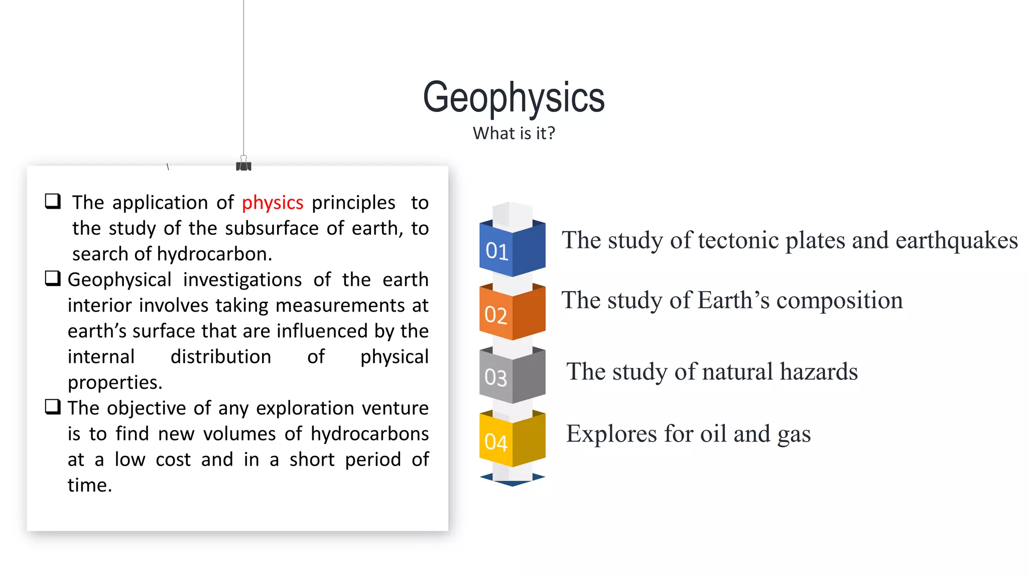


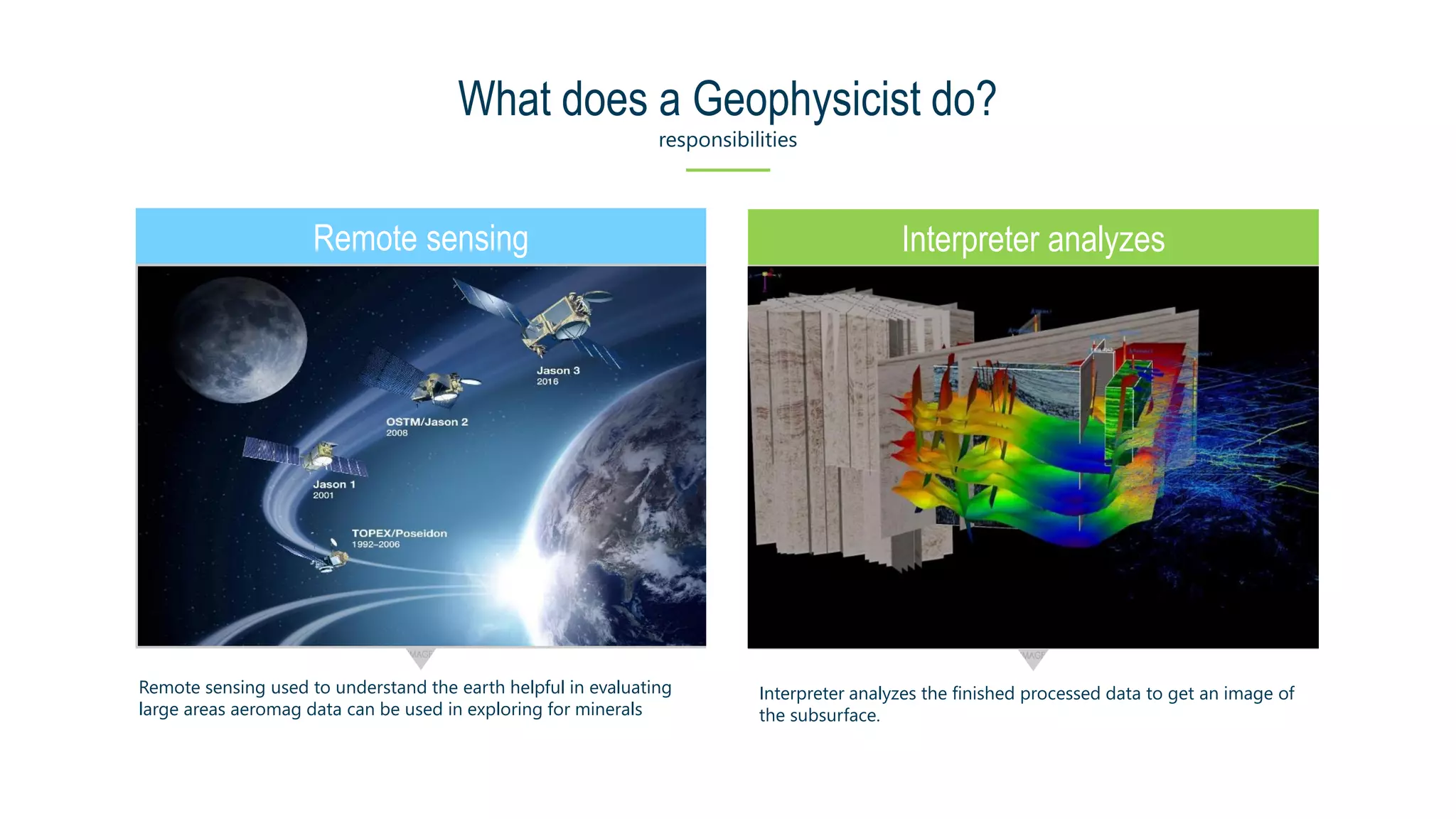


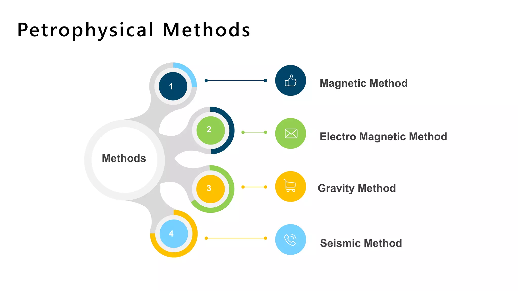

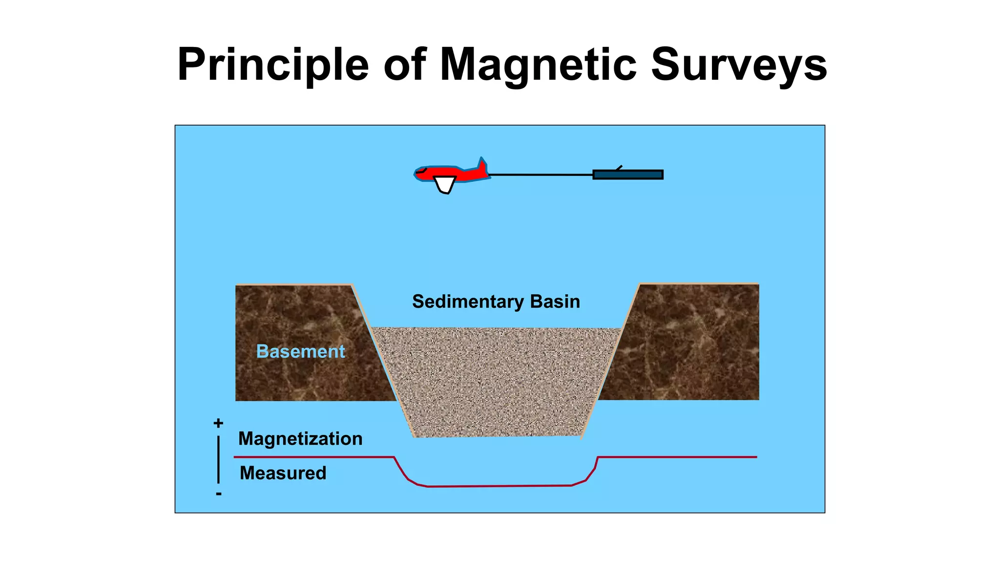


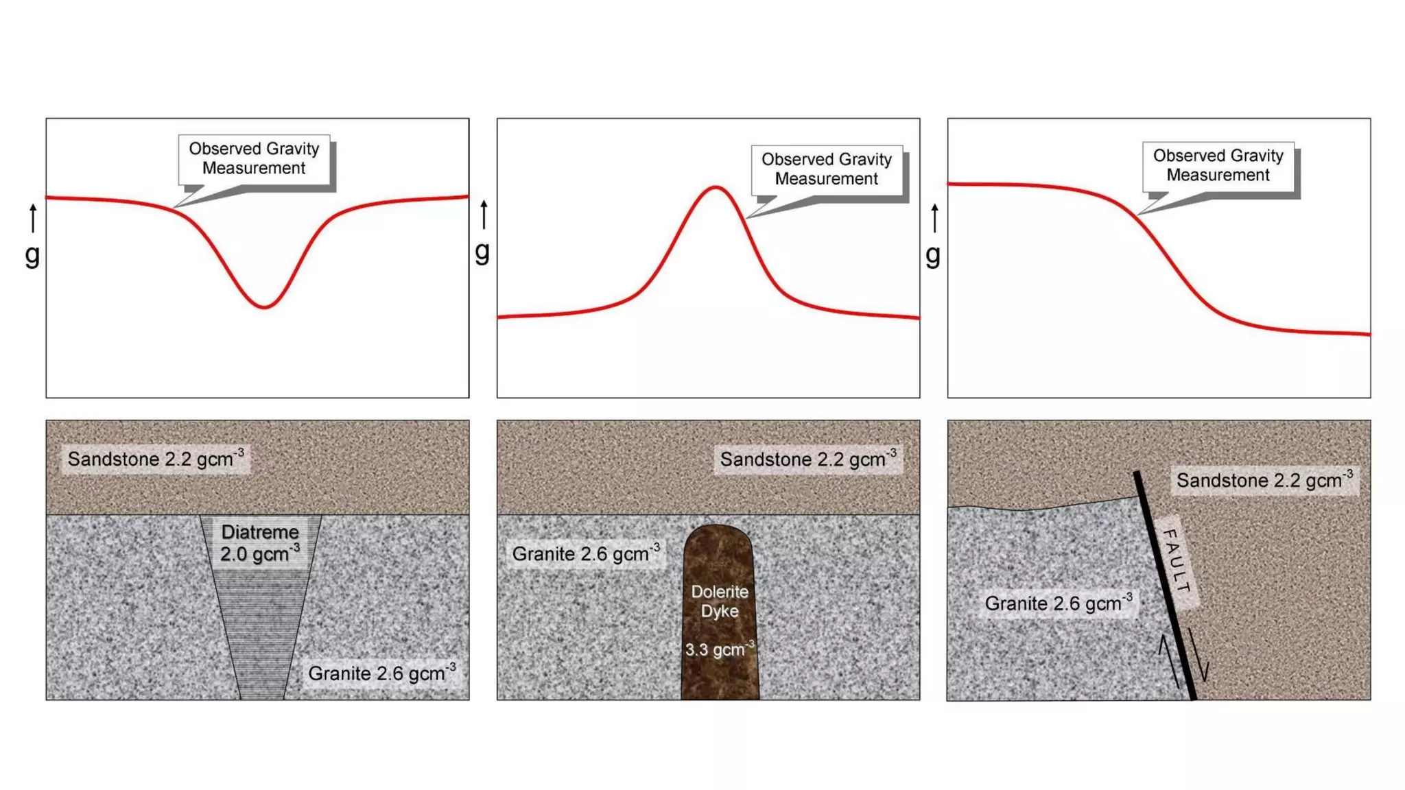
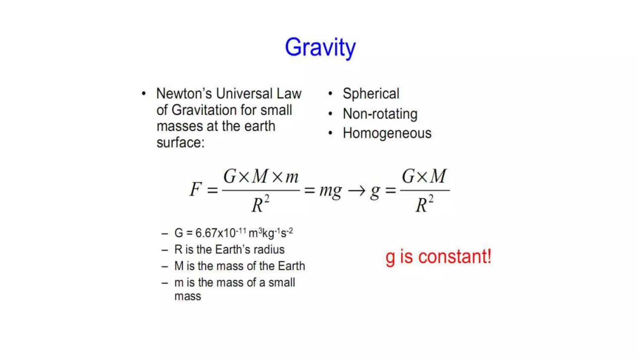


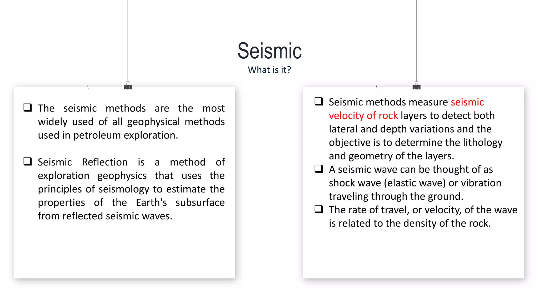
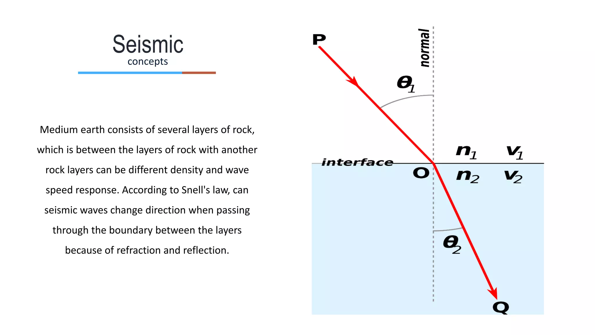


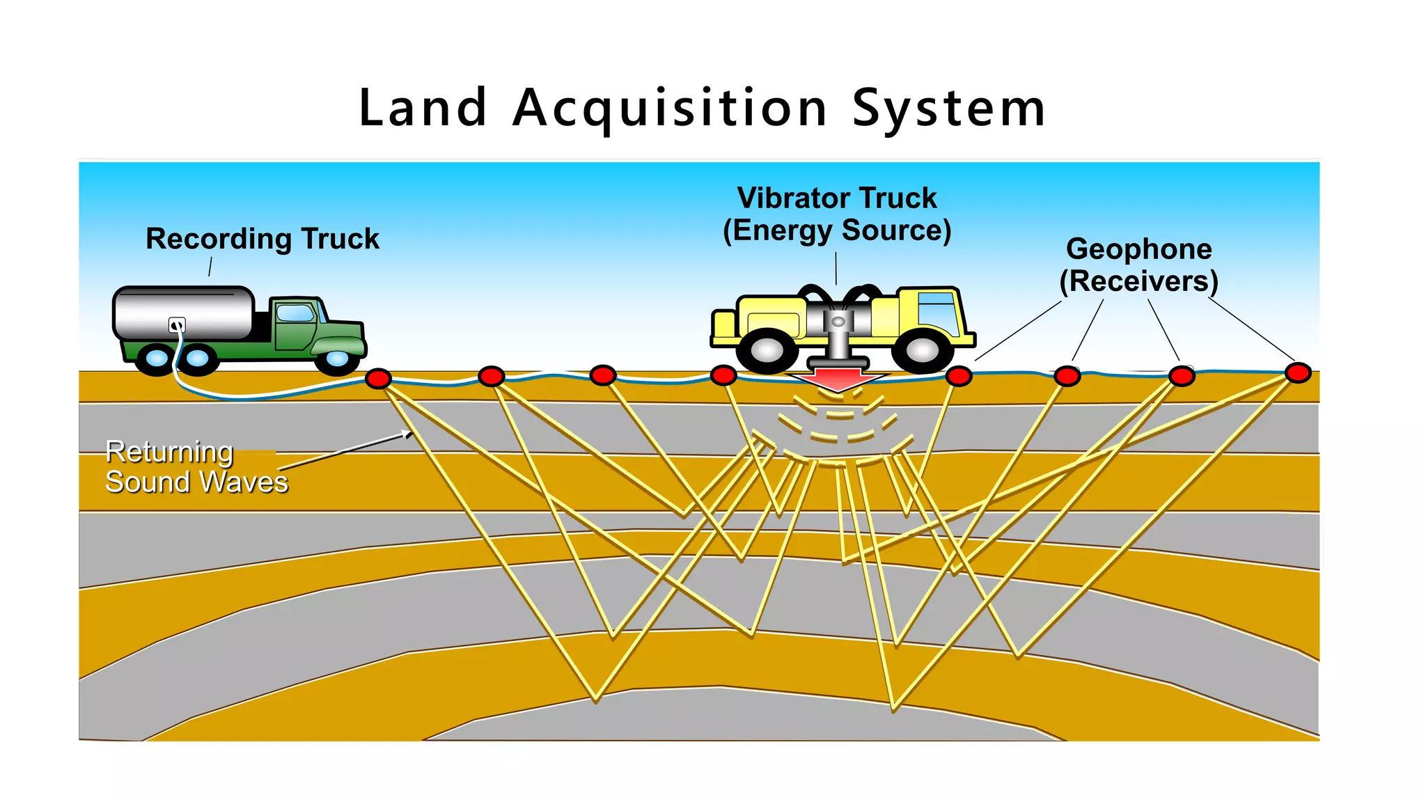


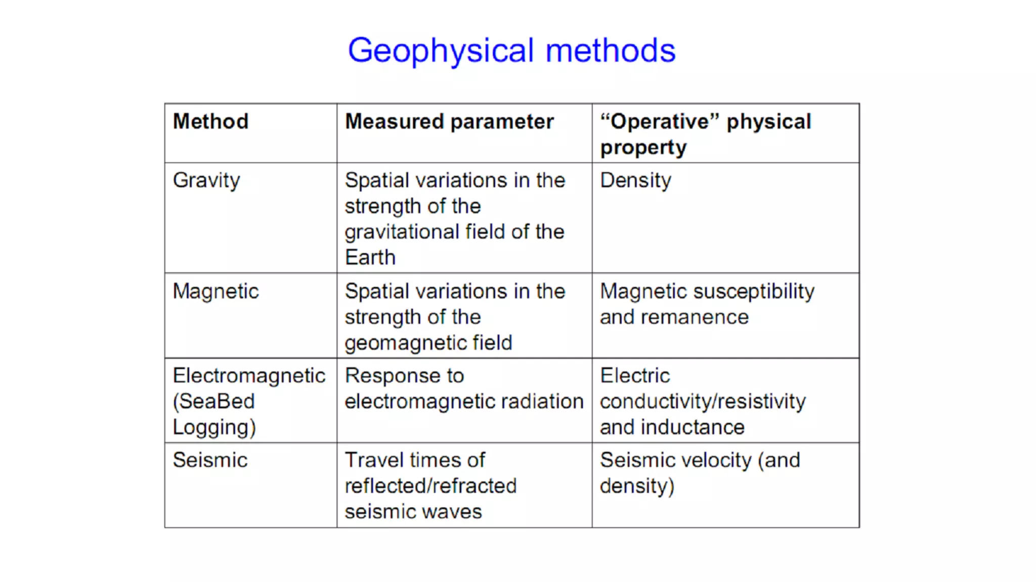
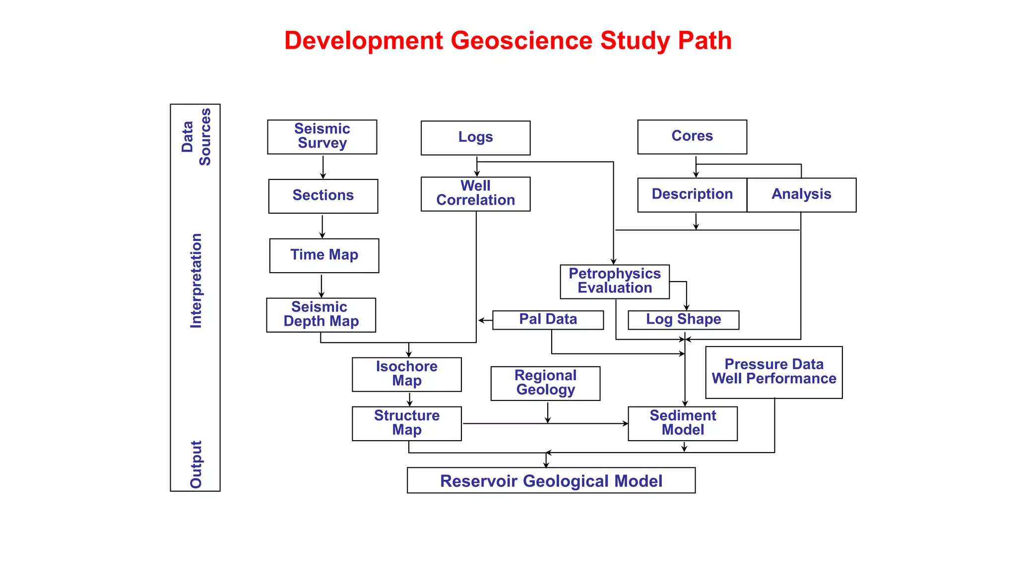

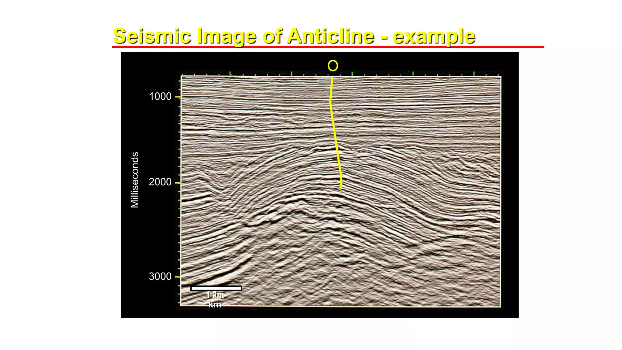


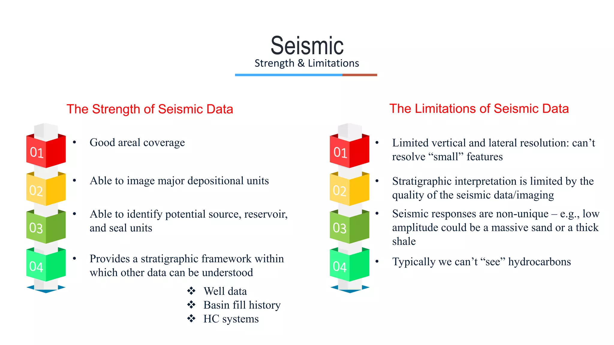


The document discusses the framework and processes involved in oil and gas exploration, covering aspects from field development to geophysical methods such as seismic, magnetic, and gravity surveys. It outlines the roles and responsibilities of geophysicists in environmentally sensitive areas and emphasizes the importance of interpreting geological data to locate hydrocarbons. The document also highlights the strengths and limitations of seismic data in identifying potential reservoirs and understanding subsurface geology.


