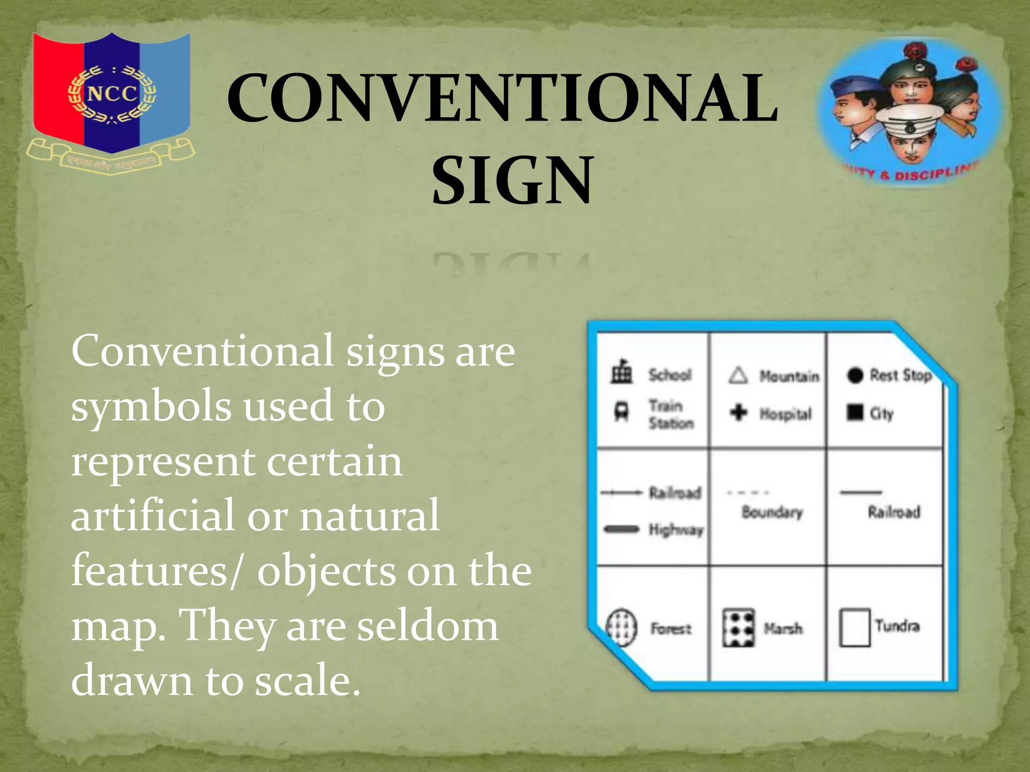
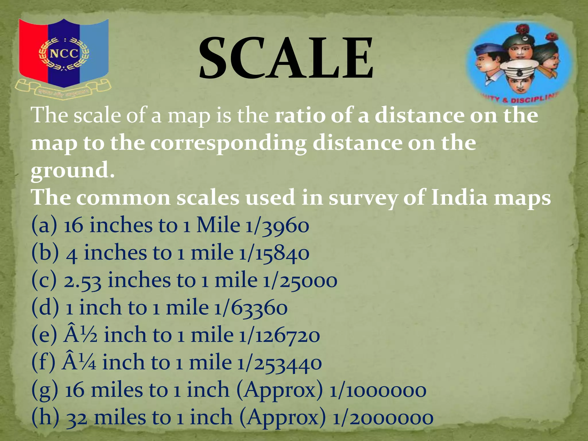
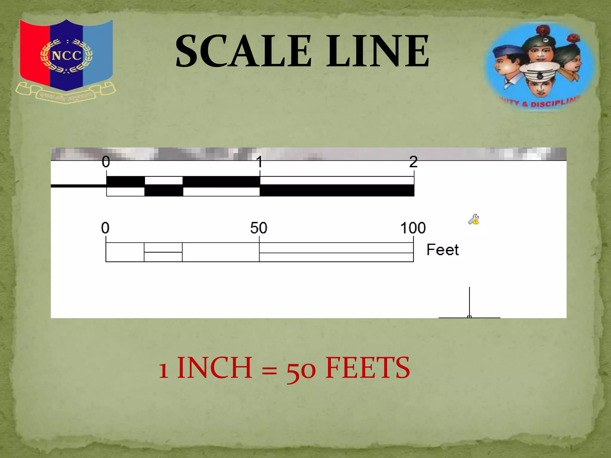
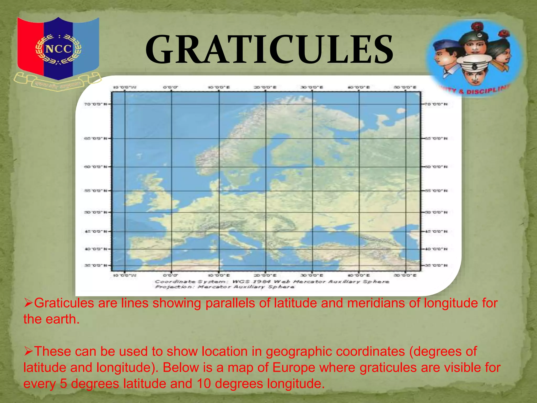
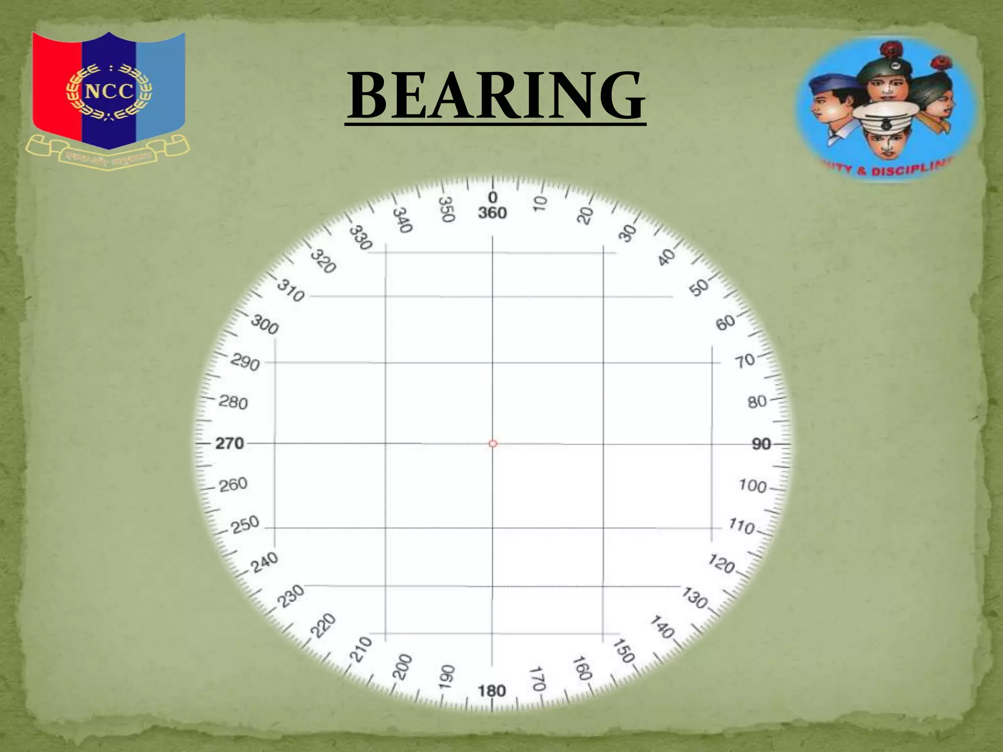
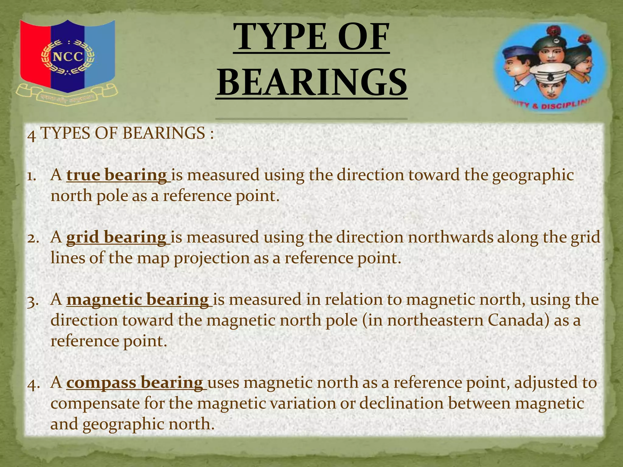
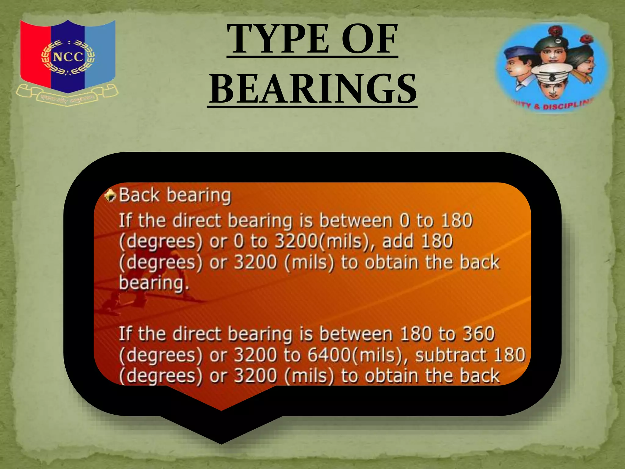
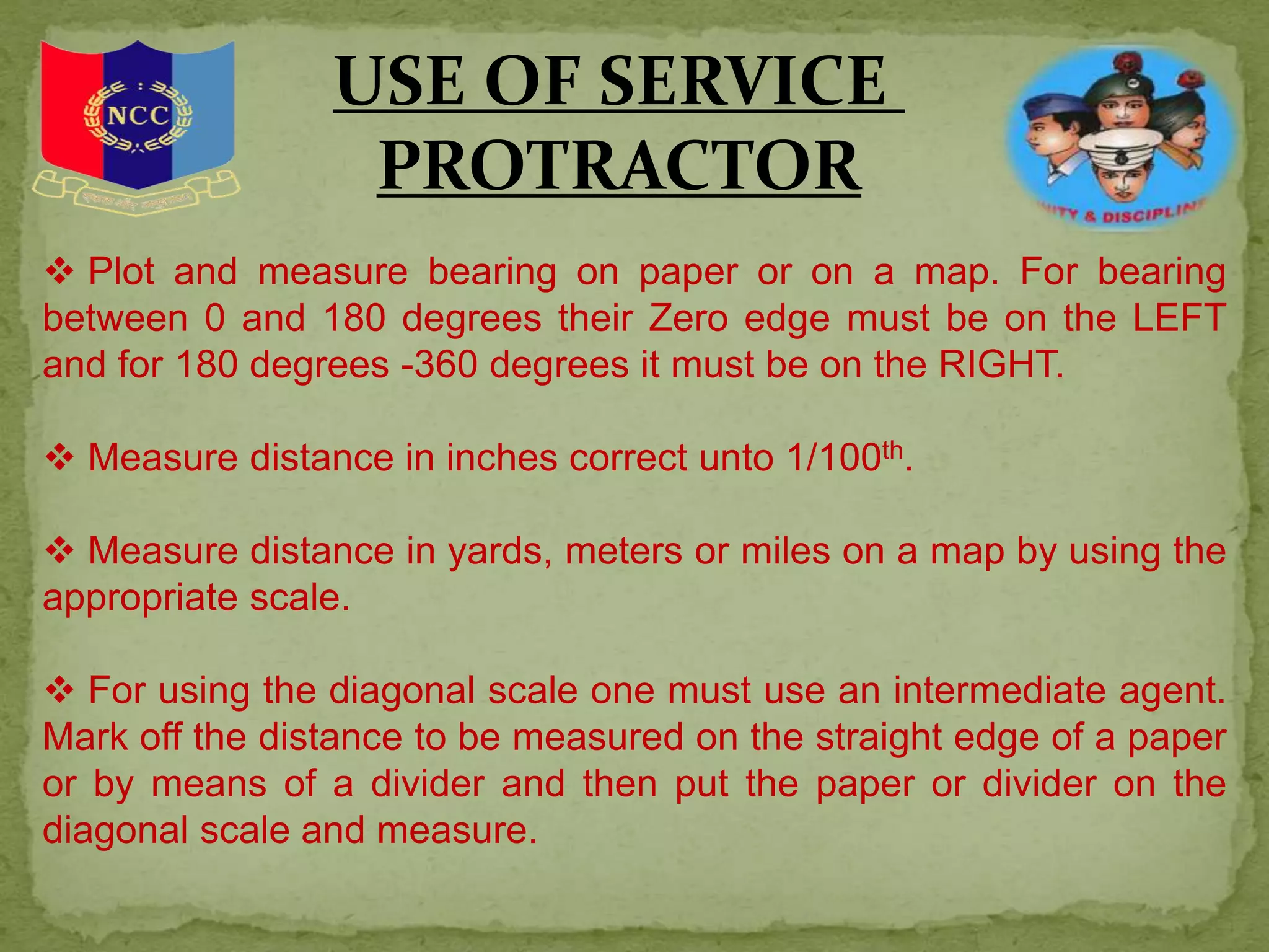
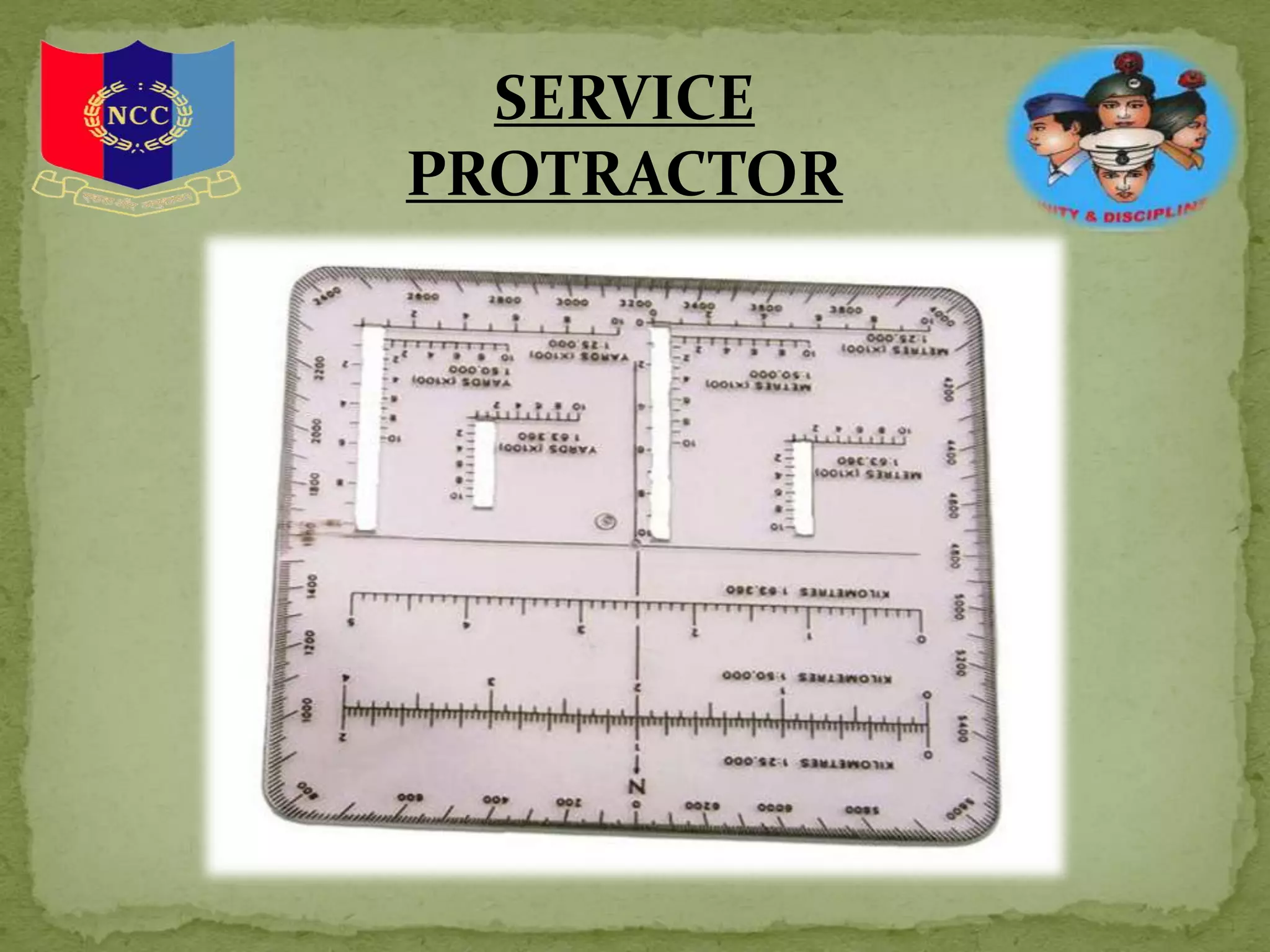
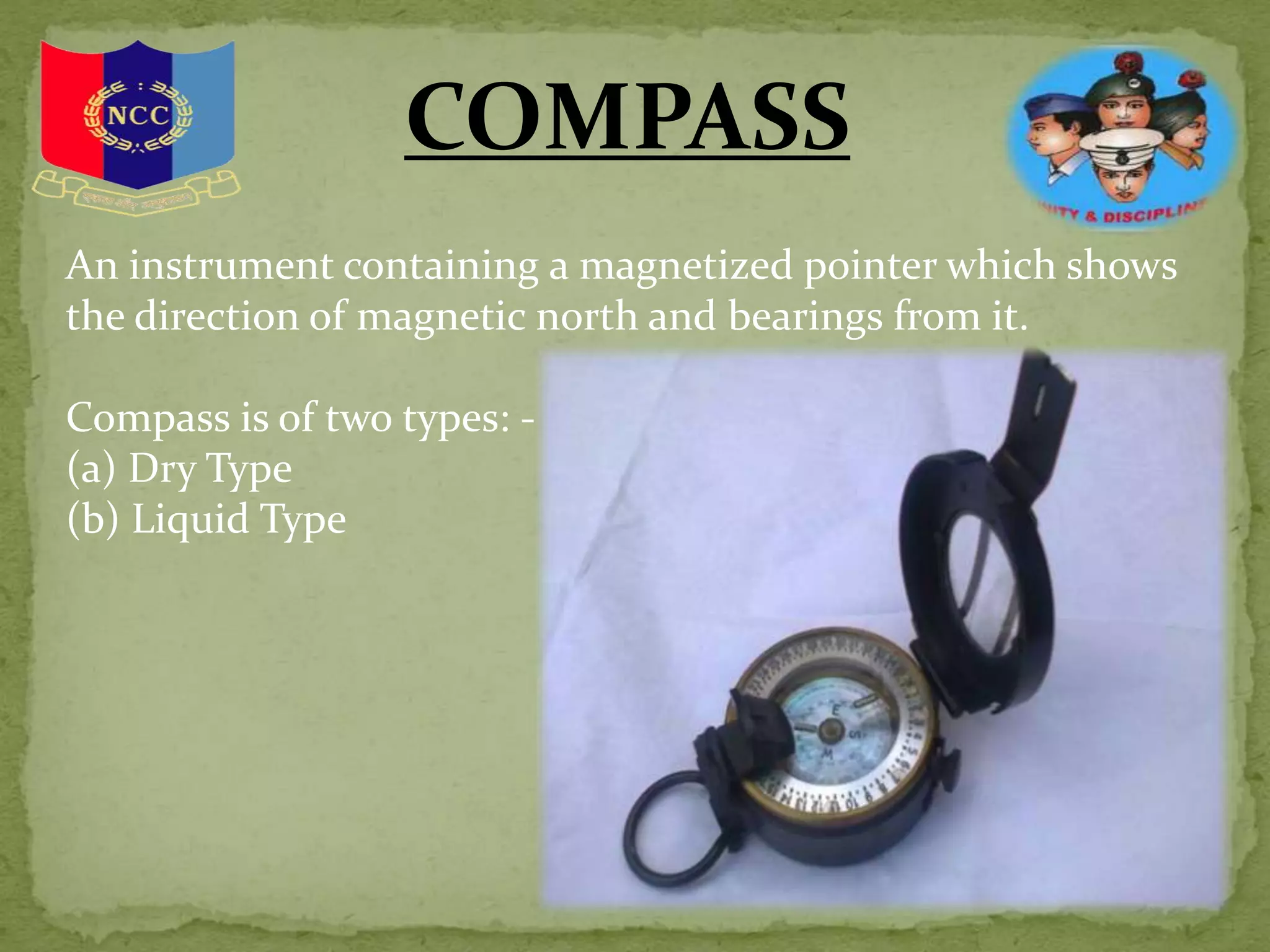
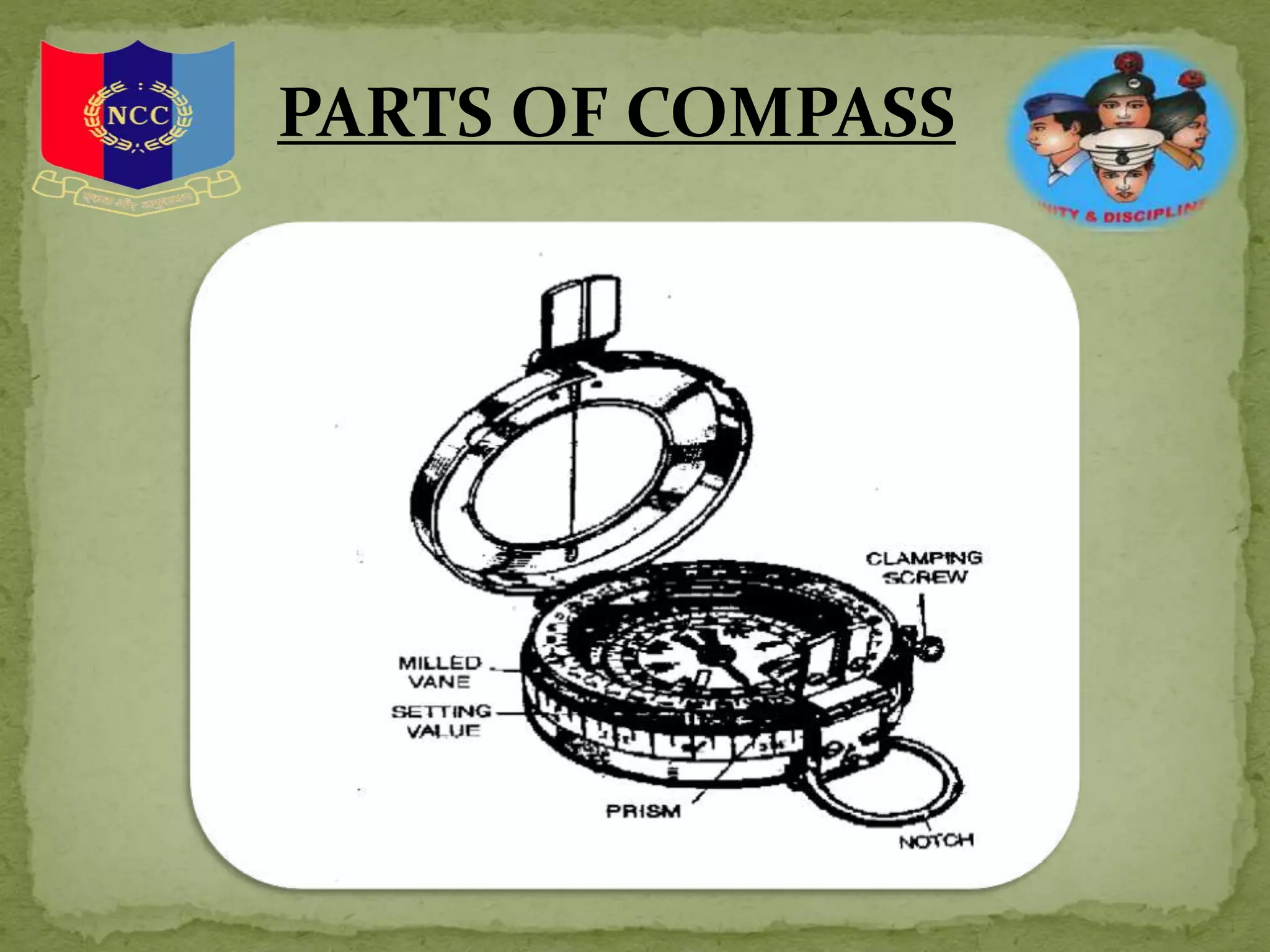
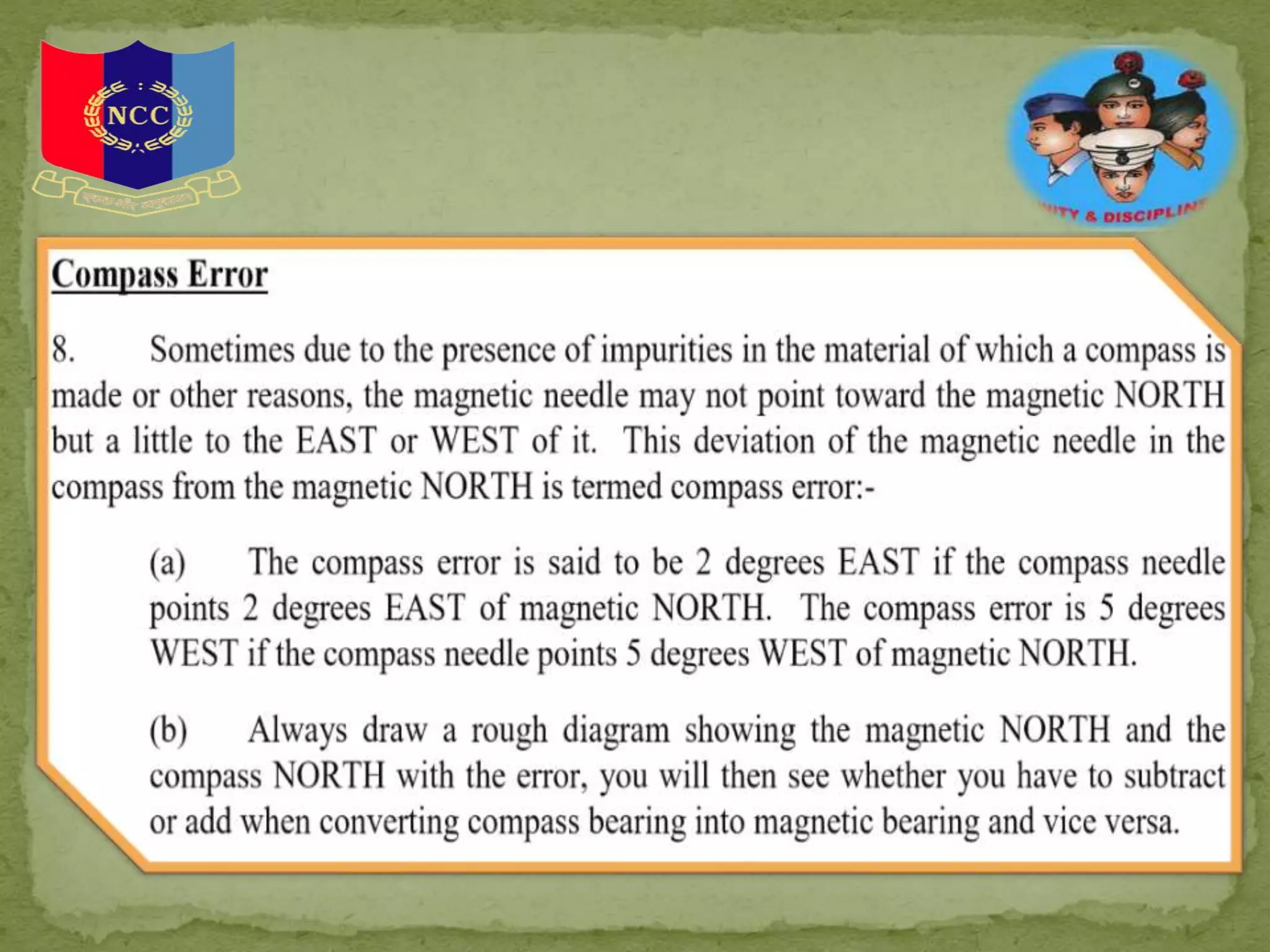
INTRO TO :
1. MAP AND CONVENTIONAL SIGNS
2. SOME TECHNICAL TERMS
3. GRID SYSTEM
4. COMPASS
5. SCALE
A map is representation of selected
natural and man made features of
the whole or part of the earth's
surface on a flat sheet of paper on a
definite scale and in their correct
relative geographic positions and
elevations.
CONVENTIONAL
SIGN
Conventional signs are
symbols used to
represent certain
artificial or natural
features/ objects on the
map. They are seldom
drawn to scale.
SCALE
The scale of a map is the ratio of a distance on the
map to the corresponding distance on the
ground.
The common scales used in survey of India maps
(a) 16 inches to 1 Mile 1/3960
(b) 4 inches to 1 mile 1/15840
(c) 2.53 inches to 1 mile 1/25000
(d) 1 inch to 1 mile 1/63360
(e) ½ inch to 1 mile 1/126720
(f) ¼ inch to 1 mile 1/253440
(g) 16 miles to 1 inch (Approx) 1/1000000
(h) 32 miles to 1 inch (Approx) 1/2000000
SCALE LINE
1 INCH = 50 FEETS
HOW TO MEASURE
DISTANCE
ON A MAP ?
 Straight line distance – Using ruler or a pair
of dividers
 Curved distance – Using ruler ( break the
curved distance into small
straight pieces)
A thread
OTHER METHODS INCLUDE :
1. Fkai Method
2. Dikhai method
3. Bracketing Method
4. Target indication
5. Direct method
6. Reference pt. method
7. Clock-Ray method
GRID SYSTEM
AND
MAP REFERENCES
Grid Lines - Lines running parallel to and at right angles to a
North and South line through approximately the centre of the
area covered by the grid system.
Grid North - Except through the origin, grid lines do not lie true
North and South or East and West, Grid North is the direction of
the North South grid lines on a map.
GRID SYSTEM
 A reference must always contain an even number of figures.
In the normal method, it will contain six figures.
 Always count along the EASTING lines first from WEST to
EAST and then from SOUTH to NORTH, along NORTHINGS.
 For the six figures reference, the third and the sixth figure
represent the divisions of 1000 yards square to the nearest 10th
part, so they have to be estimated and for these figures a slight
latitude is allow.
 If a general grid reference is to be given or there is only one
such object in one
square e.g. bridge, temple, road, junction, then a four figure grid
reference would suffice.
BASIC RUES FOR
GIVING GRID REFRENCE
GRATICULES
Graticules are lines showing parallels of latitude and meridians of longitude for
the earth.
These can be used to show location in geographic coordinates (degrees of
latitude and longitude). Below is a map of Europe where graticules are visible for
every 5 degrees latitude and 10 degrees longitude.
TOPOGRAPHICAL
FORMS AND
TECHNICAL TERMS
Bearing - The angle formed by a line joining two points and the North
and South line.
Bearings are always measured clockwise.
Bench Mark - A permanent mark usually cut into a wall recording exact
height for future reference, marked BM with the height on Ordnance Survey
Maps.
Contours - A line drawn on the map joining up all points of equal height
above sea level.
Gradient - The slope of a hill expressed as a fraction.
Grid Lines - Lines running parallel to and at right angles to a North and
South line through approximately the centre of the area covered by the grid
system.
Grid North - Except through the origin, grid lines do not lie
true North and South or East and West, Grid North is the
direction of the North South grid lines on a map.
Magnetic - The difference between true North & Magnetic
Variation North.
Setting - Placing a map so that North on the map points
toward the North so that the objects on the map are placed in
relationship to the same objects on the ground.
Trig Point - A point fixed during the triangulation at the
beginning of a survey, marked on Ordance Survey Maps by a
small triangle with the height.
True North - The direction of the North Pole from the point.
TOPOGRAPHICAL
FORMS AND
TECHNICAL TERMS
Basin - An area of fairly level ground surrounded by hills or the
area drained by a river and its distributaries.
Col or Saddle - A narrow ridge of high land joining up to higher
hills.
Crest – The highest part of a hill or mountain range. It is that line
on a range of hills or mountains from which the ground slopes down
in opposite directions.
Dead Ground - Ground which by reason of undulations or hills is
not visible to the observer.
Defile - Any feature whether natural or artificial which could cause
a body of troops to contract its front. An example of a natural defile is
mountain pass while a bridge is an example of an artificial defile.
TOPOGRAPHICAL
FORMS AND
TECHNICAL TERMS
TOPOGRAPHICAL
FORMS AND
TECHNICAL TERMS
Escarpment - The steep hill side formed by a sudden drop
in the general ground level usually from a plateau.
Knoll - A small isolated hill.
Plateau - A table land, an elevated region of considerable
extent generally fairly level.
Ridge - The line along a hill or range of hills or mountains
from which water flows in opposite directions, a divide,
sometimes and the crest of a line of hills as it appears along
the horizon.
Watershed - The line separating the water flowing into two
different river systems, the edge of a river basin.
RELIEF CONTOURS
AND GRADIENTS
Relief is a name used to describe the rise and fall of the ground or
in other words the hills and valleys.
Vertical Interval(VI) - The rise between successive contour lines is
known as the
vertical interval. On map scale 1 inch to 1 mile, the VI of each contour
line is 50 feet while on the ¼ inch to a mile it is 250 feet.
Horizontal Equivalent - The distance measured flat on the map
between adjacent contour lines is horizontal equivalent (HE).
Gradient - A gradient is a slope expressed as a fraction. If we say
that a slope has a gradient of 1 inch to 7 we mean for every 7 feet of
horizontal distance the slope rises or falls 1 foot vertically. Simple
Formula is VI/HE = Gradient. The horizontal equivalent is obtained
by measuring on the map and vertical interval by subtracting the
contour heights.
CARDINAL POINTS
AND FINDING
NORTH
True North - The direction
of North pole from the
observer.
Magnetic North- It is the
point to which an accurate
compass needle points, when
freely suspended.
Grid North - It is the
direction to which the North
South grid lines on a map
point.
BEARING
TYPE OF
BEARINGS
4 TYPES OF BEARINGS :
1. A true bearing is measured using the direction toward the geographic
north pole as a reference point.
2. A grid bearing is measured using the direction northwards along the grid
lines of the map projection as a reference point.
3. A magnetic bearing is measured in relation to magnetic north, using the
direction toward the magnetic north pole (in northeastern Canada) as a
reference point.
4. A compass bearing uses magnetic north as a reference point, adjusted to
compensate for the magnetic variation or declination between magnetic
and geographic north.
TYPE OF
BEARINGS
USE OF SERVICE
PROTRACTOR
 Plot and measure bearing on paper or on a map. For bearing
between 0 and 180 degrees their Zero edge must be on the LEFT
and for 180 degrees -360 degrees it must be on the RIGHT.
 Measure distance in inches correct unto 1/100th.
 Measure distance in yards, meters or miles on a map by using the
appropriate scale.
 For using the diagonal scale one must use an intermediate agent.
Mark off the distance to be measured on the straight edge of a paper
or by means of a divider and then put the paper or divider on the
diagonal scale and measure.
SERVICE
PROTRACTOR
COMPASS
An instrument containing a magnetized pointer which shows
the direction of magnetic north and bearings from it.
Compass is of two types: -
(a) Dry Type
(b) Liquid Type
PARTS OF COMPASS
PARTS OF COMPASS
HOW TO TAKE
BEARING
1. Open the lid of the compass.
2. Turn the prism casing over
3. Put your thumb through the ring.
4. Put the forefinger underneath the compass and
hold it to horizontal level.
5. Bring the prism up to eye.
6. See through the prism via hairline to object.
7. Read the bearing.
GPS is a system of satellites and receivers that allows people and
devices to pin point their precise location on the earth. The normal
GPS operational constellation consists of 24 satellites that orbit the
earth in 12 hours.
Usage of GPS
(a) Used by fishermen and hikers.
(b) Used by civilian & para military vehicles to navigate their route.
(c) Used by defense aircrafts, ships and specialized vehicles.
(d) Used in defense in battle fields and insurgency-affected areas.
(e) It assists troops to navigate in thick jungles, mountains and
deserts.
(f) GPS is also used to guide missiles to pre specified targets.
GPS
SETTING A MAP, FINDING OWN
POSITION AND NORTH
A map is said to be set or oriented when it is placed such that
it corresponds directly with the ground i.e. when true NORTH
on the map points to true NORTH on the ground.
Various methods to find North
(a) Watch method.
(b) By stars
(c) From Mosque
(d) From Sun
(e) Compass
(f) GPS
MAP TO GROUND
Methods used to identify objects from Map to ground
(a) Bearing and Distance Method. With the help of bearing and distance, find out
own position. Find out the distance of the object to be identified on ground with the
help of a scale on the map. Using service protractor, find out the bearing of the object
and convert it into magnetic bearing. Set the magnetic bearing on compass and look for
the object in the given bearing. Estimating the distance on ground, the object will be
identified.
(b) Direction and Distance Method. Draw a line on the map between own position
and object to be identified. Calculate its distance and using any of the following
methods find the direction of the object:-
(i) With the help of a sight rule find the ground direction of the object.
(ii) With the help of two points on the map estimate the ground direction.
(iii) Place a foot ruler /pencil at own position and align it with line of the ma
(iv) Place a pin each at own position and at the object on the map. Align both
pins and find general direction.
(c) By Estimation Method. In this method measuring bearing, distance and direction,
object is identified with the help of other details in the proximity of the object.
GROUND TO MAP
Intersection Method. To find out the objects which are at a larger
distance or in hilly terrain, intersection method is used. In this
method help of minimum two prominent objects are taken which
can be easily identified on the ground. Lines are drawn from the
prominent objects to the object to be identified on map. This
method is used when we cannot estimate exact distance.
Intersection is done in two ways:-
(a) By Compass Bearing. Take the bearing of the object from two
known prominent objects. Draw the lines on the map. The object
will be in the proximity of the intersection of the two lines. Magnetic
bearing is found by two methods:-
(i) By Compass. Take the forward bearing from known object.
(ii) By Back Bearing. In war, in case we intercept the enemy’s
transmission, with the help of the fall of the shot we can find out the
location by working out back bearing.
POINT TO POINT
MARCH
Presented by : NCC Cdt.PRANJAL SHARMA
MMDU,MULLANA

Map reading

  • 2.
    INTRO TO : 1.MAP AND CONVENTIONAL SIGNS 2. SOME TECHNICAL TERMS 3. GRID SYSTEM 4. COMPASS 5. SCALE
  • 3.
    A map isrepresentation of selected natural and man made features of the whole or part of the earth's surface on a flat sheet of paper on a definite scale and in their correct relative geographic positions and elevations.
  • 4.
    CONVENTIONAL SIGN Conventional signs are symbolsused to represent certain artificial or natural features/ objects on the map. They are seldom drawn to scale.
  • 5.
    SCALE The scale ofa map is the ratio of a distance on the map to the corresponding distance on the ground. The common scales used in survey of India maps (a) 16 inches to 1 Mile 1/3960 (b) 4 inches to 1 mile 1/15840 (c) 2.53 inches to 1 mile 1/25000 (d) 1 inch to 1 mile 1/63360 (e) ½ inch to 1 mile 1/126720 (f) ¼ inch to 1 mile 1/253440 (g) 16 miles to 1 inch (Approx) 1/1000000 (h) 32 miles to 1 inch (Approx) 1/2000000
  • 6.
  • 7.
    HOW TO MEASURE DISTANCE ONA MAP ?  Straight line distance – Using ruler or a pair of dividers  Curved distance – Using ruler ( break the curved distance into small straight pieces) A thread
  • 8.
    OTHER METHODS INCLUDE: 1. Fkai Method 2. Dikhai method 3. Bracketing Method 4. Target indication 5. Direct method 6. Reference pt. method 7. Clock-Ray method
  • 9.
    GRID SYSTEM AND MAP REFERENCES GridLines - Lines running parallel to and at right angles to a North and South line through approximately the centre of the area covered by the grid system. Grid North - Except through the origin, grid lines do not lie true North and South or East and West, Grid North is the direction of the North South grid lines on a map.
  • 10.
  • 12.
     A referencemust always contain an even number of figures. In the normal method, it will contain six figures.  Always count along the EASTING lines first from WEST to EAST and then from SOUTH to NORTH, along NORTHINGS.  For the six figures reference, the third and the sixth figure represent the divisions of 1000 yards square to the nearest 10th part, so they have to be estimated and for these figures a slight latitude is allow.  If a general grid reference is to be given or there is only one such object in one square e.g. bridge, temple, road, junction, then a four figure grid reference would suffice. BASIC RUES FOR GIVING GRID REFRENCE
  • 13.
    GRATICULES Graticules are linesshowing parallels of latitude and meridians of longitude for the earth. These can be used to show location in geographic coordinates (degrees of latitude and longitude). Below is a map of Europe where graticules are visible for every 5 degrees latitude and 10 degrees longitude.
  • 14.
    TOPOGRAPHICAL FORMS AND TECHNICAL TERMS Bearing- The angle formed by a line joining two points and the North and South line. Bearings are always measured clockwise. Bench Mark - A permanent mark usually cut into a wall recording exact height for future reference, marked BM with the height on Ordnance Survey Maps. Contours - A line drawn on the map joining up all points of equal height above sea level. Gradient - The slope of a hill expressed as a fraction. Grid Lines - Lines running parallel to and at right angles to a North and South line through approximately the centre of the area covered by the grid system.
  • 15.
    Grid North -Except through the origin, grid lines do not lie true North and South or East and West, Grid North is the direction of the North South grid lines on a map. Magnetic - The difference between true North & Magnetic Variation North. Setting - Placing a map so that North on the map points toward the North so that the objects on the map are placed in relationship to the same objects on the ground. Trig Point - A point fixed during the triangulation at the beginning of a survey, marked on Ordance Survey Maps by a small triangle with the height. True North - The direction of the North Pole from the point. TOPOGRAPHICAL FORMS AND TECHNICAL TERMS
  • 16.
    Basin - Anarea of fairly level ground surrounded by hills or the area drained by a river and its distributaries. Col or Saddle - A narrow ridge of high land joining up to higher hills. Crest – The highest part of a hill or mountain range. It is that line on a range of hills or mountains from which the ground slopes down in opposite directions. Dead Ground - Ground which by reason of undulations or hills is not visible to the observer. Defile - Any feature whether natural or artificial which could cause a body of troops to contract its front. An example of a natural defile is mountain pass while a bridge is an example of an artificial defile. TOPOGRAPHICAL FORMS AND TECHNICAL TERMS
  • 17.
    TOPOGRAPHICAL FORMS AND TECHNICAL TERMS Escarpment- The steep hill side formed by a sudden drop in the general ground level usually from a plateau. Knoll - A small isolated hill. Plateau - A table land, an elevated region of considerable extent generally fairly level. Ridge - The line along a hill or range of hills or mountains from which water flows in opposite directions, a divide, sometimes and the crest of a line of hills as it appears along the horizon. Watershed - The line separating the water flowing into two different river systems, the edge of a river basin.
  • 18.
    RELIEF CONTOURS AND GRADIENTS Reliefis a name used to describe the rise and fall of the ground or in other words the hills and valleys. Vertical Interval(VI) - The rise between successive contour lines is known as the vertical interval. On map scale 1 inch to 1 mile, the VI of each contour line is 50 feet while on the ¼ inch to a mile it is 250 feet. Horizontal Equivalent - The distance measured flat on the map between adjacent contour lines is horizontal equivalent (HE). Gradient - A gradient is a slope expressed as a fraction. If we say that a slope has a gradient of 1 inch to 7 we mean for every 7 feet of horizontal distance the slope rises or falls 1 foot vertically. Simple Formula is VI/HE = Gradient. The horizontal equivalent is obtained by measuring on the map and vertical interval by subtracting the contour heights.
  • 19.
    CARDINAL POINTS AND FINDING NORTH TrueNorth - The direction of North pole from the observer. Magnetic North- It is the point to which an accurate compass needle points, when freely suspended. Grid North - It is the direction to which the North South grid lines on a map point.
  • 22.
  • 23.
    TYPE OF BEARINGS 4 TYPESOF BEARINGS : 1. A true bearing is measured using the direction toward the geographic north pole as a reference point. 2. A grid bearing is measured using the direction northwards along the grid lines of the map projection as a reference point. 3. A magnetic bearing is measured in relation to magnetic north, using the direction toward the magnetic north pole (in northeastern Canada) as a reference point. 4. A compass bearing uses magnetic north as a reference point, adjusted to compensate for the magnetic variation or declination between magnetic and geographic north.
  • 24.
  • 25.
    USE OF SERVICE PROTRACTOR Plot and measure bearing on paper or on a map. For bearing between 0 and 180 degrees their Zero edge must be on the LEFT and for 180 degrees -360 degrees it must be on the RIGHT.  Measure distance in inches correct unto 1/100th.  Measure distance in yards, meters or miles on a map by using the appropriate scale.  For using the diagonal scale one must use an intermediate agent. Mark off the distance to be measured on the straight edge of a paper or by means of a divider and then put the paper or divider on the diagonal scale and measure.
  • 26.
  • 27.
    COMPASS An instrument containinga magnetized pointer which shows the direction of magnetic north and bearings from it. Compass is of two types: - (a) Dry Type (b) Liquid Type
  • 28.
  • 29.
  • 31.
    HOW TO TAKE BEARING 1.Open the lid of the compass. 2. Turn the prism casing over 3. Put your thumb through the ring. 4. Put the forefinger underneath the compass and hold it to horizontal level. 5. Bring the prism up to eye. 6. See through the prism via hairline to object. 7. Read the bearing.
  • 32.
    GPS is asystem of satellites and receivers that allows people and devices to pin point their precise location on the earth. The normal GPS operational constellation consists of 24 satellites that orbit the earth in 12 hours. Usage of GPS (a) Used by fishermen and hikers. (b) Used by civilian & para military vehicles to navigate their route. (c) Used by defense aircrafts, ships and specialized vehicles. (d) Used in defense in battle fields and insurgency-affected areas. (e) It assists troops to navigate in thick jungles, mountains and deserts. (f) GPS is also used to guide missiles to pre specified targets. GPS
  • 33.
    SETTING A MAP,FINDING OWN POSITION AND NORTH A map is said to be set or oriented when it is placed such that it corresponds directly with the ground i.e. when true NORTH on the map points to true NORTH on the ground. Various methods to find North (a) Watch method. (b) By stars (c) From Mosque (d) From Sun (e) Compass (f) GPS
  • 34.
    MAP TO GROUND Methodsused to identify objects from Map to ground (a) Bearing and Distance Method. With the help of bearing and distance, find out own position. Find out the distance of the object to be identified on ground with the help of a scale on the map. Using service protractor, find out the bearing of the object and convert it into magnetic bearing. Set the magnetic bearing on compass and look for the object in the given bearing. Estimating the distance on ground, the object will be identified. (b) Direction and Distance Method. Draw a line on the map between own position and object to be identified. Calculate its distance and using any of the following methods find the direction of the object:- (i) With the help of a sight rule find the ground direction of the object. (ii) With the help of two points on the map estimate the ground direction. (iii) Place a foot ruler /pencil at own position and align it with line of the ma (iv) Place a pin each at own position and at the object on the map. Align both pins and find general direction. (c) By Estimation Method. In this method measuring bearing, distance and direction, object is identified with the help of other details in the proximity of the object.
  • 35.
    GROUND TO MAP IntersectionMethod. To find out the objects which are at a larger distance or in hilly terrain, intersection method is used. In this method help of minimum two prominent objects are taken which can be easily identified on the ground. Lines are drawn from the prominent objects to the object to be identified on map. This method is used when we cannot estimate exact distance. Intersection is done in two ways:- (a) By Compass Bearing. Take the bearing of the object from two known prominent objects. Draw the lines on the map. The object will be in the proximity of the intersection of the two lines. Magnetic bearing is found by two methods:- (i) By Compass. Take the forward bearing from known object. (ii) By Back Bearing. In war, in case we intercept the enemy’s transmission, with the help of the fall of the shot we can find out the location by working out back bearing.
  • 36.
  • 42.
    Presented by :NCC Cdt.PRANJAL SHARMA MMDU,MULLANA